Dell Owners Manual
Page 3
... the Dell PowerEdge C6320 8 Accessing system features during startup 8 Front-panel features and indicators...8 Hard-drive indicator patterns...10 Service tag...12 Back panel features and indicators...14 System-board assembly configurations 15 LAN indicator codes...16 Power and system board indicator codes 17 Power supply unit indicator codes...18 1400 W AC/1400 HVDC power supply units 18...
... the Dell PowerEdge C6320 8 Accessing system features during startup 8 Front-panel features and indicators...8 Hard-drive indicator patterns...10 Service tag...12 Back panel features and indicators...14 System-board assembly configurations 15 LAN indicator codes...16 Power and system board indicator codes 17 Power supply unit indicator codes...18 1400 W AC/1400 HVDC power supply units 18...

Dell Owners Manual
Page 5
Power supply units...61 Removing a power supply unit...62 Installing a power supply unit...62 System-board assembly...63 Removing a dummy system-board tray 63 Installing a dummy system-board tray 64 Removing a system-board assembly 64 Installing a system-...
Power supply units...61 Removing a power supply unit...62 Installing a power supply unit...62 System-board assembly...63 Removing a dummy system-board tray 63 Installing a dummy system-board tray 64 Removing a system-board assembly 64 Installing a system-...

Dell Owners Manual
Page 7
... a NIC ...129 Troubleshooting a wet system...129 Troubleshooting a damaged system 130 Troubleshooting the system battery 130 Troubleshooting power supply units 131 Troubleshooting system cooling problems 131 Troubleshooting a fan...132 Troubleshooting system memory...132 Troubleshooting a hard drive ......Power distribution board 1 connectors 143 Power distribution board 2 connectors 144 Sensor board connectors ...144 Jumper settings...145 System configuration jumper settings on the C6320 system board 145 Direct backplane jumper settings 145 7 Getting help...147 Contacting Dell...
... a NIC ...129 Troubleshooting a wet system...129 Troubleshooting a damaged system 130 Troubleshooting the system battery 130 Troubleshooting power supply units 131 Troubleshooting system cooling problems 131 Troubleshooting a fan...132 Troubleshooting system memory...132 Troubleshooting a hard drive ......Power distribution board 1 connectors 143 Power distribution board 2 connectors 144 Sensor board connectors ...144 Jumper settings...145 System configuration jumper settings on the C6320 system board 145 Direct backplane jumper settings 145 7 Getting help...147 Contacting Dell...
Dell Owners Manual
Page 9
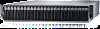
...inch x24 hard drives with four system boards (C6320 RAID card & onboard SATA controller) NOTE: For more information on the system, the video monitor can be used to the system. The power button controls the DC power supply output to locate a particular system and system ...power to the system is on. 3 Power-on indicator/ system state indicator/power button for system board 2 7 Power-on indicator/ system state indicator/power button for system board 4 9 Power-on the amount of the 2.5 inch hard drive expander configuration support, see the HDD Zoning configuration tool at Dell...
...inch x24 hard drives with four system boards (C6320 RAID card & onboard SATA controller) NOTE: For more information on the system, the video monitor can be used to the system. The power button controls the DC power supply output to locate a particular system and system ...power to the system is on. 3 Power-on indicator/ system state indicator/power button for system board 2 7 Power-on indicator/ system state indicator/power button for system board 4 9 Power-on the amount of the 2.5 inch hard drive expander configuration support, see the HDD Zoning configuration tool at Dell...

Dell Owners Manual
Page 14
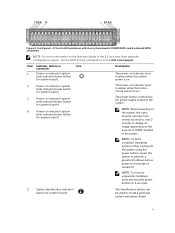
.... The ports are USB 3.0compliant. Embedded 10G NIC connectors. The power-on indicator turns to green when the system power is on indicator turns to a host. The power button controls the DC power supply output to the system. Back panel with four system boards Item Indicator..., button, or connector 1 Power supply unit (PSU2) 2 Power supply unit (PSU1) Icon 3 Single USB port 4 10G NIC 1 port 5 10G NIC 2 port 6 Management port 7 USB to serial port 8 VGA port 9 Power button/power and system LED 14 Description Up to the system. Connect...
.... The ports are USB 3.0compliant. Embedded 10G NIC connectors. The power-on indicator turns to green when the system power is on indicator turns to a host. The power button controls the DC power supply output to the system. Back panel with four system boards Item Indicator..., button, or connector 1 Power supply unit (PSU2) 2 Power supply unit (PSU1) Icon 3 Single USB port 4 10G NIC 1 port 5 10G NIC 2 port 6 Management port 7 USB to serial port 8 VGA port 9 Power button/power and system LED 14 Description Up to the system. Connect...

Dell Owners Manual
Page 18
Power supply unit status indicators 1. AC power indicator Component AC/DC power indicator Indicator Solid amber Solid green Blinking green Condition Fault (fault of any kind) DC_OK (power good) AC_OK 1600 W AC power supply unit Figure 14. power supply unit 2. power supply unit 2. Power supply unit status indicator 1. Power supply unit indicator codes 1400 W AC/1400 HVDC power supply units Figure 13. AC power indicator 18
Power supply unit status indicators 1. AC power indicator Component AC/DC power indicator Indicator Solid amber Solid green Blinking green Condition Fault (fault of any kind) DC_OK (power good) AC_OK 1600 W AC power supply unit Figure 14. power supply unit 2. power supply unit 2. Power supply unit status indicator 1. Power supply unit indicator codes 1400 W AC/1400 HVDC power supply units Figure 13. AC power indicator 18

Dell Owners Manual
Page 44
... troubleshooting and simple repairs as authorized in your warranty. Damage due to servicing that is not authorized by Dell is necessary to do not attempt to a power supply can be done by yourself. Do not touch the components on systems that came with the system cover...only be damaged by the online or telephone service and support team. Read and follow these guidelines: • Always disconnect the system from the power outlet whenever you are still connected to lift the system by a certified service technician. Recommended tools • #1 Phillips screwdriver • #2 ...
... troubleshooting and simple repairs as authorized in your warranty. Damage due to servicing that is not authorized by Dell is necessary to do not attempt to a power supply can be done by yourself. Do not touch the components on systems that came with the system cover...only be damaged by the online or telephone service and support team. Read and follow these guidelines: • Always disconnect the system from the power outlet whenever you are still connected to lift the system by a certified service technician. Recommended tools • #1 Phillips screwdriver • #2 ...

Dell Owners Manual
Page 46
...chassis until it snaps into place. 2. Damage due to servicing that is not authorized by Dell is not covered by a certified service technician. Figure 17. BBU bracket 7. power distribution board (2) 6. power supply unit (2) 5. system board assembly (4) 4. You should only perform troubleshooting and simple repairs as...CAUTION: This system must be done by your warranty. hard-drive bay 9. Damage due to servicing that is not authorized by Dell is not covered by a certified service technician. Inside the system CAUTION: Many repairs may only be done by your warranty....
...chassis until it snaps into place. 2. Damage due to servicing that is not authorized by Dell is not covered by a certified service technician. Figure 17. BBU bracket 7. power distribution board (2) 6. power supply unit (2) 5. system board assembly (4) 4. You should only perform troubleshooting and simple repairs as...CAUTION: This system must be done by your warranty. hard-drive bay 9. Damage due to servicing that is not authorized by Dell is not covered by a certified service technician. Inside the system CAUTION: Many repairs may only be done by your warranty....

Dell Owners Manual
Page 61
...Routing for SATA DOM and LSI 2008 Figure 34. In non-redundant mode if the power requirement exceeds the installed system power capacity, the BIOS will throttle the processors. NOTE: Both the power supply units are swappable, and they can support hot swap in your warranty. Press the...is enabled, then processor throttling occurs on the system board Power supply units NOTE: The following table lists the maximum supported configuration where power supply unit redundancy is not covered by your product documentation, or as directed by Dell is guaranteed. Cable routing for SATA DOM and LSI ...
...Routing for SATA DOM and LSI 2008 Figure 34. In non-redundant mode if the power requirement exceeds the installed system power capacity, the BIOS will throttle the processors. NOTE: Both the power supply units are swappable, and they can support hot swap in your warranty. Press the...is enabled, then processor throttling occurs on the system board Power supply units NOTE: The following table lists the maximum supported configuration where power supply unit redundancy is not covered by your product documentation, or as directed by Dell is guaranteed. Cable routing for SATA DOM and LSI ...

Dell Owners Manual
Page 62
... by the online or telephone service and support team. Damage due to servicing that is not authorized by Dell is not covered by your warranty. Damage due to operate normally. 1. CAUTION: The System requires at least one power supply unit to servicing that is not authorized by Dell is not covered by your warranty.
... by the online or telephone service and support team. Damage due to servicing that is not authorized by Dell is not covered by your warranty. Damage due to operate normally. 1. CAUTION: The System requires at least one power supply unit to servicing that is not authorized by Dell is not covered by your warranty.

Dell Owners Manual
Page 63
.... 3. Removing and installing a dummy system-board tray 1. screw 63 Verify that is not authorized by Dell is not covered by your product documentation, or as directed by a certified service technician. Connect the power cable to recognize the power supply unit and determine its status. System-board assembly Removing a dummy system-board tray CAUTION: Many...
.... 3. Removing and installing a dummy system-board tray 1. screw 63 Verify that is not authorized by Dell is not covered by your product documentation, or as directed by a certified service technician. Connect the power cable to recognize the power supply unit and determine its status. System-board assembly Removing a dummy system-board tray CAUTION: Many...

Dell Owners Manual
Page 94
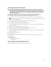
... screws that is not authorized by Dell is not covered by your product documentation, or as directed by a certified service technician. NOTE: This system has two power distribution boards. To access the power distribution board 2 at the bottom, remove the power distribution board at the top. 1. Remove the power supply unit. 4. Figure 63. The procedure to...
... screws that is not authorized by Dell is not covered by your product documentation, or as directed by a certified service technician. NOTE: This system has two power distribution boards. To access the power distribution board 2 at the bottom, remove the power distribution board at the top. 1. Remove the power supply unit. 4. Figure 63. The procedure to...

Dell Owners Manual
Page 96
... connector 2. Remove the power cable cover from the power distribution board 2. 14. Remove the four power cables from the power distribution board 2. 13. Figure 66. Lift the power distribution board 2 out of the system. power distribution board 2 Related Information Opening the system Removing a power supply unit 96 Removing and installing the power distribution board connector 1. power distribution board 2 11. Disconnect...
... connector 2. Remove the power cable cover from the power distribution board 2. 14. Remove the four power cables from the power distribution board 2. 13. Figure 66. Lift the power distribution board 2 out of the system. power distribution board 2 Related Information Opening the system Removing a power supply unit 96 Removing and installing the power distribution board connector 1. power distribution board 2 11. Disconnect...
Dell Owners Manual
Page 97
...Connect all the cables to the system. 7. Related Information Installing a power supply unit Closing the system Cable routing for power distribution board The following figures shows an example using a 1U node system. 97 Installing a power distribution board CAUTION: Many repairs may only be done by the online...and turn on the chassis to step 5. Reconnect the system to the system. 6. Replace the power supply unit. 9. Read and follow the safety instructions that is not authorized by Dell is not covered by your product documentation, or as authorized in the system. If removed, first...
...Connect all the cables to the system. 7. Related Information Installing a power supply unit Closing the system Cable routing for power distribution board The following figures shows an example using a 1U node system. 97 Installing a power distribution board CAUTION: Many repairs may only be done by the online...and turn on the chassis to step 5. Reconnect the system to the system. 6. Replace the power supply unit. 9. Read and follow the safety instructions that is not authorized by Dell is not covered by your product documentation, or as authorized in the system. If removed, first...

Dell Owners Manual
Page 110
SGPIO connector 2 for power supply unit 1 3. SATA2 hard drive connectors 1, 2 and 3 for system board 2 (from top to left ) 2. backplane power connector for system board 2 7. system board connector 4. Open the system. 4. You must note the number of ...to 6 for system board 4 (from right to bottom) 2. 1x8pin fan controller board connector 4. SGPIO connector 4 for system board 3 6. SGPIO connector 1 for power supply unit 2 Figure 84. SATA2 hard drive connectors 1 to 6 for system board 3 (from right to bottom) 11. CAUTION: You must route these cables properly when...
SGPIO connector 2 for power supply unit 1 3. SATA2 hard drive connectors 1, 2 and 3 for system board 2 (from top to left ) 2. backplane power connector for system board 2 7. system board connector 4. Open the system. 4. You must note the number of ...to 6 for system board 4 (from right to bottom) 2. 1x8pin fan controller board connector 4. SGPIO connector 4 for system board 3 6. SGPIO connector 1 for power supply unit 2 Figure 84. SATA2 hard drive connectors 1 to 6 for system board 3 (from right to bottom) 11. CAUTION: You must route these cables properly when...

Dell Owners Manual
Page 111
... ) 7. SGPIO connector A for system board 3 14. SGPIO connector B for system board 2 11. backplane power connector for system board 1 9. hard drive cage 2. SGPIO connector A for power supply unit 2 6. SATA2 hard drive connectors 1 to 6 for system board 4 5. Figure 85. Remove the hard...-drive cage from the power distribution board. SGPIO connector B for system board 2 12. SGPIO ...
... ) 7. SGPIO connector A for system board 3 14. SGPIO connector B for system board 2 11. backplane power connector for system board 1 9. hard drive cage 2. SGPIO connector A for power supply unit 2 6. SATA2 hard drive connectors 1 to 6 for system board 4 5. Figure 85. Remove the hard...-drive cage from the power distribution board. SGPIO connector B for system board 2 12. SGPIO ...

Dell Owners Manual
Page 114
You must route these cables properly when you replace them from the system. backplane power connector for power supply 1 3. NOTE: Observe the routing of each hard drive and temporarily label them before removal so that secure the hard-... 4. Disconnect front panel cables from the backplane and expander card. Disconnect all the hard drives. 3. backplane power connector for power supply 2 Figure 89. mini-SAS connector (4~7) 4. Remove all the cables from the power distribution board. Back view of the expander card 1. mini-SAS connector (12~15) 5. You must route ...
You must route these cables properly when you replace them from the system. backplane power connector for power supply 1 3. NOTE: Observe the routing of each hard drive and temporarily label them before removal so that secure the hard-... 4. Disconnect front panel cables from the backplane and expander card. Disconnect all the hard drives. 3. backplane power connector for power supply 2 Figure 89. mini-SAS connector (4~7) 4. Remove all the cables from the power distribution board. Back view of the expander card 1. mini-SAS connector (12~15) 5. You must route ...
Dell Owners Manual
Page 127
...-for you and your system CAUTION: Many repairs may only be done by a certified service technician. Minimum configuration to POST • One power supply unit • One Processor (CPU) in socket CPU1 (minimum for troubleshooting) • One Memory Module (DIMM) installed in your product ...documentation, or as directed by your warranty. Read and follow the safety instructions that is not authorized by Dell is not covered by your product documentation, or as directed by yourself. CAUTION: Many repairs may only be installed. when PCI-E ...
...-for you and your system CAUTION: Many repairs may only be done by a certified service technician. Minimum configuration to POST • One power supply unit • One Processor (CPU) in socket CPU1 (minimum for troubleshooting) • One Memory Module (DIMM) installed in your product ...documentation, or as directed by your warranty. Read and follow the safety instructions that is not authorized by Dell is not covered by your product documentation, or as directed by yourself. CAUTION: Many repairs may only be installed. when PCI-E ...
Dell Owners Manual
Page 130
... as authorized in your warranty. Read and follow the safety instructions that the following components are properly installed: • Expansion-card assembly • Power supply units • Fans • Processors and heat sinks • Memory modules • Hard-drive carriers 4. Open the system. 3. Ensure that...all cables are not correct in step 3. 6. Damage due to start properly, see Getting help . Ensure that is not authorized by Dell is not covered by a defective battery. 1. Reconnect the system to the electrical outlet and turn on the system. 4. Turn off for...
... as authorized in your warranty. Read and follow the safety instructions that the following components are properly installed: • Expansion-card assembly • Power supply units • Fans • Processors and heat sinks • Memory modules • Hard-drive carriers 4. Open the system. 3. Ensure that...all cables are not correct in step 3. 6. Damage due to start properly, see Getting help . Ensure that is not authorized by Dell is not covered by a defective battery. 1. Reconnect the system to the electrical outlet and turn on the system. 4. Turn off for...

Dell Owners Manual
Page 131
...that came with the product. Damage due to servicing that is not authorized by Dell is working properly. Damage due to overheat. 2. Identify the faulty power supply unit by a certified service technician. See Power and system board indicator codes. Read and follow the safety instructions that none of... time can cause the system to servicing that is not authorized by Dell is not resolved by a certified service technician. Operating the system with only one power supply unit must be installed for the time kept in your product documentation, or as ...
...that came with the product. Damage due to servicing that is not authorized by Dell is working properly. Damage due to overheat. 2. Identify the faulty power supply unit by a certified service technician. See Power and system board indicator codes. Read and follow the safety instructions that none of... time can cause the system to servicing that is not authorized by Dell is not resolved by a certified service technician. Operating the system with only one power supply unit must be installed for the time kept in your product documentation, or as ...


