
Glossary
Page 1
...quick data retrieval. A copy of the area or room where the system is used to direct configuration and power management. The modules are mounted into a chassis that contains a processor, memory, and a hard drive. A CD, diskette, or USB memory key that keeps a copy of a system. bus -...up your system if the system will not boot from SNMP agents. bootable media - An information pathway between the processor and RAM. Dell™ Glossary NOTE: For additional information on storage terminology, visit the Storage Networking Industry Association's website at www.snia.org and click...
...quick data retrieval. A copy of the area or room where the system is used to direct configuration and power management. The modules are mounted into a chassis that contains a processor, memory, and a hard drive. A CD, diskette, or USB memory key that keeps a copy of a system. bus -...up your system if the system will not boot from SNMP agents. bootable media - An information pathway between the processor and RAM. Dell™ Glossary NOTE: For additional information on storage terminology, visit the Storage Networking Industry Association's website at www.snia.org and click...

User Manual
Page 7
NOTE: To remove the rails, pull on the latch release button on the end piece midpoint and unseat each rail. 5 Tighten the thumbscrews to secure the ears of system to the front of the rack. Getting Started With Your System | 5 4 If present, remove the chassis stabilizer shipping bracket (optional) from the rack.
NOTE: To remove the rails, pull on the latch release button on the end piece midpoint and unseat each rail. 5 Tighten the thumbscrews to secure the ears of system to the front of the rack. Getting Started With Your System | 5 4 If present, remove the chassis stabilizer shipping bracket (optional) from the rack.

Hardware Owner's Manual
Page 14
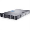
... 2,4,6,8 System identification indicator/button (system boards 1,2,4,3) 5 Hard Drives * Drive Cover Description The identification button can be used to locate a particular system and system board within a chassis. Hard-Drive Indicator Patterns Figure 1-5.
... 2,4,6,8 System identification indicator/button (system boards 1,2,4,3) 5 Hard Drives * Drive Cover Description The identification button can be used to locate a particular system and system board within a chassis. Hard-Drive Indicator Patterns Figure 1-5.

Hardware Owner's Manual
Page 22
... in Power Off mode S5 BMC Critical condition event in Power On mode S0/S1 IPMI Via OEM Command On IPMI using Chassis Identify Command Blink On or ID Button Press ID On IPMI using Chassis Identify Command Off or ID Button Press ID Off Power Supply Indicator Codes Figure 1-11. Table 1-2.
... in Power Off mode S5 BMC Critical condition event in Power On mode S0/S1 IPMI Via OEM Command On IPMI using Chassis Identify Command Blink On or ID Button Press ID On IPMI using Chassis Identify Command Off or ID Button Press ID Off Power Supply Indicator Codes Figure 1-11. Table 1-2.

Hardware Owner's Manual
Page 37
The setting controls PSU Power, its range limited in the chassis. This setting only can decide the highest performance P-state in OS. Option Power Management (OS Control default) CPU Power Capping (P-state 0 default) PSU Power Capping (...
The setting controls PSU Power, its range limited in the chassis. This setting only can decide the highest performance P-state in OS. Option Power Management (OS Control default) CPU Power Capping (P-state 0 default) PSU Power Capping (...

Hardware Owner's Manual
Page 58
...system. Recommended Tools • Phillips screwdriver • Flat-tipped screwdriver • Set of any static electricity by touching the bare metal chassis of the system case, or the bare metal body of jewelers screwdrivers 58 | Installing System Components CAUTION: Many repairs may only be...still connected to a power supply can be damaged by discharge of static electricity. Damage due to servicing that is not authorized by Dell is necessary to use the component for the installation. Alternatively, discharge any other grounded appliance. • Hold electronic circuit boards by ...
...system. Recommended Tools • Phillips screwdriver • Flat-tipped screwdriver • Set of any static electricity by touching the bare metal chassis of the system case, or the bare metal body of jewelers screwdrivers 58 | Installing System Components CAUTION: Many repairs may only be...still connected to a power supply can be damaged by discharge of static electricity. Damage due to servicing that is not authorized by Dell is necessary to use the component for the installation. Alternatively, discharge any other grounded appliance. • Hold electronic circuit boards by ...

Hardware Owner's Manual
Page 67
... the product. NOTE: The maximum output power is printed on the power supply label. 2 Slide the new power supply into the chassis until the power supply is not covered by Dell is fully seated and the release lever snaps into a Installing System Components | 67 Read and follow the safety instructions that both...
... the product. NOTE: The maximum output power is printed on the power supply label. 2 Slide the new power supply into the chassis until the power supply is not covered by Dell is fully seated and the release lever snaps into a Installing System Components | 67 Read and follow the safety instructions that both...

Hardware Owner's Manual
Page 68
See Figure 3-6. 4 Press the retaining latch and using the handle, slide the system-board assembly out of the chassis. System-Board Assembly Removing a System-Board Assembly CAUTION: Many repairs may only be done by the online or telephone service and support team. See ...the power supply and determine its electrical outlet. 2 Disconnect all the external cables from the system board. 3 Remove the screw that is not authorized by Dell is not covered by your product documentation, or as authorized in a system with the product. 1 Turn off the system, including any attached peripherals, ...
See Figure 3-6. 4 Press the retaining latch and using the handle, slide the system-board assembly out of the chassis. System-Board Assembly Removing a System-Board Assembly CAUTION: Many repairs may only be done by the online or telephone service and support team. See ...the power supply and determine its electrical outlet. 2 Disconnect all the external cables from the system board. 3 Remove the screw that is not authorized by Dell is not covered by your product documentation, or as authorized in a system with the product. 1 Turn off the system, including any attached peripherals, ...

Hardware Owner's Manual
Page 69
...secures the retaining latch. See Figure 3-6. 4 Reconnect the system to the system board. 3 Replace the screw that is not authorized by Dell is not covered by your product documentation, or as directed by a certified service technician. Installing System Components | 69 See Figure 3-6. 2 ... any attached peripherals. Read and follow the safety instructions that came with the product. 1 Slide the system-board assembly into the chassis until it snaps into place. Figure 3-6. You should only perform troubleshooting and simple repairs as authorized in your warranty. Removing and ...
...secures the retaining latch. See Figure 3-6. 4 Reconnect the system to the system board. 3 Replace the screw that is not authorized by Dell is not covered by your product documentation, or as directed by a certified service technician. Installing System Components | 69 See Figure 3-6. 2 ... any attached peripherals. Read and follow the safety instructions that came with the product. 1 Slide the system-board assembly into the chassis until it snaps into place. Figure 3-6. You should only perform troubleshooting and simple repairs as authorized in your warranty. Removing and ...

Hardware Owner's Manual
Page 98
Cooling Fans Removing a Cooling Fan WARNING: Do not attempt to spin for the fan to the front of the chassis until it from the system. 98 | Installing System Components WARNING: The cooling fan can continue to operate the system without the cooling fans. See Figure 3-... Figure 3-20. Opening and Closing the System 1 traction pad 3 cover release latch lock 2 system cover 4 securing screw Closing the System 1 Place the cover on the chassis and slide it to stop spinning before removing it snaps into place. Figure 3-20. Allow time for some time after the system has been powered...
Cooling Fans Removing a Cooling Fan WARNING: Do not attempt to spin for the fan to the front of the chassis until it from the system. 98 | Installing System Components WARNING: The cooling fan can continue to operate the system without the cooling fans. See Figure 3-... Figure 3-20. Opening and Closing the System 1 traction pad 3 cover release latch lock 2 system cover 4 securing screw Closing the System 1 Place the cover on the chassis and slide it to stop spinning before removing it snaps into place. Figure 3-20. Allow time for some time after the system has been powered...

Hardware Owner's Manual
Page 99
Damage due to prevent the cables from its electrical outlet. 2 Open the system. See "Opening the System" on the chassis as directed by the online or telephone service and support team. Figure 3-21. Removing and Installing a Cooling Fan 1 cooling-fan cage 2 cooling fans (4) ...by your product documentation, or as you replace them from the fan-controller board. Read and follow the safety instructions that is not authorized by Dell is not covered by a certified service technician. Note the routing of the cooling-fan cage. You must route these cables properly when you remove...
Damage due to prevent the cables from its electrical outlet. 2 Open the system. See "Opening the System" on the chassis as directed by the online or telephone service and support team. Figure 3-21. Removing and Installing a Cooling Fan 1 cooling-fan cage 2 cooling fans (4) ...by your product documentation, or as you replace them from the fan-controller board. Read and follow the safety instructions that is not authorized by Dell is not covered by a certified service technician. Note the routing of the cooling-fan cage. You must route these cables properly when you remove...

Hardware Owner's Manual
Page 100
...service technician. Damage due to the connector on the system, including any attached peripherals. You must route these cables properly through the tabs on the chassis to its electrical outlet and turn on the fan-controller board. You should face the front panel of the system. 2 Connect the fan's ...power cable to servicing that is not authorized by Dell is not covered by the online or telephone service and support team. Damage due to remove and install both the power distribution boards is firmly...
...service technician. Damage due to the connector on the system, including any attached peripherals. You must route these cables properly through the tabs on the chassis to its electrical outlet and turn on the fan-controller board. You should face the front panel of the system. 2 Connect the fan's ...power cable to servicing that is not authorized by Dell is not covered by the online or telephone service and support team. Damage due to remove and install both the power distribution boards is firmly...

Hardware Owner's Manual
Page 101
... board connector and angle the board before lifting. See Figure 3-22. 6 Lift the power distribution board out of the cable underneath the tabs on the chassis as you replace them from the first power distribution board. 1 Turn off the system, including any attached peripherals, and disconnect the system from being pinched...
... board connector and angle the board before lifting. See Figure 3-22. 6 Lift the power distribution board out of the cable underneath the tabs on the chassis as you replace them from the first power distribution board. 1 Turn off the system, including any attached peripherals, and disconnect the system from being pinched...

Hardware Owner's Manual
Page 103
... prevent them from being pinched or crimped. 7 Replace the power supply. See "Installing a Power Supply" on the chassis to servicing that came with the product. Damage due to prevent them from being pinched or crimped. 5 Replace the screws securing the first... | 103 See "Closing the System" on the system, including any attached peripherals. Read and follow the safety instructions that is not authorized by Dell is below the first power distribution board, angle the board during installation. 2 Replace the screws securing the second power distribution board to the first ...
... prevent them from being pinched or crimped. 7 Replace the power supply. See "Installing a Power Supply" on the chassis to servicing that came with the product. Damage due to prevent them from being pinched or crimped. 5 Replace the screws securing the first... | 103 See "Closing the System" on the system, including any attached peripherals. Read and follow the safety instructions that is not authorized by Dell is below the first power distribution board, angle the board during installation. 2 Replace the screws securing the second power distribution board to the first ...

Hardware Owner's Manual
Page 104
...system. Figure 3-23. 1 Turn off the system, including any attached peripherals, and disconnect the system from the fan controller board. Note the routing of the chassis. See Figure 3-23. 6 Slide and lift the fan controller board out of the cable underneath the tabs on the... chassis as you replace them from being pinched or crimped. 5 Remove the screw securing the fan controller board to the chassis. See Figure 5-11. Removing and Installing the Fan Controller Board 1 fan controller board 2 screw...
...system. Figure 3-23. 1 Turn off the system, including any attached peripherals, and disconnect the system from the fan controller board. Note the routing of the chassis. See Figure 3-23. 6 Slide and lift the fan controller board out of the cable underneath the tabs on the... chassis as you replace them from being pinched or crimped. 5 Remove the screw securing the fan controller board to the chassis. See Figure 5-11. Removing and Installing the Fan Controller Board 1 fan controller board 2 screw...

Hardware Owner's Manual
Page 105
...properly through the tabs on page 102. 5 Close the system. See "Installing a Power Distribution Board" on the chassis to servicing that is not authorized by Dell is not covered by a certified service technician. Installing System Components | 105 Middle Planes Removing the Middle Planes CAUTION...the product. 1 Turn off the system, including any attached peripherals. See Figure 3-23. 3 Connect all the cables to the chassis. You should only perform troubleshooting and simple repairs as authorized in your product documentation, or as directed by the online or telephone ...
...properly through the tabs on page 102. 5 Close the system. See "Installing a Power Distribution Board" on the chassis to servicing that is not authorized by Dell is not covered by a certified service technician. Installing System Components | 105 Middle Planes Removing the Middle Planes CAUTION...the product. 1 Turn off the system, including any attached peripherals. See Figure 3-23. 3 Connect all the cables to the chassis. You should only perform troubleshooting and simple repairs as authorized in your product documentation, or as directed by the online or telephone ...

Hardware Owner's Manual
Page 106
...the cooling-fan brackets out of the cable underneath the tabs on page 98. 5 Remove the screws that secure the upper middle plane to the chassis. Removing and Installing the Cooling-Fan Brackets 1 cooling fan bracket (long) 3 cooling fan bracket (short) 2 Screw (14) 7 Remove the...the middle plane holder. Figure 3-25. 8 Disconnect all the cables from being pinched or crimped. 106 | Installing System Components Note the routing of the chassis. See "Removing a System-Board Assembly" on page 97. 3 Remove the system-board assemblies. See Figure 3-24. 2 Open the system. See "...
...the cooling-fan brackets out of the cable underneath the tabs on page 98. 5 Remove the screws that secure the upper middle plane to the chassis. Removing and Installing the Cooling-Fan Brackets 1 cooling fan bracket (long) 3 cooling fan bracket (short) 2 Screw (14) 7 Remove the...the middle plane holder. Figure 3-25. 8 Disconnect all the cables from being pinched or crimped. 106 | Installing System Components Note the routing of the chassis. See "Removing a System-Board Assembly" on page 97. 3 Remove the system-board assemblies. See Figure 3-24. 2 Open the system. See "...

Hardware Owner's Manual
Page 107
See Figure 3-26. 11 Lift the mid-plane holder support out of the chassis. 9 Lift the upper middle plane out. Figure 3-26. Removing and Installing the Upper Middle Plane 1 screw (9) 2 upper middle plane 10 Remove the screws that secure the mid-plane holder support to the chassis. Installing System Components | 107 See Figure 3-25. Figure 3-25.
See Figure 3-26. 11 Lift the mid-plane holder support out of the chassis. 9 Lift the upper middle plane out. Figure 3-26. Removing and Installing the Upper Middle Plane 1 screw (9) 2 upper middle plane 10 Remove the screws that secure the mid-plane holder support to the chassis. Installing System Components | 107 See Figure 3-25. Figure 3-25.

Hardware Owner's Manual
Page 108
Figure 3-27. 13 Lift the mid-plane holder out of the chassis. See Figure 3-27. 108 | Installing System Components Removing and Installing the Mid-plane Holder Support 1 screw (4) 2 mid-plane holder support 12 Remove the screws that secure the mid-plane holder to the chassis. Figure 3-26.
Figure 3-27. 13 Lift the mid-plane holder out of the chassis. See Figure 3-27. 108 | Installing System Components Removing and Installing the Mid-plane Holder Support 1 screw (4) 2 mid-plane holder support 12 Remove the screws that secure the mid-plane holder to the chassis. Figure 3-26.

Hardware Owner's Manual
Page 109
See Figure 3-28. Installing System Components | 109 Removing and Installing the Mid-plane Holder 1 screw (8) 2 mid-plane holder 14 Remove the screws that secure the lower middle plane to prevent the cables from being pinched or crimped. 16 Lift the lower middle plane out of the cable underneath the tabs on the chassis as you replace them from the lower middle plane. You must route these cables properly when you remove them to the chassis. See Figure 5-9. Note the routing of the chassis. Figure 3-27. Figure 3-28. 15 Disconnect all the cables from the system.
See Figure 3-28. Installing System Components | 109 Removing and Installing the Mid-plane Holder 1 screw (8) 2 mid-plane holder 14 Remove the screws that secure the lower middle plane to prevent the cables from being pinched or crimped. 16 Lift the lower middle plane out of the cable underneath the tabs on the chassis as you replace them from the lower middle plane. You must route these cables properly when you remove them to the chassis. See Figure 5-9. Note the routing of the chassis. Figure 3-27. Figure 3-28. 15 Disconnect all the cables from the system.


