
Getting Started Guide
Page 14
... modules with ECC Twelve 240-pin DIMMs 2 GB, 4 GB, or 8 GB 12 GB 96 GB Drives Hard drives Up to twelve 3.5-inch, hot-swappable SAS/SATA drives or up to twenty four 2.5-inch, hot-swappable SAS/SATA/SSD drives Connectors (Per System Board) Back NIC Serial USB Video KVM over IP Port Two RJ-45...
... modules with ECC Twelve 240-pin DIMMs 2 GB, 4 GB, or 8 GB 12 GB 96 GB Drives Hard drives Up to twelve 3.5-inch, hot-swappable SAS/SATA drives or up to twenty four 2.5-inch, hot-swappable SAS/SATA/SSD drives Connectors (Per System Board) Back NIC Serial USB Video KVM over IP Port Two RJ-45...

Hardware Owner's Manual
Page 3
Contents 1 About Your System 11 Accessing System Features During Startup 11 Front-Panel Features and Indicators 12 Hard-Drive Indicator Patterns 15 Back-Panel Features and Indicators 16 NIC Indicator Codes 18 Power and System Board Indicator Codes 20 Power Supply Indicator Codes 21 BMC Heart Beat LED 22 POST Error Codes 23 Collecting System Event Log for Investigation . . . 23 Other Information You May Need 33 2 Using the System Setup Program 35 Start Menu 35 System Setup Options at Boot 36 Console Redirection 36 Main Menu 37 Main Screen 37 Contents 3
Contents 1 About Your System 11 Accessing System Features During Startup 11 Front-Panel Features and Indicators 12 Hard-Drive Indicator Patterns 15 Back-Panel Features and Indicators 16 NIC Indicator Codes 18 Power and System Board Indicator Codes 20 Power Supply Indicator Codes 21 BMC Heart Beat LED 22 POST Error Codes 23 Collecting System Event Log for Investigation . . . 23 Other Information You May Need 33 2 Using the System Setup Program 35 Start Menu 35 System Setup Options at Boot 36 Console Redirection 36 Main Menu 37 Main Screen 37 Contents 3

Hardware Owner's Manual
Page 5
Hard Drives 55 Removing a Hard-Drive Blank 55 Installing a Hard-Drive Blank 55 Removing a Hard-Drive Carrier 56 Installing a Hard Drive Carrier 57 Removing a Hard Drive From a Hard-Drive Carrier 57 Installing a Hard Drive Into a Hard-Drive Carrier 58 Power Supplies 59 Removing a Power Supply 59 Installing a Power Supply 60 System-Board Assembly 61 Removing a System-Board Assembly 61 Installing a System-Board ...
Hard Drives 55 Removing a Hard-Drive Blank 55 Installing a Hard-Drive Blank 55 Removing a Hard-Drive Carrier 56 Installing a Hard Drive Carrier 57 Removing a Hard Drive From a Hard-Drive Carrier 57 Installing a Hard Drive Into a Hard-Drive Carrier 58 Power Supplies 59 Removing a Power Supply 59 Installing a Power Supply 60 System-Board Assembly 61 Removing a System-Board Assembly 61 Installing a System-Board ...

Hardware Owner's Manual
Page 8
... a Damaged System 118 Troubleshooting the System Battery 118 Troubleshooting Power Supplies 119 Troubleshooting System Cooling Problems 120 Troubleshooting a Fan 120 Troubleshooting System Memory 121 Troubleshooting a Hard Drive 123 Troubleshooting a Storage Controller 124 Troubleshooting Expansion Cards 125 Troubleshooting Processors 126 IRQ Assignment Conflicts 127 5 Jumpers and Connectors 129 System Board Connectors 129 Backplane...
... a Damaged System 118 Troubleshooting the System Battery 118 Troubleshooting Power Supplies 119 Troubleshooting System Cooling Problems 120 Troubleshooting a Fan 120 Troubleshooting System Memory 121 Troubleshooting a Hard Drive 123 Troubleshooting a Storage Controller 124 Troubleshooting Expansion Cards 125 Troubleshooting Processors 126 IRQ Assignment Conflicts 127 5 Jumpers and Connectors 129 System Board Connectors 129 Backplane...

Hardware Owner's Manual
Page 12
Front Panel-3.5" Hard Drives With Three System Boards 1234 5 6 78 9 1-0 1-1 1-2 1-3 2-0 2-1 2-2 2-3 4-0 4-1 4-2 4-3 Figure 1-3. Front Panel-3.5" Hard Drives With Two System Boards 1234 5 6 78 9 2-0 2-3 4-0 4-3 2-1 2-4 4-1 4-4 2-2 2-5 4-2 4-5 12 About Your System Front-Panel Features and Indicators Figure 1-1. Front Panel-3.5" Hard Drives With Four System Boards 1234 5 6 78 9 1-0 2-0 3-0 4-0 1-1 2-1 3-1 4-1 1-2 2-2 3-2 4-2 Figure 1-2.
Front Panel-3.5" Hard Drives With Three System Boards 1234 5 6 78 9 1-0 1-1 1-2 1-3 2-0 2-1 2-2 2-3 4-0 4-1 4-2 4-3 Figure 1-3. Front Panel-3.5" Hard Drives With Two System Boards 1234 5 6 78 9 2-0 2-3 4-0 4-3 2-1 2-4 4-1 4-4 2-2 2-5 4-2 4-5 12 About Your System Front-Panel Features and Indicators Figure 1-1. Front Panel-3.5" Hard Drives With Four System Boards 1234 5 6 78 9 1-0 2-0 3-0 4-0 1-1 2-1 3-1 4-1 1-2 2-2 3-2 4-2 Figure 1-2.

Hardware Owner's Manual
Page 13
Figure 1-4. Front Panel-2.5" Hard Drives With Three System Boards 1 234 5 *6 7 8 9 4-7 4-6 4-5 4-4 4-3 4-2 4-1 4-0 2-7 2-6 2-5 2-4 2-3 2-2 2-1 2-0 1-7 1-6 1-5 1-4 1-3 1-2 1-1 1-0 About Your System 13 Front Panel-2.5" Hard Drives With Four System Boards 1 234 5 *6 78 9 4-5 4-4 4-3 4-2 4-1 4-0 3-5 3-4 3-3 3-2 3-1 3-0 2-5 2-4 2-3 2-2 2-1 2-0 1-5 1-4 1-3 1-2 1-1 1-0 Figure 1-5.
Figure 1-4. Front Panel-2.5" Hard Drives With Three System Boards 1 234 5 *6 7 8 9 4-7 4-6 4-5 4-4 4-3 4-2 4-1 4-0 2-7 2-6 2-5 2-4 2-3 2-2 2-1 2-0 1-7 1-6 1-5 1-4 1-3 1-2 1-1 1-0 About Your System 13 Front Panel-2.5" Hard Drives With Four System Boards 1 234 5 *6 78 9 4-5 4-4 4-3 4-2 4-1 4-0 3-5 3-4 3-3 3-2 3-1 3-0 2-5 2-4 2-3 2-2 2-1 2-0 1-5 1-4 1-3 1-2 1-1 1-0 Figure 1-5.

Hardware Owner's Manual
Page 14
... power to display an image, depending on the front and the back blink until the button is pushed again. 14 About Your System Front Panel-2.5" Hard Drives With Two System Boards 1 234 5 *6 7 89 4-11 4-10 4-9 4-8 4-7 4-6 4-5 4-4 4-3 4-2 4-1 4-0 2-11 2-10 2-9 2-8 2-7 2-6 2-5 2-4 2-3 2-2 2-1 2-0 Item Indicator, Button, Icon or Connector 1, 3, 7, 9 Power-on indicator/ power button (system boards 1, 2, 4, 3) 2, 4, 6, 8 System identification...
... power to display an image, depending on the front and the back blink until the button is pushed again. 14 About Your System Front Panel-2.5" Hard Drives With Two System Boards 1 234 5 *6 7 89 4-11 4-10 4-9 4-8 4-7 4-6 4-5 4-4 4-3 4-2 4-1 4-0 2-11 2-10 2-9 2-8 2-7 2-6 2-5 2-4 2-3 2-2 2-1 2-0 Item Indicator, Button, Icon or Connector 1, 3, 7, 9 Power-on indicator/ power button (system boards 1, 2, 4, 3) 2, 4, 6, 8 System identification...

Hardware Owner's Manual
Page 15
... twelve hot-swappable 3.5-inch hard drives. Applicable only for removal Rebuild abort Hard drive failed About Your System 15 Hard Drive Status Indicators Drive-Status Indicator Pattern Off Solid green Blinks green Blinks green/amber Blinks amber Condition Slot empty Hard drive online/access Hard drive rebuilding/ hard drive identification/preparing for 2.5" hard drive system. Hard-Drive Indicator Patterns Figure 1-7. Hard Drive Indicators 1 1 hard-drive activity indicator (green) 2 2 hard-drive status indicator (green...
... twelve hot-swappable 3.5-inch hard drives. Applicable only for removal Rebuild abort Hard drive failed About Your System 15 Hard Drive Status Indicators Drive-Status Indicator Pattern Off Solid green Blinks green Blinks green/amber Blinks amber Condition Slot empty Hard drive online/access Hard drive rebuilding/ hard drive identification/preparing for 2.5" hard drive system. Hard-Drive Indicator Patterns Figure 1-7. Hard Drive Indicators 1 1 hard-drive activity indicator (green) 2 2 hard-drive status indicator (green...

Hardware Owner's Manual
Page 20
Table 1-2 lists the status associated with the status codes. Status Indicator Codes Component Power-on the back panel, see Figure 1-1 for 3.5" hard drive and Figure 1-4 for 2.5" hard drive systems. For location of the LEDs on the front panel, see Figure 1-8. For location of the LEDs on indicator System identification indicator Indicator Steady Green ...
Table 1-2 lists the status associated with the status codes. Status Indicator Codes Component Power-on the back panel, see Figure 1-1 for 3.5" hard drive and Figure 1-4 for 2.5" hard drive systems. For location of the LEDs on the front panel, see Figure 1-8. For location of the LEDs on indicator System identification indicator Indicator Steady Green ...
Hardware Owner's Manual
Page 25
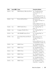
... 143. 0060h Yes HDD 0 Error See "Troubleshooting a Hard Drive" on page 123. 0061h Yes HDD 1 Error See "Troubleshooting a Hard Drive" on page 123. 0062h Yes HDD 2 Error See "Troubleshooting a Hard Drive" on page 123. 0063h Yes HDD 3 Error See "Troubleshooting a Hard Drive" on page 123. 0064h Yes HDD 4 Error See "Troubleshooting a Hard Drive" on page 123. 0065h Yes HDD 5 Error...
... 143. 0060h Yes HDD 0 Error See "Troubleshooting a Hard Drive" on page 123. 0061h Yes HDD 1 Error See "Troubleshooting a Hard Drive" on page 123. 0062h Yes HDD 2 Error See "Troubleshooting a Hard Drive" on page 123. 0063h Yes HDD 3 Error See "Troubleshooting a Hard Drive" on page 123. 0064h Yes HDD 4 Error See "Troubleshooting a Hard Drive" on page 123. 0065h Yes HDD 5 Error...

Hardware Owner's Manual
Page 26
...ATAPI 1 Error 0082h Yes ATAPI 2 Error 0083h Yes ATAPI 3 Error 0084h Yes ATAPI 4 Error 0085h Yes ATAPI 5 Error Corrective Actions See "Troubleshooting a Hard Drive" on page 143. If the problem persists, see "Getting Help" on page 123. Remove AC power to the system for 10 seconds and restart the... power to the system for 10 seconds and restart the system. If the problem persists, see "Getting Help" on page 143. See "Troubleshooting a Hard Drive" on page 143. If the problem persists, see "Getting Help" on page 143. If the problem persists, see "Getting Help" on page 123...
...ATAPI 1 Error 0082h Yes ATAPI 2 Error 0083h Yes ATAPI 3 Error 0084h Yes ATAPI 4 Error 0085h Yes ATAPI 5 Error Corrective Actions See "Troubleshooting a Hard Drive" on page 143. If the problem persists, see "Getting Help" on page 123. Remove AC power to the system for 10 seconds and restart the... power to the system for 10 seconds and restart the system. If the problem persists, see "Getting Help" on page 143. See "Troubleshooting a Hard Drive" on page 143. If the problem persists, see "Getting Help" on page 143. If the problem persists, see "Getting Help" on page 123...

Hardware Owner's Manual
Page 35
Hard drives, diskette drives, and peripherals - Items that are not in brackets are prompted to make changes to the Setup utility • When redefining the communication ports to prevent ...
Hard drives, diskette drives, and peripherals - Items that are not in brackets are prompted to make changes to the Setup utility • When redefining the communication ports to prevent ...
Hardware Owner's Manual
Page 44
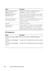
... Auto, USB devices, which are less than 530 MB are emulated as floppy and others are be used to force a formatted hard drive to boot as hard disk. This is a work around for the USB mass storage device after the start Unit command is issued. Forced FDD option ... sec default) Device# Emulation Type (Auto default) Description Configures the USB 2.0 controller in HiSpeed (480 Mbps) or FullSpeed (12 Mbps). ZIP drive) PCI Configuration Option Description NIC Function Support (PXE NIC Function Disable or PXE/iSCSI Support default) NIC1 Option ROM (Enable Set OnBoard 82576EB Disable/...
... Auto, USB devices, which are less than 530 MB are emulated as floppy and others are be used to force a formatted hard drive to boot as hard disk. This is a work around for the USB mass storage device after the start Unit command is issued. Forced FDD option ... sec default) Device# Emulation Type (Auto default) Description Configures the USB 2.0 controller in HiSpeed (480 Mbps) or FullSpeed (12 Mbps). ZIP drive) PCI Configuration Option Description NIC Function Support (PXE NIC Function Disable or PXE/iSCSI Support default) NIC1 Option ROM (Enable Set OnBoard 82576EB Disable/...

Hardware Owner's Manual
Page 45
... Configures the settings during the POST, which decreases boot up time. Specifies the boot device priority sequence from the available hard drives. Boot Settings Configuration Option Quick Boot (Enabled default) Quiet Boot (Disabled default) Wait For 'F1' If Error (Disabled default...the supervisor password is installed or not. Specifies the boot device priority. Specifies the boot device priority sequence from the available CD/DVD drives. Using the System Setup Program 45 Enables or disables this item: • Disabled: displays normal POST messages. • Enabled: displays...
... Configures the settings during the POST, which decreases boot up time. Specifies the boot device priority sequence from the available hard drives. Boot Settings Configuration Option Quick Boot (Enabled default) Quiet Boot (Disabled default) Wait For 'F1' If Error (Disabled default...the supervisor password is installed or not. Specifies the boot device priority. Specifies the boot device priority sequence from the available CD/DVD drives. Using the System Setup Program 45 Enables or disables this item: • Disabled: displays normal POST messages. • Enabled: displays...

Hardware Owner's Manual
Page 54
...may only be operated with 3.5-inch hard drives. Inside the System 1 2 3 4 5 6 1 system board assembly (4) 3 power distribution board (2) 5 hard-drive bay 2 power supply (2) 4 cooling fan (4) 6 hard drive (12) 54 Installing System Components ...Figure 3-1. You should only perform troubleshooting and simple repairs as directed by your product documentation, or as authorized in this section shows a system with the system cover installed to ensure proper cooling. Read and follow the safety instructions that is not authorized by Dell...
...may only be operated with 3.5-inch hard drives. Inside the System 1 2 3 4 5 6 1 system board assembly (4) 3 power distribution board (2) 5 hard-drive bay 2 power supply (2) 4 cooling fan (4) 6 hard drive (12) 54 Installing System Components ...Figure 3-1. You should only perform troubleshooting and simple repairs as directed by your product documentation, or as authorized in this section shows a system with the system cover installed to ensure proper cooling. Read and follow the safety instructions that is not authorized by Dell...

Hardware Owner's Manual
Page 55
... System Components 55 Hard Drives The installation and removal procedures for the 3.5-inch hard drive and the 2.5-inch hard drive are similar. Following is applicable to systems with the drive bay and insert the blank into the drive bay until it is free of a 3.5-inch hard drive. Removing a Hard-Drive Blank CAUTION: To maintain proper system cooling, all empty hard-drive bays must have...
... System Components 55 Hard Drives The installation and removal procedures for the 3.5-inch hard drive and the 2.5-inch hard drive are similar. Following is applicable to systems with the drive bay and insert the blank into the drive bay until it is free of a 3.5-inch hard drive. Removing a Hard-Drive Blank CAUTION: To maintain proper system cooling, all empty hard-drive bays must have...

Hardware Owner's Manual
Page 56
... 56 Installing System Components Read and follow the safety instructions that is not authorized by Dell is not covered by a certified service technician. Removing a Hard-Drive Carrier CAUTION: Many repairs may only be done by your product documentation, or as authorized in your warranty. Damage due to servicing that came... troubleshooting and simple repairs as directed by the online or telephone service and support team. See Figure 3-3. 3 Using the release handle, pull the hard-drive carrier out of the hard-drive bay. CAUTION: To maintain proper system cooling, all empty...
... 56 Installing System Components Read and follow the safety instructions that is not authorized by Dell is not covered by a certified service technician. Removing a Hard-Drive Carrier CAUTION: Many repairs may only be done by your product documentation, or as authorized in your warranty. Damage due to servicing that came... troubleshooting and simple repairs as directed by the online or telephone service and support team. See Figure 3-3. 3 Using the release handle, pull the hard-drive carrier out of the hard-drive bay. CAUTION: To maintain proper system cooling, all empty...

Hardware Owner's Manual
Page 57
... may only be done by the online or telephone service and support team. See Figure 3-4. 2 Lift the hard drive out of the hard-drive carrier. CAUTION: To prevent data loss, ensure that is not authorized by Dell is not supported. Damage due to a partially installed carrier can damage the partially installed carrier's shield spring and...
... may only be done by the online or telephone service and support team. See Figure 3-4. 2 Lift the hard drive out of the hard-drive carrier. CAUTION: To prevent data loss, ensure that is not authorized by Dell is not supported. Damage due to a partially installed carrier can damage the partially installed carrier's shield spring and...

Hardware Owner's Manual
Page 58
... by Dell is not covered by a certified service technician. See Figure 3-4. 2 Secure the hard drive to servicing that came with four screws. Figure 3-4. Damage due to the hard-drive carrier with the product. 1 Place the hard drive into the hard-drive carrier. See Figure 3-4. 58 Installing System Components Removing and Installing a Hard Drive from the Hard-Drive Carrier 1 2 3 1 hard drive 3 hard-drive carrier 2 screw (4) Installing a Hard Drive Into a Hard-Drive Carrier...
... by Dell is not covered by a certified service technician. See Figure 3-4. 2 Secure the hard drive to servicing that came with four screws. Figure 3-4. Damage due to the hard-drive carrier with the product. 1 Place the hard drive into the hard-drive carrier. See Figure 3-4. 58 Installing System Components Removing and Installing a Hard Drive from the Hard-Drive Carrier 1 2 3 1 hard drive 3 hard-drive carrier 2 screw (4) Installing a Hard Drive Into a Hard-Drive Carrier...

Hardware Owner's Manual
Page 59
...Full configuration Up to two Up to two processors, nine processors, nine hard hard drives, and nine drives, and nine memory modules memory modules Up to two Up to two N/A processors, six hard processors, six hard drives, and nine drives, and four memory modules memory modules Up to two N/A N/A processors...servicing that came with the product. Power Supplies Table 3-1. Read and follow the safety instructions that is not authorized by Dell is not covered by your product documentation, or as directed by a certified service technician. You should only perform troubleshooting and...
...Full configuration Up to two Up to two processors, nine processors, nine hard hard drives, and nine drives, and nine memory modules memory modules Up to two Up to two N/A processors, six hard processors, six hard drives, and nine drives, and four memory modules memory modules Up to two N/A N/A processors...servicing that came with the product. Power Supplies Table 3-1. Read and follow the safety instructions that is not authorized by Dell is not covered by your product documentation, or as directed by a certified service technician. You should only perform troubleshooting and...


