Hardware Owner's Manual
Page 6
... the SAS Mezzanine Card 75 Removing the Infiniband Mezzanine Card . . . . . 76 Installing the Infiniband Mezzanine Card. . . . . . 77 System Memory 77 Supported DIMM Configuration 77 Removing Memory Modules 79 Installing Memory Modules 80 Interposer Extenders 82 Removing the Interposer Extender 82 Installing ...Replacing the System Battery 84 RAID Battery (Optional 85 Removing the RAID Battery 85 Installing the RAID Battery 86 Removing the RAID Battery Carrier 87 Installing the RAID Battery Carrier 88 System Board 89 Removing a System Board 89 Installing a System Board 90 ...
... the SAS Mezzanine Card 75 Removing the Infiniband Mezzanine Card . . . . . 76 Installing the Infiniband Mezzanine Card. . . . . . 77 System Memory 77 Supported DIMM Configuration 77 Removing Memory Modules 79 Installing Memory Modules 80 Interposer Extenders 82 Removing the Interposer Extender 82 Installing ...Replacing the System Battery 84 RAID Battery (Optional 85 Removing the RAID Battery 85 Installing the RAID Battery 86 Removing the RAID Battery Carrier 87 Installing the RAID Battery Carrier 88 System Board 89 Removing a System Board 89 Installing a System Board 90 ...
Hardware Owner's Manual
Page 7
... Distribution Board 94 Installing a Power Distribution Board 96 Fan Controller Board 97 Installing the Fan Controller Board 98 Midplanes 99 Removing the Midplanes 99 Installing the Midplanes 104 Backplanes 105 Removing the Backplane 105 Installing the Backplane 108 Front Panels 109 Removing the Front Panel 109 Installing Front Panel 111 4 Troubleshooting Your System 113 Safety...
... Distribution Board 94 Installing a Power Distribution Board 96 Fan Controller Board 97 Installing the Fan Controller Board 98 Midplanes 99 Removing the Midplanes 99 Installing the Midplanes 104 Backplanes 105 Removing the Backplane 105 Installing the Backplane 108 Front Panels 109 Removing the Front Panel 109 Installing Front Panel 111 4 Troubleshooting Your System 113 Safety...
Hardware Owner's Manual
Page 92
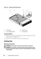
Figure 3-22. Cooling Fans Removing a Cooling Fan WARNING: Do not attempt to the front of the chassis until it snaps into place. Opening and Closing the System 1 2 3 4 1 traction pad 3 cover release latch .... 92 Installing System Components Allow time for some time after the system has been powered down. WARNING: The cooling fan can continue to spin for the fan to stop spinning before removing it to operate the system without the cooling fans. See Figure 3-22. 2 Secure the cover with the securing screw. See Figure 3-22.
Figure 3-22. Cooling Fans Removing a Cooling Fan WARNING: Do not attempt to the front of the chassis until it snaps into place. Opening and Closing the System 1 2 3 4 1 traction pad 3 cover release latch .... 92 Installing System Components Allow time for some time after the system has been powered down. WARNING: The cooling fan can continue to spin for the fan to stop spinning before removing it to operate the system without the cooling fans. See Figure 3-22. 2 Secure the cover with the securing screw. See Figure 3-22.

Hardware Owner's Manual
Page 93
...authorized by Dell is not covered by your product documentation, or as you replace them from its electrical outlet. 2 Open the system. Damage due to prevent the cables from the fan-controller board. You must route these cables properly when you remove them to... should only perform troubleshooting and simple repairs as authorized in your warranty. Note the routing of the cooling-fan cage. Removing and Installing a Cooling Fan 1 2 1 cooling-fan cage 2 cooling fan (4) Installing System Components 93 CAUTION: Many repairs may only be done by the online or telephone service ...
...authorized by Dell is not covered by your product documentation, or as you replace them from its electrical outlet. 2 Open the system. Damage due to prevent the cables from the fan-controller board. You must route these cables properly when you remove them to... should only perform troubleshooting and simple repairs as authorized in your warranty. Note the routing of the cooling-fan cage. Removing and Installing a Cooling Fan 1 2 1 cooling-fan cage 2 cooling fan (4) Installing System Components 93 CAUTION: Many repairs may only be done by the online or telephone service ...

Hardware Owner's Manual
Page 94
... online or telephone service and support team. Read and follow the safety instructions that is not authorized by Dell is similar. See "Removing a Power Supply" on the chassis to remove and install both the power distribution boards is not covered by your warranty. See Figure 3-23. Read ...and follow the safety instructions that is not authorized by Dell is firmly seated. The procedure to prevent them from its electrical outlet and turn on the fan-controller ...
... online or telephone service and support team. Read and follow the safety instructions that is not authorized by Dell is similar. See "Removing a Power Supply" on the chassis to remove and install both the power distribution boards is not covered by your warranty. See Figure 3-23. Read ...and follow the safety instructions that is not authorized by Dell is firmly seated. The procedure to prevent them from its electrical outlet and turn on the fan-controller ...
Hardware Owner's Manual
Page 97
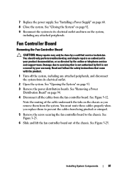
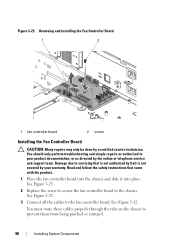
.... Installing System Components 97 Read and follow the safety instructions that is not authorized by Dell is not covered by your product documentation, or as you replace them from being pinched or crimped. 5 Remove the screw securing the fan controller board to its electrical outlet. 2 Open the system. See Figure 5-12. See "Installing...
.... Installing System Components 97 Read and follow the safety instructions that is not authorized by Dell is not covered by your product documentation, or as you replace them from being pinched or crimped. 5 Remove the screw securing the fan controller board to its electrical outlet. 2 Open the system. See Figure 5-12. See "Installing...
Hardware Owner's Manual
Page 98
... Dell is not covered by a certified service technician. See Figure 5-12. Damage due to the fan controller board. You must route these cables properly through the tabs on the chassis to the chassis. Removing and Installing the Fan Controller Board 1 2 1 fan controller board 2 screw Installing the Fan ... repairs as directed by the online or telephone service and support team. See Figure 3-25. 2 Replace the screw to secure the fan controller board to prevent them from being pinched or crimped. 98 Installing System Components Figure 3-25. See Figure 3-25. 3 Connect...
... Dell is not covered by a certified service technician. See Figure 5-12. Damage due to the fan controller board. You must route these cables properly through the tabs on the chassis to the chassis. Removing and Installing the Fan Controller Board 1 2 1 fan controller board 2 screw Installing the Fan ... repairs as directed by the online or telephone service and support team. See Figure 3-25. 2 Replace the screw to secure the fan controller board to prevent them from being pinched or crimped. 98 Installing System Components Figure 3-25. See Figure 3-25. 3 Connect...

Hardware Owner's Manual
Page 99
... due to servicing that is not authorized by Dell is not covered by the online or telephone service and support team. See "Removing a Cooling Fan" on page 96. 5 Close the system. See "Installing a Power Distribution Board" on page 92. 5 Remove the screws that came with the product. 1...directed by your warranty. See Figure 3-26. 6 Lift the cooling-fan brackets out of the chassis. See "Opening the System" on page 61. 4 Remove the cooling fans. Figure 3-26. 4 Replace the power distribution boards. Midplanes Removing the Midplanes CAUTION: Many repairs may only be done by a certified...
... due to servicing that is not authorized by Dell is not covered by the online or telephone service and support team. See "Removing a Cooling Fan" on page 96. 5 Close the system. See "Installing a Power Distribution Board" on page 92. 5 Remove the screws that came with the product. 1...directed by your warranty. See Figure 3-26. 6 Lift the cooling-fan brackets out of the chassis. See "Opening the System" on page 61. 4 Remove the cooling fans. Figure 3-26. 4 Replace the power distribution boards. Midplanes Removing the Midplanes CAUTION: Many repairs may only be done by a certified...

Hardware Owner's Manual
Page 100
... underneath the tabs on the chassis as you replace them from the system. Figure 3-27. 100 Installing System Components Removing and Installing the Cooling-Fan Brackets 1 2 3 1 cooling fan bracket (long) 3 cooling fan bracket (short) 2 screw (14) 7 Remove the screws that secure the upper midplane to prevent the cables from the upper midplane. Figure 3-27. 8 Disconnect...
... underneath the tabs on the chassis as you replace them from the system. Figure 3-27. 100 Installing System Components Removing and Installing the Cooling-Fan Brackets 1 2 3 1 cooling fan bracket (long) 3 cooling fan bracket (short) 2 screw (14) 7 Remove the screws that secure the upper midplane to prevent the cables from the upper midplane. Figure 3-27. 8 Disconnect...

Hardware Owner's Manual
Page 105
...the midplane to the chassis. See Figure 3-28. 8 Place the upper midplane on page 56. Figure 3-27. 10 Connect all the hard drives. See "Removing a Hard-Drive Carrier" on the midplane holder. See "Installing a System-Board Assembly" on page 62. 15 Close the system, see "Closing the System"... page 92. 16 Reconnect the system to the upper midplane. Figure 3-26. 13 Replace the cooling fans. Damage due to servicing that is not authorized by Dell is similar to the chassis. See Figure 5-9. 7 Replace the screws that secure the mid-plane holder support to backplane for 2.5-inch ...
...the midplane to the chassis. See Figure 3-28. 8 Place the upper midplane on page 56. Figure 3-27. 10 Connect all the hard drives. See "Removing a Hard-Drive Carrier" on the midplane holder. See "Installing a System-Board Assembly" on page 62. 15 Close the system, see "Closing the System"... page 92. 16 Reconnect the system to the upper midplane. Figure 3-26. 13 Replace the cooling fans. Damage due to servicing that is not authorized by Dell is similar to the chassis. See Figure 5-9. 7 Replace the screws that secure the mid-plane holder support to backplane for 2.5-inch ...
Hardware Owner's Manual
Page 107
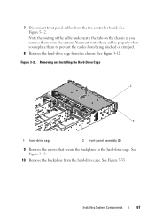
You must route these cables properly when you remove them to the hard-drive cage. See Figure 3-33. Note the routing of the cable underneath the tabs on the chassis as you replace them .... See Figure 3-32. Figure 3-32. Installing System Components 107 See Figure 3-33. 10 Remove the backplane from the system. 7 Disconnect front panel cables from the chassis. Removing and Installing the Hard-Drive Cage 1 2 1 hard-drive cage 2 front-panel assembly (2) 9 Remove the screws that secure the backplane to prevent the cables from being pinched...
You must route these cables properly when you remove them to the hard-drive cage. See Figure 3-33. Note the routing of the cable underneath the tabs on the chassis as you replace them .... See Figure 3-32. Figure 3-32. Installing System Components 107 See Figure 3-33. 10 Remove the backplane from the system. 7 Disconnect front panel cables from the chassis. Removing and Installing the Hard-Drive Cage 1 2 1 hard-drive cage 2 front-panel assembly (2) 9 Remove the screws that secure the backplane to prevent the cables from being pinched...
Hardware Owner's Manual
Page 109
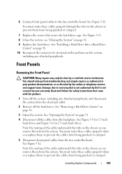
...58. 10 Reconnect the system to prevent the cables from being pinched or crimped. 5 Disconnect front panel cables from the fan controller board. Front Panels Removing the Front Panel CAUTION: Many repairs may only be done by the online or telephone service and support team. See ...the cables from being pinched or crimped. You must route these cables properly when you remove them to the fan controller board. Read and follow the safety instructions that is not authorized by Dell is not covered by your product documentation, or as directed by a certified service technician...
...58. 10 Reconnect the system to prevent the cables from being pinched or crimped. 5 Disconnect front panel cables from the fan controller board. Front Panels Removing the Front Panel CAUTION: Many repairs may only be done by the online or telephone service and support team. See ...the cables from being pinched or crimped. You must route these cables properly when you remove them to the fan controller board. Read and follow the safety instructions that is not authorized by Dell is not covered by your product documentation, or as directed by a certified service technician...

Hardware Owner's Manual
Page 117
...starts properly, shut down the system and reinstall the expansion card that is not authorized by Dell is not covered by the online or telephone service and support team. You should only perform... attached peripherals, and disconnect the system from the system. Damage due to servicing that you removed in your product documentation, or as directed by your warranty. See "Opening the System" on...Hard drives • SAS backplane • Expansion-card • Power supplies • Fans • Processors and heat sinks • Memory modules 4 Let the system dry thoroughly for at least...
...starts properly, shut down the system and reinstall the expansion card that is not authorized by Dell is not covered by the online or telephone service and support team. You should only perform... attached peripherals, and disconnect the system from the system. Damage due to servicing that you removed in your product documentation, or as directed by your warranty. See "Opening the System" on...Hard drives • SAS backplane • Expansion-card • Power supplies • Fans • Processors and heat sinks • Memory modules 4 Let the system dry thoroughly for at least...
Hardware Owner's Manual
Page 120
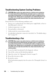
... due to servicing that came with the product. See "Closing the System" on page 91. 4 Reseat the fan's power cable. 5 Restart the system. Ensure that is not authorized by Dell is not covered by the diagnostic software. 2 Turn off the system and all attached peripherals. 3 Open the ... is too high. • External airflow is obstructed. • Cables inside the system obstruct airflow. • An individual cooling fan is removed or has failed. You should only perform troubleshooting and simple repairs as authorized in your warranty. Read and follow the safety instructions that...
... due to servicing that came with the product. See "Closing the System" on page 91. 4 Reseat the fan's power cable. 5 Restart the system. Ensure that is not authorized by Dell is not covered by the diagnostic software. 2 Turn off the system and all attached peripherals. 3 Open the ... is too high. • External airflow is obstructed. • Cables inside the system obstruct airflow. • An individual cooling fan is removed or has failed. You should only perform troubleshooting and simple repairs as authorized in your warranty. Read and follow the safety instructions that...

Hardware Owner's Manual
Page 121
... may only be done by your system to power. 2 Turn on the system and attached peripherals and note the messages on the screen. See "Removing a System-Board Assembly" on page 92. See "Closing the System" on page 61. Damage due to step 13 if an error message appears .... Go to servicing that is not authorized by Dell is still indicated, go to the memory settings, if needed. 6 If the fan does not function, turn off the system and attached peripherals, and unplug the system from the electrical outlet. 5 Remove the system-board assembly. Troubleshooting Your System 121 NOTE...
... may only be done by your system to power. 2 Turn on the system and attached peripherals and note the messages on the screen. See "Removing a System-Board Assembly" on page 92. See "Closing the System" on page 61. Damage due to step 13 if an error message appears .... Go to servicing that is not authorized by Dell is still indicated, go to the memory settings, if needed. 6 If the fan does not function, turn off the system and attached peripherals, and unplug the system from the electrical outlet. 5 Remove the system-board assembly. Troubleshooting Your System 121 NOTE...
Hardware Owner's Manual
Page 155
..., 124 battery (system) replacing, 84 blank hard drive, 55 C collecting system event log, 23 contacting Dell, 143 cooling fans installing, 94 removing, 92 troubleshooting, 120 cooling shroud installing, 64 removing, 63 D damaged systems troubleshooting, 118 Dell contacting, 143 drive blank installing, 55 removing, 55 E expansion card installing, 71 removing, 69 troubleshooting, 125 expansion card connector installing, 74...
..., 124 battery (system) replacing, 84 blank hard drive, 55 C collecting system event log, 23 contacting Dell, 143 cooling fans installing, 94 removing, 92 troubleshooting, 120 cooling shroud installing, 64 removing, 63 D damaged systems troubleshooting, 118 Dell contacting, 143 drive blank installing, 55 removing, 55 E expansion card installing, 71 removing, 69 troubleshooting, 125 expansion card connector installing, 74...
Hardware Owner's Manual
Page 156
F fan controller board removing, 97-98 features and indicators front panel, 12 front panel installing, 111 front panel removing, 109 front-panel features, 12 H hard drive installing hot-swap hard drive, 57-58 removing, 56 removing a hot-swap hard drive, 56 troubleshooting, 123 heat sink installing, 66 heat sink removing, 64 heat sinks installing, 66 removing, 64 I indicator codes AC power, 21 hard-drive tray, 18 NIC, 19 NIC (KVM over IP port), 19 NIC speed (KVM over IP port), 19 power and system board, 20 indicators back panel, 16 156 Index
F fan controller board removing, 97-98 features and indicators front panel, 12 front panel installing, 111 front panel removing, 109 front-panel features, 12 H hard drive installing hot-swap hard drive, 57-58 removing, 56 removing a hot-swap hard drive, 56 troubleshooting, 123 heat sink installing, 66 heat sink removing, 64 heat sinks installing, 66 removing, 64 I indicator codes AC power, 21 hard-drive tray, 18 NIC, 19 NIC (KVM over IP port), 19 NIC speed (KVM over IP port), 19 power and system board, 20 indicators back panel, 16 156 Index
Hardware Owner's Manual
Page 157
front panel, 12 installing backplanes, 108 cooling fans, 94 cooling shroud, 64 expansion card, 71 expansion card connector, 74 front panel, 111 hard drive blank, 55 heat sink, 66 heat sinks, 66 hot-..., 83 memory modules, 80 mezzanine card, 76 midplanes, 104 power supply, 60 processor, 68 system board, 90 system board assembly, 62 interposer extender installing, 83 removing, 82 K keyboards troubleshooting, 114 L LEDs front of the system, 22 M memory troubleshooting, 121 memory modules (DIMMs) configuring, 77 installing, 80...
front panel, 12 installing backplanes, 108 cooling fans, 94 cooling shroud, 64 expansion card, 71 expansion card connector, 74 front panel, 111 hard drive blank, 55 heat sink, 66 heat sinks, 66 hot-..., 83 memory modules, 80 mezzanine card, 76 midplanes, 104 power supply, 60 processor, 68 system board, 90 system board assembly, 62 interposer extender installing, 83 removing, 82 K keyboards troubleshooting, 114 L LEDs front of the system, 22 M memory troubleshooting, 121 memory modules (DIMMs) configuring, 77 installing, 80...

Hardware Owner's Manual
Page 158
removing, 66 processors troubleshooting, 126 R removing backplanes, 105 cooling fans, 92 expansion card, 69 expansion card connector, 72 fan controller board, 97-98 front panel, 109 hard drive, 56 hard drive blank, 55 heat sink, 64 heat sinks, 64 hot-swap hard drive, 56 interposer extender, 82 memory modules (DIMMs), 82 mezzanine card, 74 midplanes, 99 power distribution board, 94 power supply, 59 processor, 66 system board, 89 system board assembly, 61 replacing system battery, 84 S safety, 53, 113 SAS controller daughter card 158 Index
removing, 66 processors troubleshooting, 126 R removing backplanes, 105 cooling fans, 92 expansion card, 69 expansion card connector, 72 fan controller board, 97-98 front panel, 109 hard drive, 56 hard drive blank, 55 heat sink, 64 heat sinks, 64 hot-swap hard drive, 56 interposer extender, 82 memory modules (DIMMs), 82 mezzanine card, 74 midplanes, 99 power distribution board, 94 power supply, 59 processor, 66 system board, 89 system board assembly, 61 replacing system battery, 84 S safety, 53, 113 SAS controller daughter card 158 Index

Hardware Owner's Manual
Page 159
... troubleshooting, 124 startup accessing system features, 11 support contacting Dell, 143 system closing, 92 opening, 91 system board connectors, 129 installing, 90 jumper settings, 139 removing, 89 system board assembly installing, 62 removing, 61 system cooling troubleshooting, 120 system features accessing, 11... configuration, 48 subnet mask configuration, 51 system memory, 38 USB configuration, 43 T telephone numbers, 143 troubleshooting battery, 118 cooling fans, 120 damaged system, 118 expansion card, 125 external connections, 114 hard drive, 123 keyboard, 114 memory, 121 NIC, 116 ...
... troubleshooting, 124 startup accessing system features, 11 support contacting Dell, 143 system closing, 92 opening, 91 system board connectors, 129 installing, 90 jumper settings, 139 removing, 89 system board assembly installing, 62 removing, 61 system cooling troubleshooting, 120 system features accessing, 11... configuration, 48 subnet mask configuration, 51 system memory, 38 USB configuration, 43 T telephone numbers, 143 troubleshooting battery, 118 cooling fans, 120 damaged system, 118 expansion card, 125 external connections, 114 hard drive, 123 keyboard, 114 memory, 121 NIC, 116 ...


