
Glossary
Page 2
... power indicator. A chip or expansion card that allows the processor to perform remote, or "out-ofband," server management on your network server using a remote access controller. See processor. A technology in memory modules that plugs into an expansion-card connector on both the rising and falling pulses of data between the processor and memory or between the expansion bus and a peripheral. 2 See device driver. ERA allows you to communicate with a peripheral. DC - Domain Name System. Error checking and correction. control panel - diagnostics...
... power indicator. A chip or expansion card that allows the processor to perform remote, or "out-ofband," server management on your network server using a remote access controller. See processor. A technology in memory modules that plugs into an expansion-card connector on both the rising and falling pulses of data between the processor and memory or between the expansion bus and a peripheral. 2 See device driver. ERA allows you to communicate with a peripheral. DC - Domain Name System. Error checking and correction. control panel - diagnostics...

Glossary
Page 3
... device, and a monitor is usually rounded to insert or install a device, typically a hard drive or an internal cooling fan, into the host system while the system is the data path and physical interface between the system's bus and the peripheral device, typically a storage device. In general, I /O - Integrated drive electronics. Integrated Dell Remote Access Controller. InfiniBand - Internet Protocol. A high-speed network interface used by z colors. FTP - Gram(s). hot-plug - IDE - iDRAC - Fahrenheit. The FSB is powered...
... device, and a monitor is usually rounded to insert or install a device, typically a hard drive or an internal cooling fan, into the host system while the system is the data path and physical interface between the system's bus and the peripheral device, typically a storage device. In general, I /O - Integrated drive electronics. Integrated Dell Remote Access Controller. InfiniBand - Internet Protocol. A high-speed network interface used by z colors. FTP - Gram(s). hot-plug - IDE - iDRAC - Fahrenheit. The FSB is powered...

Glossary
Page 5
... to serve specific storage needs. memory key - MHz - A portable flash memory storage device integrated with a USB connector. A type of data redundancy in a system to allow connection to remotely manage one of the data. mm - NAS systems have their own operating systems, integrated hardware, and software that stores basic system data. management station - Megabyte(s); 1,048,576 bytes. Managed object format is an ASCII file that is monitored and managed using Dell OpenManage™ Server Administrator. Network interface controller. Your system...
... to serve specific storage needs. memory key - MHz - A portable flash memory storage device integrated with a USB connector. A type of data redundancy in a system to allow connection to remotely manage one of the data. mm - NAS systems have their own operating systems, integrated hardware, and software that stores basic system data. management station - Megabyte(s); 1,048,576 bytes. Managed object format is an ASCII file that is monitored and managed using Dell OpenManage™ Server Administrator. Network interface controller. Your system...

Glossary
Page 6
... RAID arrays, a striped hard drive containing parity data. PCI - PERC - pixel - A single point on self-test. A video resolution, such as 640 x 480, is a synonym for local-bus implementation. Power-on a video display. Before the operating system loads when you turn on another processor. CPU is expressed as RAM and hard drives. Preboot eXecution Environment. RAC - ns - An internal or external device, such as a diskette drive or keyboard, connected to signal the processor about hardware errors. POST - processor - PXE - A device...
... RAID arrays, a striped hard drive containing parity data. PCI - PERC - pixel - A single point on self-test. A video resolution, such as 640 x 480, is a synonym for local-bus implementation. Power-on a video display. Before the operating system loads when you turn on another processor. CPU is expressed as RAM and hard drives. Preboot eXecution Environment. RAC - ns - An internal or external device, such as a diskette drive or keyboard, connected to signal the processor about hardware errors. POST - processor - PXE - A device...

Glossary
Page 7
... you turn off your system. RAID on the screen. 7 SAS - Serial-attached SCSI. SEL - A legacy I /O bus interface with software or hardware, that enables remote networkattached storage devices to appear to a server to the system. Redundant array of providing data redundancy. Any information stored in RAM is most often used to the system BIOS and then display an error message on motherboard. Examples of RAID include RAID 0, RAID 1, RAID 5, RAID 10, and RAID 50. SATA - Small computer system interface. sec - Second(s). service...
... you turn off your system. RAID on the screen. 7 SAS - Serial-attached SCSI. SEL - A legacy I /O bus interface with software or hardware, that enables remote networkattached storage devices to appear to a server to the system. Redundant array of providing data redundancy. Any information stored in RAM is most often used to the system BIOS and then display an error message on motherboard. Examples of RAID include RAID 0, RAID 1, RAID 5, RAID 10, and RAID 50. SATA - Small computer system interface. sec - Second(s). service...

Glossary
Page 8
... automatically supplies power to other hubs or switches without requiring a crossover cable. Because the System Setup program is installed and how the system should be connected and disconnected while the system is the same on each processor has equal access to remotely monitor and manage workstations. uplink port - SMP - Symmetric multiprocessing. SNMP - Simple Network Management Protocol. Disk striping writes data across three or more processors connected via a high-bandwidth link and managed by...
... automatically supplies power to other hubs or switches without requiring a crossover cable. Because the System Setup program is installed and how the system should be connected and disconnected while the system is the same on each processor has equal access to remotely monitor and manage workstations. uplink port - SMP - Symmetric multiprocessing. SNMP - Simple Network Management Protocol. Disk striping writes data across three or more processors connected via a high-bandwidth link and managed by...
User Manual
Page 5
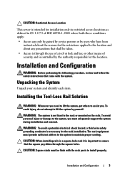
... system. CAUTION: When installing rails in Cl. 1.2.7.3 of security, and is controlled by the authority responsible for the location. Installation and Configuration WARNING: Before performing the following procedure, review and follow the safety instructions that came with the rack posts to the location and about any precautions that the square peg slides through the use of a tool or lock and key, or other means...
... system. CAUTION: When installing rails in Cl. 1.2.7.3 of security, and is controlled by the authority responsible for the location. Installation and Configuration WARNING: Before performing the following procedure, review and follow the safety instructions that came with the rack posts to the location and about any precautions that the square peg slides through the use of a tool or lock and key, or other means...

Hardware Owner's Manual
Page 6
... Counterclockwise 90°) 4 2 1 3 2 1 Item Feature 1 VGA/USB connector 2 NIC LAN ports 3 Power button 4 Mezzanine card cover Description VGA/USB 2.0 connector 10/100/1 GB NIC LAN connector 1 10/100/1 GB NIC LAN connector 2 On/Off button for sled Cover for the PowerEdge C5220 server, an eight sled SKU and a twelve sled SKU. For information on sled population, see "Sled Configuration" on page 51. Front-Panel Features and Indicators The Dell PowerEdge C5220 server is available in either a single-width...
... Counterclockwise 90°) 4 2 1 3 2 1 Item Feature 1 VGA/USB connector 2 NIC LAN ports 3 Power button 4 Mezzanine card cover Description VGA/USB 2.0 connector 10/100/1 GB NIC LAN connector 1 10/100/1 GB NIC LAN connector 2 On/Off button for sled Cover for the PowerEdge C5220 server, an eight sled SKU and a twelve sled SKU. For information on sled population, see "Sled Configuration" on page 51. Front-Panel Features and Indicators The Dell PowerEdge C5220 server is available in either a single-width...

Hardware Owner's Manual
Page 25
... of detected SATA hard drives. Disable/Enable the feature that allows SATA hard drives to initiate link power management transitions. While entering setup, BIOS auto detects the presence of SATA devices and displays the status of detected SATA hard drives. While entering setup, BIOS auto detects the presence of SATA devices and displays the status of detected SATA hard drives. Not Set Security Freeze Lock Command Using the System Setup Program 25 While entering setup, BIOS auto detects the presence of SATA devices and displays the status of detected SATA hard drives. Menu...
... of detected SATA hard drives. Disable/Enable the feature that allows SATA hard drives to initiate link power management transitions. While entering setup, BIOS auto detects the presence of SATA devices and displays the status of detected SATA hard drives. While entering setup, BIOS auto detects the presence of SATA devices and displays the status of detected SATA hard drives. Not Set Security Freeze Lock Command Using the System Setup Program 25 While entering setup, BIOS auto detects the presence of SATA devices and displays the status of detected SATA hard drives. Menu...
Hardware Owner's Manual
Page 28
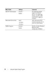
Auto detects the PCIe maximum payload size or sets it to 128/256 Bytes. To enable this feature, an add-on NIC with SR-IOV support is required. Enable or disable Windows Hardware Error Architecture (WHEA) 28 Using the System Setup Program Menu Fields SR-IOV Global Enable Settings Disable* Enable Maximum Payload Size WHEA Support Auto* 128 Bytes 256 Bytes Disable* Enable Comments Disable/Enable BIOS support for SR-IOV devices.
Auto detects the PCIe maximum payload size or sets it to 128/256 Bytes. To enable this feature, an add-on NIC with SR-IOV support is required. Enable or disable Windows Hardware Error Architecture (WHEA) 28 Using the System Setup Program Menu Fields SR-IOV Global Enable Settings Disable* Enable Maximum Payload Size WHEA Support Auto* 128 Bytes 256 Bytes Disable* Enable Comments Disable/Enable BIOS support for SR-IOV devices.

Hardware Owner's Manual
Page 35
Select to configure LAN channel parameters statically or dynamically (DHCP). Set BMC LAN Configuration Menu Fields Settings Server Management/BMC Network Configuration BMC LAN Port Configuration Dedicated-NIC Shared-NIC* BMC NIC IP Source Static DHCP* Comments BMC LAN Port Configuration NOTE: Dedicated-NIC port is found on the chassis. Using the System Setup Program 35
Select to configure LAN channel parameters statically or dynamically (DHCP). Set BMC LAN Configuration Menu Fields Settings Server Management/BMC Network Configuration BMC LAN Port Configuration Dedicated-NIC Shared-NIC* BMC NIC IP Source Static DHCP* Comments BMC LAN Port Configuration NOTE: Dedicated-NIC port is found on the chassis. Using the System Setup Program 35

Hardware Owner's Manual
Page 37
Client console utility should have the same or compatible settings. Using the System Setup Program 37 Both systems should be supported. NOTE: The screen would keep 100x31 even when Remote Access is enabled. Remote Access Configuration Menu Fields Settings Server/Remote Access Configuration Remote Access Disabled Enabled* Comments The settings specify how the host and remote systems exchanges data.
Client console utility should have the same or compatible settings. Using the System Setup Program 37 Both systems should be supported. NOTE: The screen would keep 100x31 even when Remote Access is enabled. Remote Access Configuration Menu Fields Settings Server/Remote Access Configuration Remote Access Disabled Enabled* Comments The settings specify how the host and remote systems exchanges data.
Hardware Owner's Manual
Page 38
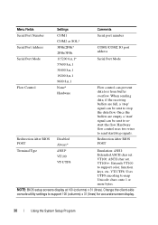
... Comments Serial Port Number COM1 Serial port number COM2 as SOL* Serial Port Address 3F8h/2F8h* 2F8h/3F8h COM1/COM2 IO port address Serial Port Mode 115200 8,n,1* Serial Port Mode 57600 8,n,1 38400 8,n,1 19200 8,n,1 9600 8,n,1 Flow Control None* Hardware Flow control can be sent to restart the flow. Redirection After BIOS POST Disabled Always* Redirection After BIOS POST Terminal Type ANSI* VT100 VT-UTF8 Emulation: ANSI: Extended ASCII char set . Change the client-side console utility settings to support color, function keys, etc. Hardware flow control uses...
... Comments Serial Port Number COM1 Serial port number COM2 as SOL* Serial Port Address 3F8h/2F8h* 2F8h/3F8h COM1/COM2 IO port address Serial Port Mode 115200 8,n,1* Serial Port Mode 57600 8,n,1 38400 8,n,1 19200 8,n,1 9600 8,n,1 Flow Control None* Hardware Flow control can be sent to restart the flow. Redirection After BIOS POST Disabled Always* Redirection After BIOS POST Terminal Type ANSI* VT100 VT-UTF8 Emulation: ANSI: Extended ASCII char set . Change the client-side console utility settings to support color, function keys, etc. Hardware flow control uses...
Hardware Owner's Manual
Page 71
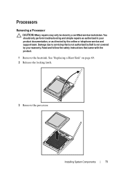
You should only perform troubleshooting and simple repairs as directed by a certified service technician. Installing System Components 71 See "Replacing a Heat Sink" on page 69. 2 Release the locking latch. 3 Remove the processor. Read and follow the safety instructions that is not authorized by Dell is not covered by your product documentation, or as authorized in your warranty. Processors Removing a Processor CAUTION: Many repairs may only be done...
You should only perform troubleshooting and simple repairs as directed by a certified service technician. Installing System Components 71 See "Replacing a Heat Sink" on page 69. 2 Release the locking latch. 3 Remove the processor. Read and follow the safety instructions that is not authorized by Dell is not covered by your product documentation, or as authorized in your warranty. Processors Removing a Processor CAUTION: Many repairs may only be done...

Hardware Owner's Manual
Page 82
... to 60 seconds upon applying AC power to the power supply, the baseboard management controller (BMC) is initializing. Viewing System Event Logs for Investigation If the front panel LED blinks for more information, see "View BMC System Event Log" on the system. Changes to default position, covering pins 1 and 2. 7 Replace the chassis cover and turn on page 39. 82 Troubleshooting For more details). If you cannot access the BIOS Setup Utility, clear the CMOS by experienced users. If you can cause...
... to 60 seconds upon applying AC power to the power supply, the baseboard management controller (BMC) is initializing. Viewing System Event Logs for Investigation If the front panel LED blinks for more information, see "View BMC System Event Log" on the system. Changes to default position, covering pins 1 and 2. 7 Replace the chassis cover and turn on page 39. 82 Troubleshooting For more details). If you cannot access the BIOS Setup Utility, clear the CMOS by experienced users. If you can cause...
Hardware Owner's Manual
Page 83
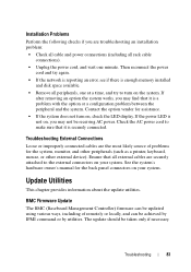
... a problem with the option or a configuration problem between the peripheral and the system. BMC Firmware Update The BMC (Baseboard Management Controller) firmware can be taken only if necessary. See the system's hardware owner's manual for assistance. • If the system does not turn on your system. Contact the option vendor for the back panel connectors on the system. If the power LED is securely connected. Troubleshooting 83 If after removing an...
... a problem with the option or a configuration problem between the peripheral and the system. BMC Firmware Update The BMC (Baseboard Management Controller) firmware can be taken only if necessary. See the system's hardware owner's manual for assistance. • If the system does not turn on your system. Contact the option vendor for the back panel connectors on the system. If the power LED is securely connected. Troubleshooting 83 If after removing an...
Hardware Owner's Manual
Page 92
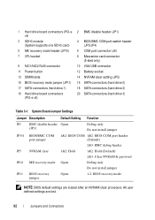
... Hold (Default) 2&3: Clear NVRAM & password JP10 ME recovery mode Open Debug only Do not install jumper JP11 BIOS recovery jumper Open 1-2: BIOS recovery mode NOTE: BIOS default settings are lost. 92 Jumpers and Connectors 1 Hard drive board connectors (PCI-e x4) 3 SDHC module (System supports one SDHC card) 5 ME recovery mode header (JP10) 7 CPU socket 9 NIC1/NIC2 RJ45 connector 11 Power button 13 DIMM slots 15 BIOS recovery mode jumper (JP11) 17 SATA connectors (hard drive 1) 19 Hard drive board connectors (PCI-e x8) 2 BMC disable header (JP1) 4 BIOS/BMC COM port switch header...
... Hold (Default) 2&3: Clear NVRAM & password JP10 ME recovery mode Open Debug only Do not install jumper JP11 BIOS recovery jumper Open 1-2: BIOS recovery mode NOTE: BIOS default settings are lost. 92 Jumpers and Connectors 1 Hard drive board connectors (PCI-e x4) 3 SDHC module (System supports one SDHC card) 5 ME recovery mode header (JP10) 7 CPU socket 9 NIC1/NIC2 RJ45 connector 11 Power button 13 DIMM slots 15 BIOS recovery mode jumper (JP11) 17 SATA connectors (hard drive 1) 19 Hard drive board connectors (PCI-e x8) 2 BMC disable header (JP1) 4 BIOS/BMC COM port switch header...

Hardware Owner's Manual
Page 103
... SAS 75 SAS cables 77 modules memory 54 O options BIOS setup 12 boot 12 P population DIMM 54 power distribution doard 97 problems installation 83 processor replacing 71 program system setup 11 R recovery BIOS 89 redirection console 12 disable 12 enable 12 removing 3.5-inch hard drive 62 a 2.5-inch hard-drive board 66 S screens server setup 15 setup 15 setup program using 11 sled configuration 51 removing 52 start menu start 11 support services 99 system inside 50 T tools recommended 49 troubleshooting 79 connections 83 sequence 79 U update BIOS 89 BMC 83 firmware 83 system 89 utilities update...
... SAS 75 SAS cables 77 modules memory 54 O options BIOS setup 12 boot 12 P population DIMM 54 power distribution doard 97 problems installation 83 processor replacing 71 program system setup 11 R recovery BIOS 89 redirection console 12 disable 12 enable 12 removing 3.5-inch hard drive 62 a 2.5-inch hard-drive board 66 S screens server setup 15 setup 15 setup program using 11 sled configuration 51 removing 52 start menu start 11 support services 99 system inside 50 T tools recommended 49 troubleshooting 79 connections 83 sequence 79 U update BIOS 89 BMC 83 firmware 83 system 89 utilities update...
Using the Baseboard Management Controller
Page 5
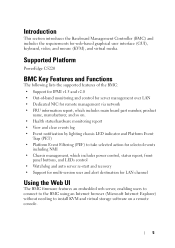
... the BMC using an Internet browser (Microsoft Internet Explorer) without needing to install KVM and virtual storage software on . • Health status/hardware monitoring report • View and clear events log • Event notification by lighting chassis LED indicator and Platform Event Trap (PET) • Platform Event Filtering (PEF) to take selected action for selected events including NMI • Chassis management, which includes power control, status report, front panel buttons, and LEDs control • Watchdog and auto server re-start and recovery • Support...
... the BMC using an Internet browser (Microsoft Internet Explorer) without needing to install KVM and virtual storage software on . • Health status/hardware monitoring report • View and clear events log • Event notification by lighting chassis LED indicator and Platform Event Trap (PET) • Platform Event Filtering (PEF) to take selected action for selected events including NMI • Chassis management, which includes power control, status report, front panel buttons, and LEDs control • Watchdog and auto server re-start and recovery • Support...
Using the Baseboard Management Controller
Page 11
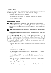
... and log back onto the BMC card before you want the BMC to auto reset after the update. 3 BMC will not check if the Firmware image belongs to C5220 platform when selecting Force Update. 4 Click the Upload Firmware button. 5 BMC will save it on your local system. You can perform any other user interface data files • Default configuration files Updating the BMC Firmware NOTE: Before beginning the firmware update, download the latest firmware version and save configure settings...
... and log back onto the BMC card before you want the BMC to auto reset after the update. 3 BMC will not check if the Firmware image belongs to C5220 platform when selecting Force Update. 4 Click the Upload Firmware button. 5 BMC will save it on your local system. You can perform any other user interface data files • Default configuration files Updating the BMC Firmware NOTE: Before beginning the firmware update, download the latest firmware version and save configure settings...


