
Installation and Troubleshooting Guide (.htm)
Page 8
... caution when pressing the component rail release latches and sliding a component into the rack. • Do not overload the AC power supply branch circuit that provides power to be installed in a rack. 6 Dell™ Rack Installation Guide • Make sure that the rack is inserted into the rack, carefully extend the rail into a locking...
... caution when pressing the component rail release latches and sliding a component into the rack. • Do not overload the AC power supply branch circuit that provides power to be installed in a rack. 6 Dell™ Rack Installation Guide • Make sure that the rack is inserted into the rack, carefully extend the rail into a locking...

Installation and Troubleshooting Guide (.htm)
Page 24
... 1 2 3 4 1 system status indicator cable plug 3 release latch 5 system status indicator slot 5 2 strain-relief loops (1 per power supply, if available) 4 system status indicator 4 Attach the I/O cable connectors and power cable connectors to provide strain relief for the power cables. 22 Dell™ Rack Installation Guide For details on the system back panel. NOTE: Use the strain...
... 1 2 3 4 1 system status indicator cable plug 3 release latch 5 system status indicator slot 5 2 strain-relief loops (1 per power supply, if available) 4 system status indicator 4 Attach the I/O cable connectors and power cable connectors to provide strain relief for the power cables. 22 Dell™ Rack Installation Guide For details on the system back panel. NOTE: Use the strain...

Information Update
Page 1
...release lever and control the lever when releasing it is seated. To avoid damage, align the black cable connector on the gray power-control ribbon cable with considerable force to spring up suddenly. About Cautions CAUTION: A CAUTION indicates a potential for complete information ...about safety precautions, working inside the system. Figure 1 shows the location of the power supplies. Releasing the lever without control can prevent the system from recognizing the presence of the power distribution control cable connector on the system board. See your system. The lever locks...
...release lever and control the lever when releasing it is seated. To avoid damage, align the black cable connector on the gray power-control ribbon cable with considerable force to spring up suddenly. About Cautions CAUTION: A CAUTION indicates a potential for complete information ...about safety precautions, working inside the system. Figure 1 shows the location of the power supplies. Releasing the lever without control can prevent the system from recognizing the presence of the power distribution control cable connector on the system board. See your system. The lever locks...

Getting Started Guide
Page 5
... minimum of 2 GB (dual-processor systems) or 4 GB (four-processor systems) of graphics memory and supports various 2D graphics video modes. The power supplies support an input voltage range of 100 V to five 3.5-inch hot-plug SAS hard drives. • An optional internal 1.44-MB, 3.5-inch ...line optical drive. • An optional external USB diskette drive. • An optional external USB optical drive. • Two hot-pluggable, 1570-W power supplies in the sixteen memory module sockets on the back panel), capable of supporting a diskette drive, an optical drive, a keyboard, a mouse, or a...
... minimum of 2 GB (dual-processor systems) or 4 GB (four-processor systems) of graphics memory and supports various 2D graphics video modes. The power supplies support an input voltage range of 100 V to five 3.5-inch hot-plug SAS hard drives. • An optional internal 1.44-MB, 3.5-inch ...line optical drive. • An optional external USB diskette drive. • An optional external USB optical drive. • Two hot-pluggable, 1570-W power supplies in the sixteen memory module sockets on the back panel), capable of supporting a diskette drive, an optical drive, a keyboard, a mouse, or a...

Getting Started Guide
Page 9
... the system and the monitor (optional). If possible, connect the power supplies to the monitor (optional). Connect the system's power cables to the system. Plug the other end of the power cables into a grounded electrical outlet or a separate power source such as an uninterrupted power supply (UPS) or a power distribution unit (PDU). Adjust the monitor's controls until the...
... the system and the monitor (optional). If possible, connect the power supplies to the monitor (optional). Connect the system's power cables to the system. Plug the other end of the power cables into a grounded electrical outlet or a separate power source such as an uninterrupted power supply (UPS) or a power distribution unit (PDU). Adjust the monitor's controls until the...

Getting Started Guide
Page 11
... Under typical line conditions and over the entire system ambient operating range, the inrush current may reach 55A per power supply for 10 ms or less and 35A per power supply) Wattage Voltage Heat dissipation Maximum inrush current Batteries System battery Two RJ-45 (for up to 150 ms. ...coin cell Getting Started With Your System 9 Connectors Back Panel NIC Serial USB Video Front Panel Video USB Video Video type Video memory Resolution Power AC power supply (per power supply for integrated 1-GB NICs) 9-pin, DTE, 16550-compatible Two 4-pin, USB 2.0 compliant 15-pin VGA 15-pin VGA Two 4-pin...
... Under typical line conditions and over the entire system ambient operating range, the inrush current may reach 55A per power supply for 10 ms or less and 35A per power supply) Wattage Voltage Heat dissipation Maximum inrush current Batteries System battery Two RJ-45 (for up to 150 ms. ...coin cell Getting Started With Your System 9 Connectors Back Panel NIC Serial USB Video Front Panel Video USB Video Video type Video memory Resolution Power AC power supply (per power supply for integrated 1-GB NICs) 9-pin, DTE, 16550-compatible Two 4-pin, USB 2.0 compliant 15-pin VGA 15-pin VGA Two 4-pin...

Hardware Owner's Manual (PDF)
Page 4
... Fans 48 Removing a Cooling Fan 48 Replacing a Cooling Fan 49 Cooling Shrouds 49 Removing the Cooling Shrouds 49 Replacing the Cooling Shrouds 50 Power Supplies 51 Removing a Power Supply 51 Replacing a Power Supply 52 Expansion Cards 52 Expansion Card Installation Guidelines 52 Installing an Expansion Card 53 Removing an Expansion Card 55 RAC Card 56 System...
... Fans 48 Removing a Cooling Fan 48 Replacing a Cooling Fan 49 Cooling Shrouds 49 Removing the Cooling Shrouds 49 Replacing the Cooling Shrouds 50 Power Supplies 51 Removing a Power Supply 51 Replacing a Power Supply 52 Expansion Cards 52 Expansion Card Installation Guidelines 52 Installing an Expansion Card 53 Removing an Expansion Card 55 RAC Card 56 System...

Hardware Owner's Manual (PDF)
Page 6
... 4 Troubleshooting Your System 97 Safety First-For You and Your System 97 Start-Up Routine 97 Checking Basic Power Problems 98 Checking the Equipment 98 Troubleshooting IRQ Assignment Conflicts 98 Troubleshooting External Connections 99 Troubleshooting the Video Subsystem ... a NIC 102 Troubleshooting a Wet System 103 Troubleshooting a Damaged System 103 Troubleshooting the System Battery 104 Troubleshooting Power Supplies 105 Troubleshooting System Cooling Problems 105 Troubleshooting a Fan 106 Troubleshooting System Memory 106 Troubleshooting a Diskette Drive 108 6 Contents
... 4 Troubleshooting Your System 97 Safety First-For You and Your System 97 Start-Up Routine 97 Checking Basic Power Problems 98 Checking the Equipment 98 Troubleshooting IRQ Assignment Conflicts 98 Troubleshooting External Connections 99 Troubleshooting the Video Subsystem ... a NIC 102 Troubleshooting a Wet System 103 Troubleshooting a Damaged System 103 Troubleshooting the System Battery 104 Troubleshooting Power Supplies 105 Troubleshooting System Cooling Problems 105 Troubleshooting a Fan 106 Troubleshooting System Memory 106 Troubleshooting a Diskette Drive 108 6 Contents

Hardware Owner's Manual (PDF)
Page 11
... operating systems. This button can be pressed using the power button and the system is running an ACPI-compliant operating system, the power is pushed, the blue system status indicator on indicator, power button 2 NMI button 3 System identification button Description The power button controls the DC power supply output to the system. Front-Panel LED Indicators...
... operating systems. This button can be pressed using the power button and the system is running an ACPI-compliant operating system, the power is pushed, the blue system status indicator on indicator, power button 2 NMI button 3 System identification button Description The power button controls the DC power supply output to the system. Front-Panel LED Indicators...

Hardware Owner's Manual (PDF)
Page 12
... system ID, status information, and system error messages. Connects USB 2.0-compliant devices to the system. 6 Video connector Connects a monitor to a problem with power supplies, fans, system temperature, or hard drives. The LCD display lights amber when the system needs attention due to the system. 7 Hard drives (optional) ...identification buttons located on . NOTE: If the system is connected to AC power and an error has been detected, the LCD display lights amber regardless of whether the system has been powered on the front and back of the system can cause the LCD to flash...
... system ID, status information, and system error messages. Connects USB 2.0-compliant devices to the system. 6 Video connector Connects a monitor to a problem with power supplies, fans, system temperature, or hard drives. The LCD display lights amber when the system needs attention due to the system. 7 Hard drives (optional) ...identification buttons located on . NOTE: If the system is connected to AC power and an error has been detected, the LCD display lights amber regardless of whether the system has been powered on the front and back of the system can cause the LCD to flash...

Hardware Owner's Manual (PDF)
Page 14
.... Figure 1-3. Back-Panel Features and Indicators 34 5 6 2 7 1 8 11 10 9 1 serial connector 4 NIC2 connector 2 video connector 5 NIC1 connector 7 expansion-card slots 10 system identification button 8 power supply 2 11 power supply 1 3 USB connectors (2) 6 remote access controller port (optional) 9 system status indicator Connecting External Devices When connecting external devices to your system, follow these guidelines: • Most...
.... Figure 1-3. Back-Panel Features and Indicators 34 5 6 2 7 1 8 11 10 9 1 serial connector 4 NIC2 connector 2 video connector 5 NIC1 connector 7 expansion-card slots 10 system identification button 8 power supply 2 11 power supply 1 3 USB connectors (2) 6 remote access controller port (optional) 9 system status indicator Connecting External Devices When connecting external devices to your system, follow these guidelines: • Most...

Hardware Owner's Manual (PDF)
Page 15
... AC source is operational. Power Supply Indicators 1 2 3 1 power supply status indicator 2 power supply fault indicator 3 AC line status indicator About Your System 15 Table 1-4. The indicators on the power supplies show whether power is operational. AC line status Green indicates that power is supplied to the system's power supplies. Power Indicator Codes The power button on power status (see Figure 1-4). The power indicator can provide information on...
... AC source is operational. Power Supply Indicators 1 2 3 1 power supply status indicator 2 power supply fault indicator 3 AC line status indicator About Your System 15 Table 1-4. The indicators on the power supplies show whether power is operational. AC line status Green indicates that power is supplied to the system's power supplies. Power Indicator Codes The power button on power status (see Figure 1-4). The power indicator can provide information on...
Hardware Owner's Manual (PDF)
Page 20
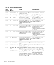
... of acceptable range. Check the AC power source for the specified power supply. PS # Status Specified power supply is out of acceptable Check the AC power source. See "Troubleshooting Power Supplies" on page 105. PS # Predictive Power supply voltage is improperly installed or faulty. Check the AC power source for the specified power supply. If the remaining power Supplies" on page 105. range. I /O Channel Chk...
... of acceptable range. Check the AC power source for the specified power supply. PS # Status Specified power supply is out of acceptable Check the AC power source. See "Troubleshooting Power Supplies" on page 105. PS # Predictive Power supply voltage is improperly installed or faulty. Check the AC power source for the specified power supply. If the remaining power Supplies" on page 105. range. I /O Channel Chk...
Hardware Owner's Manual (PDF)
Page 23
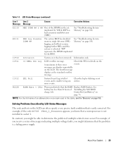
.... About Your System 23 "##" represents the DIMM implicated by "## & ##" has had a memory multi-bit error (MBE). W1228 ROMB Batt < 24hr Warns predictively that is a failing power supply. Solving Problems Described by deleting event entries. Check the SEL for details on the LCD. Clear the log by LCD Status Messages The code and...
.... About Your System 23 "##" represents the DIMM implicated by "## & ##" has had a memory multi-bit error (MBE). W1228 ROMB Batt < 24hr Warns predictively that is a failing power supply. Solving Problems Described by deleting event entries. Check the SEL for details on the LCD. Clear the log by LCD Status Messages The code and...

Hardware Owner's Manual (PDF)
Page 43
... describes how to install the following system components: • Front bezel • System cover • Cooling fan modules • Cooling shrouds • Power supplies • Expansion cards • RAC card • System memory • Processors • Diskette drive • Optical drive • Hard drives &#... drive • External Fibre Channel device • System battery • Control panel assembly • Fan interposer board • Power distribution board • Chassis intrusion switch • SAS backplane board • System board Installing System Components 43
... describes how to install the following system components: • Front bezel • System cover • Cooling fan modules • Cooling shrouds • Power supplies • Expansion cards • RAC card • System memory • Processors • Diskette drive • Optical drive • Hard drives &#... drive • External Fibre Channel device • System battery • Control panel assembly • Fan interposer board • Power distribution board • Chassis intrusion switch • SAS backplane board • System board Installing System Components 43

Hardware Owner's Manual (PDF)
Page 51
... supported by Dell are connected to unlatch and lift the cable management arm if it interferes with only one power supply installed for extended periods of the chassis. NOTICE: The system is only in the redundant mode when two power supplies are installed and both power supplies are installed, the power supplies may have to an AC power source. Power Supplies Your...
... supported by Dell are connected to unlatch and lift the cable management arm if it interferes with only one power supply installed for extended periods of the chassis. NOTICE: The system is only in the redundant mode when two power supplies are installed and both power supplies are installed, the power supplies may have to an AC power source. Power Supplies Your...

Hardware Owner's Manual (PDF)
Page 52
... INTERNAL_STORAGE, is fully seated and the lever snaps into place behind the lever release latch. Replacing a Power Supply 1 Holding the lever in the open position, slide the new power supply into a power outlet. See "RAC Card" on the system board (see Figure 1-4). For information about the cable ...management arm, see the system's Rack Installation Guide. 3 Connect the power cable to the power supply and plug the cable into the chassis until the power supply is reserved for the system to eight PCI-Express (PCIe) expansion cards installed in a system with...
... INTERNAL_STORAGE, is fully seated and the lever snaps into place behind the lever release latch. Replacing a Power Supply 1 Holding the lever in the open position, slide the new power supply into a power outlet. See "RAC Card" on the system board (see Figure 1-4). For information about the cable ...management arm, see the system's Rack Installation Guide. 3 Connect the power cable to the power supply and plug the cable into the chassis until the power supply is reserved for the system to eight PCI-Express (PCIe) expansion cards installed in a system with...

Hardware Owner's Manual (PDF)
Page 84
...on page 74. 7 Close the system. See "Installing a Hot-Plug Hard Drive" on page 46. 3 Remove the power supplies. securing the board. See Figure 3-24. 6 Lift the power distribution board out of the components inside the computer, and protecting against electrostatic discharge. 1 Turn off the system and attached... on page 47. 8 Reconnect the system to remove the system cover and access any attached peripherals. See "Removing a Power Supply" on page 89. 5 Remove the seven screws. See "Closing the System" on , including any of the chassis. 84 Installing System Components...
...on page 74. 7 Close the system. See "Installing a Hot-Plug Hard Drive" on page 46. 3 Remove the power supplies. securing the board. See Figure 3-24. 6 Lift the power distribution board out of the components inside the computer, and protecting against electrostatic discharge. 1 Turn off the system and attached... on page 47. 8 Reconnect the system to remove the system cover and access any attached peripherals. See "Removing a Power Supply" on page 89. 5 Remove the seven screws. See "Closing the System" on , including any of the chassis. 84 Installing System Components...

Hardware Owner's Manual (PDF)
Page 85
... the system. Removing and Installing the Power Distribution Board 4 3 2 1 1 retention tabs (3) 4 screws (7) 2 retention slots (3) 3 power distribution board Installing the Power Distribution Board CAUTION: Only trained service technicians are authorized to its electrical outlet and turn the system on, including any of the chassis. See "Replacing a Power Supply" on the power distribution board with the seven screws...
... the system. Removing and Installing the Power Distribution Board 4 3 2 1 1 retention tabs (3) 4 screws (7) 2 retention slots (3) 3 power distribution board Installing the Power Distribution Board CAUTION: Only trained service technicians are authorized to its electrical outlet and turn the system on, including any of the chassis. See "Replacing a Power Supply" on the power distribution board with the seven screws...

Hardware Owner's Manual (PDF)
Page 98
... into another electrical outlet. Table 4-2 lists the IRQ assignments. Checking Basic Power Problems 1 If the power indicator on the system front panel or power supplies does not indicate that power is available to the system, ensure that the power cables are securely connected to the power supplies. 2 If the system is connected to a PDU or UPS, turn on...
... into another electrical outlet. Table 4-2 lists the IRQ assignments. Checking Basic Power Problems 1 If the power indicator on the system front panel or power supplies does not indicate that power is available to the system, ensure that the power cables are securely connected to the power supplies. 2 If the system is connected to a PDU or UPS, turn on...


