
Installation and Troubleshooting Guide (.htm)
Page 8
...Use caution when pressing the component rail release latches and sliding a component into the rack. • Do not overload the AC power supply branch circuit that provides power to components in the rack. • Do not step on or stand on any system/component when servicing other systems/components in...slide rails can be installed by trained service technicians in a rack. Use only the rack kit for each system installed in a rack. 6 Dell™ Rack Installation Guide NOTICE: The RapidRails rack kit is provided to the rack. The total rack load should not exceed 80 percent of...
...Use caution when pressing the component rail release latches and sliding a component into the rack. • Do not overload the AC power supply branch circuit that provides power to components in the rack. • Do not step on or stand on any system/component when servicing other systems/components in...slide rails can be installed by trained service technicians in a rack. Use only the rack kit for each system installed in a rack. 6 Dell™ Rack Installation Guide NOTICE: The RapidRails rack kit is provided to the rack. The total rack load should not exceed 80 percent of...

Installation and Troubleshooting Guide (.htm)
Page 24
...5 system status indicator slot 5 2 strain-relief loops (1 per power supply, if available) 4 system status indicator 4 Attach the I/O cable connectors and power cable connectors to provide strain relief for the power cables. 22 Dell™ Rack Installation Guide NOTE: Use the strain-relief loops (...if available) on the back of the power supplies to their respective connectors on cable ...
...5 system status indicator slot 5 2 strain-relief loops (1 per power supply, if available) 4 system status indicator 4 Attach the I/O cable connectors and power cable connectors to provide strain relief for the power cables. 22 Dell™ Rack Installation Guide NOTE: Use the strain-relief loops (...if available) on the back of the power supplies to their respective connectors on cable ...

Information Update
Page 1
... not spring up suddenly and forcefully. Update to Processor Installation When removing or installing the processor, be careful when connecting the power distribution cable between the two boards that you do not bend or damage the pins on the socket release lever and control ...prevent the system from recognizing the presence of the components inside the computer, and protecting against electrostatic discharge. For information on replacing the power distribution board or system board, see "Installing System Components" in your finger or thumb firmly on the system board connector. Bent ...
... not spring up suddenly and forcefully. Update to Processor Installation When removing or installing the processor, be careful when connecting the power distribution cable between the two boards that you do not bend or damage the pins on the socket release lever and control ...prevent the system from recognizing the presence of the components inside the computer, and protecting against electrostatic discharge. For information on replacing the power distribution board or system board, see "Installing System Components" in your finger or thumb firmly on the system board connector. Bent ...

Information Update
Page 2
Figure 1. Power Distribution Control Cable Connector on the System Board 1 1 PWR_3.3Stby_Cntrl Power distribution board control cable connector
Figure 1. Power Distribution Control Cable Connector on the System Board 1 1 PWR_3.3Stby_Cntrl Power distribution board control cable connector

Getting Started Guide
Page 5
... external USB diskette drive. • An optional external USB optical drive. • Two hot-pluggable, 1570-W power supplies in the sixteen memory module sockets on an integrated ATI RN50 33-MHz PCI video controller. The power supplies support an input voltage range of graphics memory and supports various 2D graphics video modes...
... external USB diskette drive. • An optional external USB optical drive. • Two hot-pluggable, 1570-W power supplies in the sixteen memory module sockets on an integrated ATI RN50 33-MHz PCI video controller. The power supplies support an input voltage range of graphics memory and supports various 2D graphics video modes...

Getting Started Guide
Page 9
... system bezel, install it after turning on the system and the monitor (optional). Turning on the System and Monitor Press the power button on the system. If possible, connect the power supplies to the monitor (optional). Getting Started With Your System 7 Adjust the monitor's controls until the displayed image is satisfactory. Connect...
... system bezel, install it after turning on the system and the monitor (optional). Turning on the System and Monitor Press the power button on the system. If possible, connect the power supplies to the monitor (optional). Getting Started With Your System 7 Adjust the monitor's controls until the displayed image is satisfactory. Connect...

Getting Started Guide
Page 11
Connectors Back Panel NIC Serial USB Video Front Panel Video USB Video Video type Video memory Resolution Power AC power supply (per power supply for integrated 1-GB NICs) 9-pin, DTE, 16550-compatible Two 4-pin, USB 2.0 compliant 15-pin VGA 15-pin VGA Two 4-pin, USB 2.0 compliant ATI RN50 .../hr (maximum) Under typical line conditions and over the entire system ambient operating range, the inrush current may reach 55A per power supply for 10 ms or less and 35A per power supply) Wattage Voltage Heat dissipation Maximum inrush current Batteries System battery Two RJ-45 (for up to 150 ms. CR...
Connectors Back Panel NIC Serial USB Video Front Panel Video USB Video Video type Video memory Resolution Power AC power supply (per power supply for integrated 1-GB NICs) 9-pin, DTE, 16550-compatible Two 4-pin, USB 2.0 compliant 15-pin VGA 15-pin VGA Two 4-pin, USB 2.0 compliant ATI RN50 .../hr (maximum) Under typical line conditions and over the entire system ambient operating range, the inrush current may reach 55A per power supply for 10 ms or less and 35A per power supply) Wattage Voltage Heat dissipation Maximum inrush current Batteries System battery Two RJ-45 (for up to 150 ms. CR...

Hardware Owner's Manual (PDF)
Page 3
... Features During Startup 10 Front-Panel Features and Indicators 11 Hard-Drive Indicator Codes 13 Back-Panel Features and Indicators 14 Connecting External Devices 14 Power Indicator Codes 15 NIC Indicator Codes 16 LCD Status Messages 16 Solving Problems Described by LCD Status Messages 23 Removing LCD Status Messages 24 System...
... Features During Startup 10 Front-Panel Features and Indicators 11 Hard-Drive Indicator Codes 13 Back-Panel Features and Indicators 14 Connecting External Devices 14 Power Indicator Codes 15 NIC Indicator Codes 16 LCD Status Messages 16 Solving Problems Described by LCD Status Messages 23 Removing LCD Status Messages 24 System...

Hardware Owner's Manual (PDF)
Page 4
... 48 Removing a Cooling Fan 48 Replacing a Cooling Fan 49 Cooling Shrouds 49 Removing the Cooling Shrouds 49 Replacing the Cooling Shrouds 50 Power Supplies 51 Removing a Power Supply 51 Replacing a Power Supply 52 Expansion Cards 52 Expansion Card Installation Guidelines 52 Installing an Expansion Card 53 Removing an Expansion Card 55 RAC Card...
... 48 Removing a Cooling Fan 48 Replacing a Cooling Fan 49 Cooling Shrouds 49 Removing the Cooling Shrouds 49 Replacing the Cooling Shrouds 50 Power Supplies 51 Removing a Power Supply 51 Replacing a Power Supply 52 Expansion Cards 52 Expansion Card Installation Guidelines 52 Installing an Expansion Card 53 Removing an Expansion Card 55 RAC Card...

Hardware Owner's Manual (PDF)
Page 5
... Control Panel 80 Installing the Control Panel 81 Fan Interposer Board (Service-Only Procedure 82 Removing a Fan Interposer Board 82 Installing a Fan Interposer Board 83 Power Distribution Board (Service-Only Procedure 84 Removing the...
... Control Panel 80 Installing the Control Panel 81 Fan Interposer Board (Service-Only Procedure 82 Removing a Fan Interposer Board 82 Installing a Fan Interposer Board 83 Power Distribution Board (Service-Only Procedure 84 Removing the...

Hardware Owner's Manual (PDF)
Page 6
...93 4 Troubleshooting Your System 97 Safety First-For You and Your System 97 Start-Up Routine 97 Checking Basic Power Problems 98 Checking the Equipment 98 Troubleshooting IRQ Assignment Conflicts 98 Troubleshooting External Connections 99 Troubleshooting the Video Subsystem ...a NIC 102 Troubleshooting a Wet System 103 Troubleshooting a Damaged System 103 Troubleshooting the System Battery 104 Troubleshooting Power Supplies 105 Troubleshooting System Cooling Problems 105 Troubleshooting a Fan 106 Troubleshooting System Memory 106 Troubleshooting a Diskette Drive 108 6 Contents
...93 4 Troubleshooting Your System 97 Safety First-For You and Your System 97 Start-Up Routine 97 Checking Basic Power Problems 98 Checking the Equipment 98 Troubleshooting IRQ Assignment Conflicts 98 Troubleshooting External Connections 99 Troubleshooting the Video Subsystem ...a NIC 102 Troubleshooting a Wet System 103 Troubleshooting a Damaged System 103 Troubleshooting the System Battery 104 Troubleshooting Power Supplies 105 Troubleshooting System Cooling Problems 105 Troubleshooting a Fan 106 Troubleshooting System Memory 106 Troubleshooting a Diskette Drive 108 6 Contents

Hardware Owner's Manual (PDF)
Page 11
... shows the controls, indicators, and connectors located behind the optional rack bezel on indicator, power button 2 NMI button 3 System identification button Description The power button controls the DC power supply output to the system. Use this button only if directed to locate a particular system... within a rack. If the system is not running an ACPI-compliant operating system, the system performs a graceful shutdown before the power is pressed. Front-Panel Features and Indicators 2 34 5 6 7 1 8 Table 1-2. When one of the buttons is pushed again. ...
... shows the controls, indicators, and connectors located behind the optional rack bezel on indicator, power button 2 NMI button 3 System identification button Description The power button controls the DC power supply output to the system. Use this button only if directed to locate a particular system... within a rack. If the system is not running an ACPI-compliant operating system, the system performs a graceful shutdown before the power is pressed. Front-Panel Features and Indicators 2 34 5 6 7 1 8 Table 1-2. When one of the buttons is pushed again. ...

Hardware Owner's Manual (PDF)
Page 12
... and diskette drive (optional) NOTE: DVD devices are data only. Connects USB 2.0-compliant devices to the system. 6 Video connector Connects a monitor to AC power and an error has been detected, the LCD display lights amber regardless of the system can cause the LCD to flash blue to a problem with... power supplies, fans, system temperature, or hard drives. Optional slimline optical drive and diskette drive 12 About Your System The LCD display lights during...
... and diskette drive (optional) NOTE: DVD devices are data only. Connects USB 2.0-compliant devices to the system. 6 Video connector Connects a monitor to AC power and an error has been detected, the LCD display lights amber regardless of the system can cause the LCD to flash blue to a problem with... power supplies, fans, system temperature, or hard drives. Optional slimline optical drive and diskette drive 12 About Your System The LCD display lights during...

Hardware Owner's Manual (PDF)
Page 13
... is installed, the "drive being prepared for insertion or removal" pattern. Table 1-3. Blinks green, amber, and off until all hard drives are initialized after system power is selected for removal, the "drive being prepared for operation" pattern appears, followed by the "drive ready for removal" pattern appears, followed by the "drive...
... is installed, the "drive being prepared for insertion or removal" pattern. Table 1-3. Blinks green, amber, and off until all hard drives are initialized after system power is selected for removal, the "drive being prepared for operation" pattern appears, followed by the "drive ready for removal" pattern appears, followed by the "drive...

Hardware Owner's Manual (PDF)
Page 14
... panel. Back-Panel Features and Indicators 34 5 6 2 7 1 8 11 10 9 1 serial connector 4 NIC2 connector 2 video connector 5 NIC1 connector 7 expansion-card slots 10 system identification button 8 power supply 2 11 power supply 1 3 USB connectors (2) 6 remote access controller port (optional) 9 system status indicator Connecting External Devices When connecting external devices to your system is turned off...
... panel. Back-Panel Features and Indicators 34 5 6 2 7 1 8 11 10 9 1 serial connector 4 NIC2 connector 2 video connector 5 NIC1 connector 7 expansion-card slots 10 system identification button 8 power supply 2 11 power supply 1 3 USB connectors (2) 6 remote access controller port (optional) 9 system status indicator Connecting External Devices When connecting external devices to your system is turned off...

Hardware Owner's Manual (PDF)
Page 15
... system and the system is supplied to the system's power supplies. Power Supply Indicators Indicator Function Power supply status Green indicates that no power is operational. Power supply fault Amber indicates a problem with the power supply. Figure 1-4. Table 1-4 lists the power button indicator codes. Power Supply Indicators 1 2 3 1 power supply status indicator 2 power supply fault indicator 3 AC line status indicator About...
... system and the system is supplied to the system's power supplies. Power Supply Indicators Indicator Function Power supply status Green indicates that no power is operational. Power supply fault Amber indicates a problem with the power supply. Figure 1-4. Table 1-4 lists the power button indicator codes. Power Supply Indicators 1 2 3 1 power supply status indicator 2 power supply fault indicator 3 AC line status indicator About...

Hardware Owner's Manual (PDF)
Page 17
...VCORE voltage regulator has failed. Program" on page 127. the SAS backplane. See "SAS Backplane Board Connectors" on page 31. • The power is for information defined by the user in the System Setup program. See bad, or unable to recharge due to or bad. failed. About... "Using the System Setup • The system is See "Troubleshooting System out of acceptable range. the SAS backplane. Ambient system temperature is powered on page 129. Specified voltage regulator has See "Getting Help" on page 105. RAID battery is unseated, missing, Check the cable connection ...
...VCORE voltage regulator has failed. Program" on page 127. the SAS backplane. See "SAS Backplane Board Connectors" on page 31. • The power is for information defined by the user in the System Setup program. See bad, or unable to recharge due to or bad. failed. About... "Using the System Setup • The system is See "Troubleshooting System out of acceptable range. the SAS backplane. Ambient system temperature is powered on page 129. Specified voltage regulator has See "Getting Help" on page 105. RAID battery is unseated, missing, Check the cable connection ...

Hardware Owner's Manual (PDF)
Page 18
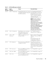
...microprocessor is See "Troubleshooting System out of specified cooling fan is reporting a system error. See "Troubleshooting System Cooling Problems" on support.dell.com for the most current system information. See your system's Information Update Tech Sheet located on page 105. LCD Status Messages (...continued) Line 1 Message E122B E122C E122D E122E E1310 E1313 Line 2 Message 0.9V Over Voltage CPU Power Fault CPU # VDDIO CPU # VDDA RPM Fan ## Fan Redundancy Causes Corrective Actions 0.9 V regulator voltage has exceeded the allowable voltage ...
...microprocessor is See "Troubleshooting System out of specified cooling fan is reporting a system error. See "Troubleshooting System Cooling Problems" on support.dell.com for the most current system information. See your system's Information Update Tech Sheet located on page 105. LCD Status Messages (...continued) Line 1 Message E122B E122C E122D E122E E1310 E1313 Line 2 Message 0.9V Over Voltage CPU Power Fault CPU # VDDIO CPU # VDDA RPM Fan ## Fan Redundancy Causes Corrective Actions 0.9 V regulator voltage has exceeded the allowable voltage ...
Hardware Owner's Manual (PDF)
Page 19
...The LCD continues to display this message until the system's power cord is disconnected and reconnected to the type described in the Microprocessor Technical Specifications outlined in a configuration unsupported by Dell. VRM for information about these utilities. See "Processor VRMs...Specified microprocessor is missing or faulty. has halted operation. See "Troubleshooting the Microprocessors" on page 66. See the Dell OpenManage Baseboard Management Controller User's Guide for specified processor is out of See "Troubleshooting System acceptable temperature range and ...
...The LCD continues to display this message until the system's power cord is disconnected and reconnected to the type described in the Microprocessor Technical Specifications outlined in a configuration unsupported by Dell. VRM for information about these utilities. See "Processor VRMs...Specified microprocessor is missing or faulty. has halted operation. See "Troubleshooting the Microprocessors" on page 66. See the Dell OpenManage Baseboard Management Controller User's Guide for specified processor is out of See "Troubleshooting System acceptable temperature range and ...
Hardware Owner's Manual (PDF)
Page 20
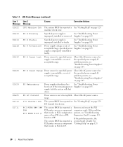
... and reseat the PCI expansion cards. See "Getting Help" on page 129. supply is See "Troubleshooting Power improperly installed or removed. If the remaining power Supplies" on page 105. If the problem persists, the system board is improperly installed or faulty. Table... 1-7. PS # Status Specified power supply is faulty. range. PS # Predictive Power supply voltage is unavailable, or out of See "Troubleshooting Power acceptable range; Check the AC power source for the specified power supply. See "Troubleshooting Power Supplies" on page 105. The system BIOS...
... and reseat the PCI expansion cards. See "Getting Help" on page 129. supply is See "Troubleshooting Power improperly installed or removed. If the remaining power Supplies" on page 105. If the problem persists, the system board is improperly installed or faulty. Table... 1-7. PS # Status Specified power supply is faulty. range. PS # Predictive Power supply voltage is unavailable, or out of See "Troubleshooting Power acceptable range; Check the AC power source for the specified power supply. See "Troubleshooting Power Supplies" on page 105. The system BIOS...


