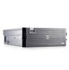
System Memory Information Update — 8 GB Memory Modules
Page 1
... disclaims any manner whatsoever without notice. © 2007 Dell Inc. If quad-ranked 8 GB modules are trademarks of the processor memory controller, the system memory will be used in this text: Dell and the DELL logo are combined with other than 667 MHz. A message notifying you that a non-optimal configuration is strictly forbidden. All rights reserved.
... disclaims any manner whatsoever without notice. © 2007 Dell Inc. If quad-ranked 8 GB modules are trademarks of the processor memory controller, the system memory will be used in this text: Dell and the DELL logo are combined with other than 667 MHz. A message notifying you that a non-optimal configuration is strictly forbidden. All rights reserved.

Getting Started Guide
Page 5
... USB optical drive. • Two hot-pluggable, 1570-W power supplies in an 1 + 1 redundant configuration. The video subsystem includes 16 MB of 667-MHz registered DDR-II memory modules. The system board includes the following features: • Two x8 lane-width PCI-Express (PCIe)..., a mouse, or a USB flash drive. • Systems management circuitry that monitors operation of 512-MB, 1-GB, 2-GB, or 4-GB memory modules in conjunction with the systems management software. • Standard Baseboard Management Controller (BMC) with 65,536 colors. (When the optional RAC is installed...
... USB optical drive. • Two hot-pluggable, 1570-W power supplies in an 1 + 1 redundant configuration. The video subsystem includes 16 MB of 667-MHz registered DDR-II memory modules. The system board includes the following features: • Two x8 lane-width PCI-Express (PCIe)..., a mouse, or a USB flash drive. • Systems management circuitry that monitors operation of 512-MB, 1-GB, 2-GB, or 4-GB memory modules in conjunction with the systems management software. • Standard Baseboard Management Controller (BMC) with 65,536 colors. (When the optional RAC is installed...

Hardware Owner's Manual (PDF)
Page 4
... and Setup Password Features 38 Using the System Password 38 Using the Setup Password 40 Disabling a Forgotten Password 41 Baseboard Management Controller Configuration 41 Entering the BMC Setup Module 42 BMC Setup Module Options 42 3 Installing System Components 43 Recommended Tools 44 Inside the System ...52 Expansion Cards 52 Expansion Card Installation Guidelines 52 Installing an Expansion Card 53 Removing an Expansion Card 55 RAC Card 56 System Memory 57 General Memory Module Installation Guidelines 58 Installing Memory Modules 60 Removing Memory Modules 61 4 Contents
... and Setup Password Features 38 Using the System Password 38 Using the Setup Password 40 Disabling a Forgotten Password 41 Baseboard Management Controller Configuration 41 Entering the BMC Setup Module 42 BMC Setup Module Options 42 3 Installing System Components 43 Recommended Tools 44 Inside the System ...52 Expansion Cards 52 Expansion Card Installation Guidelines 52 Installing an Expansion Card 53 Removing an Expansion Card 55 RAC Card 56 System Memory 57 General Memory Module Installation Guidelines 58 Installing Memory Modules 60 Removing Memory Modules 61 4 Contents

Hardware Owner's Manual (PDF)
Page 21
...RAC Card" on page 106. Error detected during memory configuration. See "Troubleshooting System Memory" on page 56. Memory subsystem failure. No Memory No memory is missing or Reconnect the cable. See "System Memory" on page 110. Unusable Memory Memory is configured, but is faulty. If the problem that there... ##, device ##, Expansion Cards" on page 113. If the problem persists, the system board is not configurable. See "Getting Help" on page 129. Install memory modules. About Your System 21 See "Getting Help" on page 129. HDD ## Fault Specified hard drive...
...RAC Card" on page 106. Error detected during memory configuration. See "Troubleshooting System Memory" on page 56. Memory subsystem failure. No Memory No memory is missing or Reconnect the cable. See "System Memory" on page 110. Unusable Memory Memory is configured, but is faulty. If the problem that there... ##, device ##, Expansion Cards" on page 113. If the problem persists, the system board is not configurable. See "Getting Help" on page 129. Install memory modules. About Your System 21 See "Getting Help" on page 129. HDD ## Fault Specified hard drive...
Hardware Owner's Manual (PDF)
Page 22
... on page 129. See "Getting Help" on page 129. (SMI) initialization failure. DRAC Config Dell remote access controller Check screen for specific error Memory population order messages. If problem persists, see "Getting Help" on page 129. LCD Status Messages...management interrupt See "Getting Help" on page 129. See "Troubleshooting System Memory" on page 56. See "RAC Card" on page 106. CPU Config CPU configuration failure. Memory Population Incorrect memory configuration. See "Troubleshooting incorrect. Int Controller Interrupt controller failure. See "Getting...
... on page 129. See "Getting Help" on page 129. (SMI) initialization failure. DRAC Config Dell remote access controller Check screen for specific error Memory population order messages. If problem persists, see "Getting Help" on page 129. LCD Status Messages...management interrupt See "Getting Help" on page 129. See "Troubleshooting System Memory" on page 56. See "RAC Card" on page 106. CPU Config CPU configuration failure. Memory Population Incorrect memory configuration. See "Troubleshooting incorrect. Int Controller Interrupt controller failure. See "Getting...

Hardware Owner's Manual (PDF)
Page 24
...with the system. CAUTION: Only trained service technicians are installed in a configuration that sensor returns to the same display entry. Table 1-8. Node Interleaving The memory configuration does not disabled! The configuration does not system will reappear under the following conditions: • The ...8226; A failure is recorded from the display: • Clear the SEL - If the problem persists, see "Troubleshooting System Memory" on page 58. Any of the components inside the computer, and protecting against electrostatic discharge. Table 1-8 lists the system ...
...with the system. CAUTION: Only trained service technicians are installed in a configuration that sensor returns to the same display entry. Table 1-8. Node Interleaving The memory configuration does not disabled! The configuration does not system will reappear under the following conditions: • The ...8226; A failure is recorded from the display: • Clear the SEL - If the problem persists, see "Troubleshooting System Memory" on page 58. Any of the components inside the computer, and protecting against electrostatic discharge. Table 1-8 lists the system ...

Hardware Owner's Manual (PDF)
Page 25
...) Message Causes Corrective Actions Attempting to process Remote Configuration request. Retry the BIOS update. persists, see "Troubleshooting a Diskette Drive" on page 108. Faulty or improperly seated memory See "Troubleshooting System Memory" module(s). been detected and is installed. Remove the...faulty DIMM as soon as possible. Diskette drive n seek failure Incorrect configuration settings in diskette drive. Remote BIOS update attempt failed. on page 97. Replace the diskette. Error: Memory failure detected. Fatal error caused a system reset: Please check the...
...) Message Causes Corrective Actions Attempting to process Remote Configuration request. Retry the BIOS update. persists, see "Troubleshooting a Diskette Drive" on page 108. Faulty or improperly seated memory See "Troubleshooting System Memory" module(s). been detected and is installed. Remove the...faulty DIMM as soon as possible. Diskette drive n seek failure Incorrect configuration settings in diskette drive. Remote BIOS update attempt failed. on page 97. Replace the diskette. Error: Memory failure detected. Fatal error caused a system reset: Please check the...

Hardware Owner's Manual (PDF)
Page 26
... problem. The operating system is usually followed by keystroke. Faulty or improperly installed memory See "Troubleshooting System Memory" modules. System Messages (continued) Message Gate A20 failure General failure Invalid NVRAM configuration, Resource Re-allocated Keyboard Controller failure Manufacturing mode detected Memory address line failure at address, read value expecting value Causes Faulty keyboard controller...
... problem. The operating system is usually followed by keystroke. Faulty or improperly installed memory See "Troubleshooting System Memory" modules. System Messages (continued) Message Gate A20 failure General failure Invalid NVRAM configuration, Resource Re-allocated Keyboard Controller failure Manufacturing mode detected Memory address line failure at address, read value expecting value Causes Faulty keyboard controller...

Hardware Owner's Manual (PDF)
Page 28
... are card installed in the correct expansion slot. SAS port n hard disk drive SAS cables are securely connected to process Remote Configuration request. Shutdown failure Shutdown test failure. If memory has been added or removed, this message is installed in wrong expansion slot. See "Troubleshooting System... in your system. RAC cables not connected, or RAC Check that the RAC card is informative and can be faulty. Retry Remote Configuration. If memory has not been added or removed, check the SEL to determine if single-bit or multi-bit errors were detected and replace the ...
... are card installed in the correct expansion slot. SAS port n hard disk drive SAS cables are securely connected to process Remote Configuration request. Shutdown failure Shutdown test failure. If memory has been added or removed, this message is installed in wrong expansion slot. See "Troubleshooting System... in your system. RAC cables not connected, or RAC Check that the RAC card is informative and can be faulty. Retry Remote Configuration. If memory has not been added or removed, check the SEL to determine if single-bit or multi-bit errors were detected and replace the ...
Hardware Owner's Manual (PDF)
Page 29
..." on page 129. Utility partition not available The key was pressed during POST, but with your system. Warning! Invalid memory configuration. If the problem persists, see the system documentation on the technical support web site. No microcode update loaded for processor...utility partition on page 129. on page 104. Warning: The installed memory configuration is not supported by CPUn. Warning: One or more information on valid memory configurations, please see "Troubleshooting System Memory" on the boot hard drive. Ensure that came with reduced functionality....
..." on page 129. Utility partition not available The key was pressed during POST, but with your system. Warning! Invalid memory configuration. If the problem persists, see the system documentation on the technical support web site. No microcode update loaded for processor...utility partition on page 129. on page 104. Warning: The installed memory configuration is not supported by CPUn. Warning: One or more information on valid memory configurations, please see "Troubleshooting System Memory" on the boot hard drive. Ensure that came with reduced functionality....

Hardware Owner's Manual (PDF)
Page 31
... is normal for example, the time or date • Enable or disable integrated devices • Correct discrepancies between the installed hardware and configuration settings Entering the System Setup Program 1 Turn on or restart your system. 2 Press immediately after you add, change, or remove hardware...System Setup program by responding to send a message the first time you start your system and try again. NOTE: After installing a memory upgrade, it is booting, make a note of the message and suggestions for future reference. Record the information for correcting errors. Using ...
... is normal for example, the time or date • Enable or disable integrated devices • Correct discrepancies between the installed hardware and configuration settings Entering the System Setup Program 1 Turn on or restart your system. 2 Press immediately after you add, change, or remove hardware...System Setup program by responding to send a message the first time you start your system and try again. NOTE: After installing a memory upgrade, it is booting, make a note of the message and suggestions for future reference. Record the information for correcting errors. Using ...

Hardware Owner's Manual (PDF)
Page 33
Table 2-2. System Setup Program Options Option System Time System Date Memory Information CPU Information Description Resets the time on page 37. NOTE: The options for ... The System Setup program defaults are listed under their respective options, where applicable. See "Memory Information Screen" on the system's internal calendar. Displays information related to installed memory. Resets the date on page 35. Displays information related to microprocessors (speed, cache size,... Setup program change based on page 35. See "CPU Information Screen" on the system configuration.
Table 2-2. System Setup Program Options Option System Time System Date Memory Information CPU Information Description Resets the time on page 37. NOTE: The options for ... The System Setup program defaults are listed under their respective options, where applicable. See "Memory Information Screen" on the system's internal calendar. Displays information related to installed memory. Resets the date on page 35. Displays information related to microprocessors (speed, cache size,... Setup program change based on page 35. See "CPU Information Screen" on the system configuration.

Hardware Owner's Manual (PDF)
Page 35
... installed. If this field is enabled, memory interleaving is supported if a symmetric memory configuration is set to the operating system. Table 2-4. If any of video memory. Memory Information Screen Table 2-4 lists the descriptions for the information fields that appear on page 58. See "General Memory Module Installation Guidelines" on the Memory Information screen. Displays the model number...
... installed. If this field is enabled, memory interleaving is supported if a symmetric memory configuration is set to the operating system. Table 2-4. If any of video memory. Memory Information Screen Table 2-4 lists the descriptions for the information fields that appear on page 58. See "General Memory Module Installation Guidelines" on the Memory Information screen. Displays the model number...

Hardware Owner's Manual (PDF)
Page 57
... the Boot Sequence has changed to a maximum of 32 GB (two-processor configurations) or 64 GB (four-processor configurations) by installing 667-MHz registered DDR-II memory modules (DIMMs) in sets of the RAC card. Each processor has four memory channels, organized in sets of 512-MB, 1-GB, 2-GB, or 4-GB... can upgrade your Hardware Owner's Manual. 15 Exit the System Setup program and reboot the system. The sixteen memory sockets are located on configuring and using the RAC. Press to the storage controller card and feed the cables through the appropriate channels and keepers on page 50...
... the Boot Sequence has changed to a maximum of 32 GB (two-processor configurations) or 64 GB (four-processor configurations) by installing 667-MHz registered DDR-II memory modules (DIMMs) in sets of the RAC card. Each processor has four memory channels, organized in sets of 512-MB, 1-GB, 2-GB, or 4-GB... can upgrade your Hardware Owner's Manual. 15 Exit the System Setup program and reboot the system. The sixteen memory sockets are located on configuring and using the RAC. Press to the storage controller card and feed the cables through the appropriate channels and keepers on page 50...

Hardware Owner's Manual (PDF)
Page 58
...must be identical in a two-processor configuration (Table 3-2) or a four-processor configuration (Table 3-3). 58 Installing System Components Your system hardware supports Non-Uniform Memory Architecture (NUMA). Each processor has its own memory controller and local memory for reduced access times, but it... can either be the same size. General Memory Module Installation Guidelines To ensure optimal performance of your system, observe the following guidelines when configuring your system memory. • Memory modules must be installed in pairs, beginning with DIMM1 and DIMM2...
...must be identical in a two-processor configuration (Table 3-2) or a four-processor configuration (Table 3-3). 58 Installing System Components Your system hardware supports Non-Uniform Memory Architecture (NUMA). Each processor has its own memory controller and local memory for reduced access times, but it... can either be the same size. General Memory Module Installation Guidelines To ensure optimal performance of your system, observe the following guidelines when configuring your system memory. • Memory modules must be installed in pairs, beginning with DIMM1 and DIMM2...

Hardware Owner's Manual (PDF)
Page 59
Two-Processor Memory Configurations Total System Memory 2 GB 4 GB 4 GB 6 GB 8 GB 8 GB 16 GB 16 GB 24 GB 32 GB DIMM1 512 MB 512 MB 1 GB 1 GB 1 GB 2 GB 2 GB 4 GB 4 ... MB 512 MB 1 GB 2 GB 2 GB 4 GB DIMM8 512 MB 512 MB 1 GB 2 GB 2 GB 4 GB Table 3-3. Table 3-2. Four-Processor Memory Configurations Total CPU1 CPU2 CPU3 CPU4 System DIMM DIMM DIMM DIMM Memory 1 2 3 4 5 6 7 8 9 10 11 12 13 14 15 16 4GB 512 512 MB MB 512 512 MB MB 512 512 MB MB...
Two-Processor Memory Configurations Total System Memory 2 GB 4 GB 4 GB 6 GB 8 GB 8 GB 16 GB 16 GB 24 GB 32 GB DIMM1 512 MB 512 MB 1 GB 1 GB 1 GB 2 GB 2 GB 4 GB 4 ... MB 512 MB 1 GB 2 GB 2 GB 4 GB DIMM8 512 MB 512 MB 1 GB 2 GB 2 GB 4 GB Table 3-3. Table 3-2. Four-Processor Memory Configurations Total CPU1 CPU2 CPU3 CPU4 System DIMM DIMM DIMM DIMM Memory 1 2 3 4 5 6 7 8 9 10 11 12 13 14 15 16 4GB 512 512 MB MB 512 512 MB MB 512 512 MB MB...

Hardware Owner's Manual (PDF)
Page 99
... In this system configuration, the monitor cable should normally be connected to the connector on the expansion card, not to the monitor. 2 Determine whether the system has an expansion card with a video output connector. The system supports only one monitor. See "Using Dell PowerEdge Diagnostics" on page...front- and back-panel connectors on your system. Troubleshooting the Video Subsystem Problem • Monitor is not working properly. • Video memory is connected to the correct video connector, turn off the system and wait for 1 minute, then connect the monitor to the front panel...
... In this system configuration, the monitor cable should normally be connected to the connector on the expansion card, not to the monitor. 2 Determine whether the system has an expansion card with a video output connector. The system supports only one monitor. See "Using Dell PowerEdge Diagnostics" on page...front- and back-panel connectors on your system. Troubleshooting the Video Subsystem Problem • Monitor is not working properly. • Video memory is connected to the correct video connector, turn off the system and wait for 1 minute, then connect the monitor to the front panel...

Hardware Owner's Manual (PDF)
Page 104
See "Using Dell PowerEdge Diagnostics" on page 129. If the date and time are properly connected. 4 Close the system. If the system seems to operate normally except for weeks or months), the NVRAM may lose its system configuration information. If the tests fail, see "Getting Help" on page 46. 5 Run ... the problem is caused by replacing the battery, see "Getting Help" on page 117. • Fans • Processors and heat sinks • Memory modules • Drive-carrier connections to the backplane board 3 Ensure that all cables are not correct in the system diagnostics.
See "Using Dell PowerEdge Diagnostics" on page 129. If the date and time are properly connected. 4 Close the system. If the system seems to operate normally except for weeks or months), the NVRAM may lose its system configuration information. If the tests fail, see "Getting Help" on page 46. 5 Run ... the problem is caused by replacing the battery, see "Getting Help" on page 117. • Fans • Processors and heat sinks • Memory modules • Drive-carrier connections to the backplane board 3 Ensure that all cables are not correct in the system diagnostics.

Hardware Owner's Manual (PDF)
Page 107
..."Opening and Closing the System" on page 60. 14 Close the system. NOTE: Several configurations for complete information about safety precautions, working inside the system. See "Installing Memory Modules" on page 46. Action CAUTION: Only trained service technicians are authorized to remove the...and attached peripherals. 10 Enter the System Setup program and check the system memory setting. See "Using Dell PowerEdge Diagnostics" on page 58. If the amount of memory installed or you receive a general memory error message, proceed to its electrical outlet. 12 Open the system. See ...
..."Opening and Closing the System" on page 60. 14 Close the system. NOTE: Several configurations for complete information about safety precautions, working inside the system. See "Installing Memory Modules" on page 46. Action CAUTION: Only trained service technicians are authorized to remove the...and attached peripherals. 10 Enter the System Setup program and check the system memory setting. See "Using Dell PowerEdge Diagnostics" on page 58. If the amount of memory installed or you receive a general memory error message, proceed to its electrical outlet. 12 Open the system. See ...

Hardware Owner's Manual (PDF)
Page 108
... "Using Dell PowerEdge Diagnostics" on page 117. 5 Turn off the system and attached peripherals, and disconnect the system from the electrical outlet. 6 Open the system. 15 Reconnect the system to its electrical outlet, and turn on page 31. 2 Remove the bezel. If it is configured correctly.... Program" on the system and attached peripherals. 10 Run the appropriate online diagnostic test to see your Product Information Guide for each memory module installed. Before performing any procedure, see whether the diskette drive works correctly. See Figure 3-14. 4 Run the appropriate online...
... "Using Dell PowerEdge Diagnostics" on page 117. 5 Turn off the system and attached peripherals, and disconnect the system from the electrical outlet. 6 Open the system. 15 Reconnect the system to its electrical outlet, and turn on page 31. 2 Remove the bezel. If it is configured correctly.... Program" on the system and attached peripherals. 10 Run the appropriate online diagnostic test to see your Product Information Guide for each memory module installed. Before performing any procedure, see whether the diskette drive works correctly. See Figure 3-14. 4 Run the appropriate online...


