
SCSI Backplane Option
Page 6
... the strain-relief loop to the documentation accompanying the host adapter card. Disconnect the flat data cable from the chassis (see Figure 1-1). 1-2 Dell PowerEdge 6300 and 4x00 Systems SCSI Backplane Option To release the connector, press the latch on the backplane board. 11. Unpack the SCSI backplane board... of the connector. 10. NOTICE: You must turn off the computer and disconnect it later in this procedure. 4. Slide the system board tray to avoid damaging the SCSI backplane board when you must remove all hard-disk drives to its service position (see "Safety First-For You ...
... the strain-relief loop to the documentation accompanying the host adapter card. Disconnect the flat data cable from the chassis (see Figure 1-1). 1-2 Dell PowerEdge 6300 and 4x00 Systems SCSI Backplane Option To release the connector, press the latch on the backplane board. 11. Unpack the SCSI backplane board... of the connector. 10. NOTICE: You must turn off the computer and disconnect it later in this procedure. 4. Slide the system board tray to avoid damaging the SCSI backplane board when you must remove all hard-disk drives to its service position (see "Safety First-For You ...

SCSI Backplane Option
Page 8
... connector (FAN) 2 Power connector (POWER) 3 System-board data cable connector (PLANAR) 4 Ultra160/m SCSI cable connector (SCSIA) 14. Slide the system board tray back into the system chassis. 17. No. Figure 1-2. Yes. Go to lock the drive locking flange (see Figure 1-3). With the flange in the keylock to...HD-B/P" to match the new backplane. Does the new SCSI backplane board have easier access to the upper drive bay key screws. 1-4 Dell PowerEdge 6300 and 4x00 Systems SCSI Backplane Option Back of the two drive bay keys to the connector labeled "POWER" on the backplane board. 16....
... connector (FAN) 2 Power connector (POWER) 3 System-board data cable connector (PLANAR) 4 Ultra160/m SCSI cable connector (SCSIA) 14. Slide the system board tray back into the system chassis. 17. No. Figure 1-2. Yes. Go to lock the drive locking flange (see Figure 1-3). With the flange in the keylock to...HD-B/P" to match the new backplane. Does the new SCSI backplane board have easier access to the upper drive bay key screws. 1-4 Dell PowerEdge 6300 and 4x00 Systems SCSI Backplane Option Back of the two drive bay keys to the connector labeled "POWER" on the backplane board. 16....

Rack Installation Guide
Page 3
...Installing the Slide Assemblies 10 Installing the Rack Adapter and Shoulder Screws 12 Installing the Computer in the Rack 12 Installing the Cable Tray 14 Installing the Cable-Management Arm 14 Reversing the Cable-Management Arm Installation 17 Replacing the Rack Doors 18 Replacing the Rack Doors... Tools and Supplies 3 Installing the Rack Kit 3 Removing the Doors From the Rack 4 Removing the Doors From the Dell 42-U Rack 4 Removing the Doors From the Dell 24-U Rack 6 Installing the Slide Assemblies in the Rack 8 Installing the Shoulder Screws and the Rack Adapters 11 Installing...
...Installing the Slide Assemblies 10 Installing the Rack Adapter and Shoulder Screws 12 Installing the Computer in the Rack 12 Installing the Cable Tray 14 Installing the Cable-Management Arm 14 Reversing the Cable-Management Arm Installation 17 Replacing the Rack Doors 18 Replacing the Rack Doors... Tools and Supplies 3 Installing the Rack Kit 3 Removing the Doors From the Rack 4 Removing the Doors From the Dell 42-U Rack 4 Removing the Doors From the Dell 24-U Rack 6 Installing the Slide Assemblies in the Rack 8 Installing the Shoulder Screws and the Rack Adapters 11 Installing...

Rack Installation Guide
Page 4
Figure 12. Figure 13. Installing the Cable Tray 14 Installing the Cable-Management Arm 15 Reversing the Cable-Management Arm 17 iv Figure 11.
Figure 12. Figure 13. Installing the Cable Tray 14 Installing the Cable-Management Arm 15 Reversing the Cable-Management Arm 17 iv Figure 11.

Rack Installation Guide
Page 15
...™ slide assemblies* • One cable-management arm assembly • One cable tray • A 7-Unit (U) (1 U=1.75 inches) rack template for trained service technicians installing one or more Dell PowerEdge computer systems in the rack. One rack kit is required for each PowerEdge system to be preinstalled. Rack Kit Contents The rack kit includes the...
...™ slide assemblies* • One cable-management arm assembly • One cable tray • A 7-Unit (U) (1 U=1.75 inches) rack template for trained service technicians installing one or more Dell PowerEdge computer systems in the rack. One rack kit is required for each PowerEdge system to be preinstalled. Rack Kit Contents The rack kit includes the...

Rack Installation Guide
Page 16
Rack Kit Contents DELL CONFIDENTIAL - (Rev. 9/8/00) FILE LOCATION: S:\SYSTEMS\MARCONI\Rackingd\7U\05KCEa00\05KCEeb0.fm cable-management arm RapidRails slide assemblies (1 pair)* cable tray 10-32 x 0.25-inch panhead Phillips screws (4) 6-32 x 0.25-inch hex-head Phillips screws (5) 7-U rack template 10-32 shoulder screws (6)* rack adapters (2)* * If you purchased a Dell rack with your PowerEdge system, these items may be preinstalled. Preliminary 9/8/00 2 Rack Installation Guide Figure 1.
Rack Kit Contents DELL CONFIDENTIAL - (Rev. 9/8/00) FILE LOCATION: S:\SYSTEMS\MARCONI\Rackingd\7U\05KCEa00\05KCEeb0.fm cable-management arm RapidRails slide assemblies (1 pair)* cable tray 10-32 x 0.25-inch panhead Phillips screws (4) 6-32 x 0.25-inch hex-head Phillips screws (5) 7-U rack template 10-32 shoulder screws (6)* rack adapters (2)* * If you purchased a Dell rack with your PowerEdge system, these items may be preinstalled. Preliminary 9/8/00 2 Rack Installation Guide Figure 1.
Rack Installation Guide
Page 17
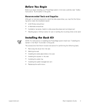
...assemblies in the rack • Installing the system in the rack • Installing the cable tray • Installing the cable-management arm • Replacing the rack's doors support.dell.com DELL CONFIDENTIAL - The subsections that follow include instructions for performing the following items make the installation easier:...tape or felt-tip marker, for use in marking the mounting holes to install the slide assemblies, you begin installing your PowerEdge system in the rack, carefully read "Safety Instructions" found later in this guide. Recommended Tools and Supplies Although no ...
...assemblies in the rack • Installing the system in the rack • Installing the cable tray • Installing the cable-management arm • Replacing the rack's doors support.dell.com DELL CONFIDENTIAL - The subsections that follow include instructions for performing the following items make the installation easier:...tape or felt-tip marker, for use in marking the mounting holes to install the slide assemblies, you begin installing your PowerEdge system in the rack, carefully read "Safety Instructions" found later in this guide. Recommended Tools and Supplies Although no ...

Rack Installation Guide
Page 28
... the cable-management arm on the vertical rail. Facing the back of the rack cabinet, attach the right-angle bracket of the PowerEdge chassis, so do not grasp the cable tray when lifting the system. The bracket slides into the square mounting holes on either side of the cable... tray. You should lift the system only by the chassis edges. DELL CONFIDENTIAL - cable tray 6-32 x 0.25-inch hex-head Phillips screws (5) Figure 11. Preliminary 9/8/00 14 Rack Installation Guide management arm to...
... the cable-management arm on the vertical rail. Facing the back of the rack cabinet, attach the right-angle bracket of the PowerEdge chassis, so do not grasp the cable tray when lifting the system. The bracket slides into the square mounting holes on either side of the cable... tray. You should lift the system only by the chassis edges. DELL CONFIDENTIAL - cable tray 6-32 x 0.25-inch hex-head Phillips screws (5) Figure 11. Preliminary 9/8/00 14 Rack Installation Guide management arm to...

Rack Installation Guide
Page 29
... its slotted pocket with the captive thumbscrew. support.dell.com DELL CONFIDENTIAL - Slide the unattached end of the cable-management arm into the slotted pocket made by the formed metal tabs on cable tray cablemanagement arm back of rack Velcro strap back of the cable tray. Preliminary 9/8/00 Rack Installation Guide 15 Installing the...
... its slotted pocket with the captive thumbscrew. support.dell.com DELL CONFIDENTIAL - Slide the unattached end of the cable-management arm into the slotted pocket made by the formed metal tabs on cable tray cablemanagement arm back of rack Velcro strap back of the cable tray. Preliminary 9/8/00 Rack Installation Guide 15 Installing the...

Rack Installation Guide
Page 31
...with the ring facing up . 7. Replace the second pull pin with the ring facing up . 9. Reversing the Cable-Management Arm 2. support.dell.com DELL CONFIDENTIAL - NOTE: Make note of the orientation of the cable-management arm. 3. Perform the steps to the opposite vertical rail. 8. Turn the... cable-management arm over (see Figure 13). The opposite vertical rail and the slotted pocket on the opposite side of the cable tray...
...with the ring facing up . 7. Replace the second pull pin with the ring facing up . 9. Reversing the Cable-Management Arm 2. support.dell.com DELL CONFIDENTIAL - NOTE: Make note of the orientation of the cable-management arm. 3. Perform the steps to the opposite vertical rail. 8. Turn the... cable-management arm over (see Figure 13). The opposite vertical rail and the slotted pocket on the opposite side of the cable tray...
Rack Installation Guide
Page 33
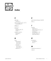
See ESD ESD, xv I installing cable tray, 14 cable-management arm, 14 computer, 12 rack adapters, 11, 12 shoulder screws, 11 slide assemblies, 8 K kit contents illustrated, 2 list of rack kit illustrated, 2 listed, 1 D doors opening latch 24-U rack, 6 42-U rack, 4 removing 24-U rack, 6 42-U rack, 4, 5 replacing, 18 E electrostatic discharge. Index C cable tray installing, 14 cable-management arm, 14, 16 routing cables, 16 cables, 16 cautions, ix computer installing in rack, 12 weight, 11 contents of , 1 N notational conventions, ix notes, ix support.dell.com Rack Installation Guide 1
See ESD ESD, xv I installing cable tray, 14 cable-management arm, 14 computer, 12 rack adapters, 11, 12 shoulder screws, 11 slide assemblies, 8 K kit contents illustrated, 2 list of rack kit illustrated, 2 listed, 1 D doors opening latch 24-U rack, 6 42-U rack, 4 removing 24-U rack, 6 42-U rack, 4, 5 replacing, 18 E electrostatic discharge. Index C cable tray installing, 14 cable-management arm, 14, 16 routing cables, 16 cables, 16 cautions, ix computer installing in rack, 12 weight, 11 contents of , 1 N notational conventions, ix notes, ix support.dell.com Rack Installation Guide 1

Tower Installation Guide
Page 5
... Tools 1-3 Installation 1-3 Shutting Down and Turning Off the System 1-3 Removing the Doors From a 24-U or 42-U Rack 1-4 Removing the Cable Management Arm 1-6 Removing the Cable Tray 1-7 Removing the System From the Rack 1-8 Removing the System 1-8 Removing the Rails and Rack Adapters 1-9 Removing the Slide Assemblies From the Rack 1-10 Replacing the...
... Tools 1-3 Installation 1-3 Shutting Down and Turning Off the System 1-3 Removing the Doors From a 24-U or 42-U Rack 1-4 Removing the Cable Management Arm 1-6 Removing the Cable Tray 1-7 Removing the System From the Rack 1-8 Removing the System 1-8 Removing the Rails and Rack Adapters 1-9 Removing the Slide Assemblies From the Rack 1-10 Replacing the...

Tower Installation Guide
Page 6
Removing the Cable Tray 1-8 Figure 1-7. Removing the System Cover 1-14 Figure 1-13. Removing the Front Bezel 1-15 iv Removing a Cage Nut 1-12 Figure 1-11. Installing the Rubber Feet 1-13 Figure 1-12. Removing the System From the Rack 1-9 Figure 1-8. Figure 1-6. Removing the Rails and Rack Adapters 1-10 Figure 1-9. Removing the Slide Assemblies 1-11 Figure 1-10.
Removing the Cable Tray 1-8 Figure 1-7. Removing the System Cover 1-14 Figure 1-13. Removing the Front Bezel 1-15 iv Removing a Cage Nut 1-12 Figure 1-11. Installing the Rubber Feet 1-13 Figure 1-12. Removing the System From the Rack 1-9 Figure 1-8. Figure 1-6. Removing the Rails and Rack Adapters 1-10 Figure 1-9. Removing the Slide Assemblies 1-11 Figure 1-10.

Tower Installation Guide
Page 9
.... Attach the cables and turn the system on installing the stabilizer feet. support.dell.com Dell PowerEdge 4x00 and 6300 Systems Tower Installation Guide 1-3 Remove the cable tray. 5. Shutting Down and Turning Off the System It is usually best to the Dell PowerEdge Rack-Mountable Solutions Installation Guide provided with the rack for detailed instructions): 1. The...
.... Attach the cables and turn the system on installing the stabilizer feet. support.dell.com Dell PowerEdge 4x00 and 6300 Systems Tower Installation Guide 1-3 Remove the cable tray. 5. Shutting Down and Turning Off the System It is usually best to the Dell PowerEdge Rack-Mountable Solutions Installation Guide provided with the rack for detailed instructions): 1. The...

Tower Installation Guide
Page 12
... the Velcro strips securing the cables to the cable tray on the back of the system, perform these steps: 1. Slide the system partially out of the rack and verify that the cable management arm and all attaching hardware, in a container for future use. 1-6 Dell PowerEdge 4x00 and 6300 Systems Tower Installation Guide Disconnect...
... the Velcro strips securing the cables to the cable tray on the back of the system, perform these steps: 1. Slide the system partially out of the rack and verify that the cable management arm and all attaching hardware, in a container for future use. 1-6 Dell PowerEdge 4x00 and 6300 Systems Tower Installation Guide Disconnect...

Tower Installation Guide
Page 13
support.dell.com Dell PowerEdge 4x00 and 6300 Systems Tower Installation Guide 1-7 Disconnecting the Cable Management Arm Removing the Cable Tray Remove the cable tray on the back of computer right-angle bracket cable tray 10-32 x 0.25-inch screws (3) Figure 1-5. 10-32 x 0.5-inch screw vertical rail cable-management arm back of the system by removing the five 6-32 x 0.25-inch Phillips-head screws that secure the tray to the system chassis (see Figure 1-6).
support.dell.com Dell PowerEdge 4x00 and 6300 Systems Tower Installation Guide 1-7 Disconnecting the Cable Management Arm Removing the Cable Tray Remove the cable tray on the back of computer right-angle bracket cable tray 10-32 x 0.25-inch screws (3) Figure 1-5. 10-32 x 0.5-inch screw vertical rail cable-management arm back of the system by removing the five 6-32 x 0.25-inch Phillips-head screws that secure the tray to the system chassis (see Figure 1-6).
Tower Installation Guide
Page 14
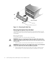
...never attempt to release the slide locks (see Figure 1-7), and then slide the system completely out of computer cable tray 6-32 x 0.25-inch screws (5) Figure 1-6. Removing the Cable Tray Removing the System From the Rack The subsections that follow include instructions for removing the system from the slide assemblies by... from the rack and removing the rails and other hardware associated with the rack installation of the system. back of the rack. 1-8 Dell PowerEdge 4x00 and 6300 Systems Tower Installation Guide Removing the System To remove the system from the rack, perform these steps.
...never attempt to release the slide locks (see Figure 1-7), and then slide the system completely out of computer cable tray 6-32 x 0.25-inch screws (5) Figure 1-6. Removing the Cable Tray Removing the System From the Rack The subsections that follow include instructions for removing the system from the slide assemblies by... from the rack and removing the rails and other hardware associated with the rack installation of the system. back of the rack. 1-8 Dell PowerEdge 4x00 and 6300 Systems Tower Installation Guide Removing the System To remove the system from the rack, perform these steps.

Tower Installation Guide
Page 22
Slide each drive. 7. Close the system board tray. Rotate the badge 90 degrees to record the power connector number and the location of the system. 3. Facing the outer side of the bezel, install ... To rotate the system badge on the opposite edge of the system, perform these steps: 1. Reinstall the system cover. 1-16 Dell PowerEdge 4x00 and 6300 Systems Tower Installation Guide Slide the system board tray out to match the new system orientation: a. Be sure to match the new orientation of the interface connector. b. Reconnect...
Slide each drive. 7. Close the system board tray. Rotate the badge 90 degrees to record the power connector number and the location of the system. 3. Facing the outer side of the bezel, install ... To rotate the system badge on the opposite edge of the system, perform these steps: 1. Reinstall the system cover. 1-16 Dell PowerEdge 4x00 and 6300 Systems Tower Installation Guide Slide the system board tray out to match the new system orientation: a. Be sure to match the new orientation of the interface connector. b. Reconnect...

Tower Installation Guide
Page 25
Index A arm cable management, 1-6 B badge reorienting, 1-16 bezel removing, 1-14 replacing, 1-16 C cable management arm removing, 1-6 cable tray removing, 1-7 cables connecting, 1-17 disconnecting, 1-6 cage nuts removing, 1-11 D doors opening latch, 1-4 removing, 1-4 replacing, 1-12 drives reorienting, 1-15 F feet installing, 1-13 K kit contents illustrated, 1-2 list of, 1-1 support.dell.com Index 1
Index A arm cable management, 1-6 B badge reorienting, 1-16 bezel removing, 1-14 replacing, 1-16 C cable management arm removing, 1-6 cable tray removing, 1-7 cables connecting, 1-17 disconnecting, 1-6 cage nuts removing, 1-11 D doors opening latch, 1-4 removing, 1-4 replacing, 1-12 drives reorienting, 1-15 F feet installing, 1-13 K kit contents illustrated, 1-2 list of, 1-1 support.dell.com Index 1

Installing VersaRails
Page 3
...the following items: One pair of VersaRails slide assemblies One cable management arm assembly Ten 10-32 x 0.500 Phillips-head screws One cable tray and five 6-32 x 0.25-inch hex head screws, for 4U and 7U systems only One pair of rack adapters and four 10...for 7U systems only One strain-relief bracket, for 2U systems only See the safety instructions provided in your Rack Installation Guide. support.dell.com Installing VersaRails 1-1 Before attempting this installation you should read through this entire document carefully. This document provides instructions for trained service ...
...the following items: One pair of VersaRails slide assemblies One cable management arm assembly Ten 10-32 x 0.500 Phillips-head screws One cable tray and five 6-32 x 0.25-inch hex head screws, for 4U and 7U systems only One pair of rack adapters and four 10...for 7U systems only One strain-relief bracket, for 2U systems only See the safety instructions provided in your Rack Installation Guide. support.dell.com Installing VersaRails 1-1 Before attempting this installation you should read through this entire document carefully. This document provides instructions for trained service ...