
Service Manual (.htm)
Page 3
...ft) of future options in Figure 1-1. See Figure 1-1. Processor Upgrade Installation Guide 1-1 NOTICE: Ensure that is installed in a ZIF socket on the system board. CAUTION: The processor and heat sink can upgrade your System Information Guide for complete information about safety precautions,... working inside the computer, and protecting against electrostatic discharge. Each processor and its side as shown in speed ...
...ft) of future options in Figure 1-1. See Figure 1-1. Processor Upgrade Installation Guide 1-1 NOTICE: Ensure that is installed in a ZIF socket on the system board. CAUTION: The processor and heat sink can upgrade your System Information Guide for complete information about safety precautions,... working inside the computer, and protecting against electrostatic discharge. Each processor and its side as shown in speed ...

Service Manual (.htm)
Page 4
www.dell.com | support.dell.com Figure 1-1. See Figure 1-2. 1-2 Processor Upgrade Installation Guide Opening the System padlock ring security cable slot buttons (2) (one on each side of the system) 6 Rotate the processor cooling shroud up to access the processor and heat sink.
www.dell.com | support.dell.com Figure 1-1. See Figure 1-2. 1-2 Processor Upgrade Installation Guide Opening the System padlock ring security cable slot buttons (2) (one on each side of the system) 6 Rotate the processor cooling shroud up to access the processor and heat sink.

Service Manual (.htm)
Page 5
See Figure 1-3. b While pulling the retention module tab out, lift the heat sink away from the processor. a Remove one retention module clip by pressing the tab on the clip and lifting the retention module clip up. Rotating the Processor Cooling Shroud cooling shroud 7 Remove the processor heat sink. Processor Upgrade Installation Guide 1-3 Figure 1-2.
See Figure 1-3. b While pulling the retention module tab out, lift the heat sink away from the processor. a Remove one retention module clip by pressing the tab on the clip and lifting the retention module clip up. Rotating the Processor Cooling Shroud cooling shroud 7 Remove the processor heat sink. Processor Upgrade Installation Guide 1-3 Figure 1-2.
Service Manual (.htm)
Page 6
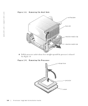
Removing the Processor release lever 1-4 Processor Upgrade Installation Guide processor socket See Figure 1-4. Figure 1-4. www.dell.com | support.dell.com Figure 1-3. Removing the Heat Sink cooling pipes heat sink retention module clip retention module tab 8 Pull the processor socket release lever straight up until the processor is released.
Removing the Processor release lever 1-4 Processor Upgrade Installation Guide processor socket See Figure 1-4. Figure 1-4. www.dell.com | support.dell.com Figure 1-3. Removing the Heat Sink cooling pipes heat sink retention module clip retention module tab 8 Pull the processor socket release lever straight up until the processor is released.

Service Manual (.htm)
Page 7
.... Figure 1-5. Processor Upgrade Installation Guide 1-5 NOTICE: Be careful not to seat it. 12 Rotate the release lever back toward the memory modules to prevent damage to system board components. Installing the Processor processor pin-1 indicator socket pin-1 indicator release lever processor socket 13 Remove... socket and press it snaps into place, securing the processor. Bending the pins can permanently damage the processor. 9 Remove the processor from the heat sink. See Figure 1-5. To avoid damage, ensure that the processor aligns properly with the socket, and do not use...
.... Figure 1-5. Processor Upgrade Installation Guide 1-5 NOTICE: Be careful not to seat it. 12 Rotate the release lever back toward the memory modules to prevent damage to system board components. Installing the Processor processor pin-1 indicator socket pin-1 indicator release lever processor socket 13 Remove... socket and press it snaps into place, securing the processor. Bending the pins can permanently damage the processor. 9 Remove the processor from the heat sink. See Figure 1-5. To avoid damage, ensure that the processor aligns properly with the socket, and do not use...

Service Manual (.htm)
Page 8
See Figure 1-3. 15 Replace the retention module clip by pressing in the retention module. See Figure 1-3. 16 Rotate the processor cooling shroud down and into the retention module. See Figure 1-2. 17 Close the system cover: a Pivot the cover down . b Press down on ... retention module tab on the side opposite the removed clip, and lower the heat sink onto the processor until the heat sink snaps securely in on the system and attached peripherals. 1-6 Processor Upgrade Installation Guide www.dell.com | support.dell.com 14 Place one end of the clip into position. See Figure 1-1.
See Figure 1-3. 15 Replace the retention module clip by pressing in the retention module. See Figure 1-3. 16 Rotate the processor cooling shroud down and into the retention module. See Figure 1-2. 17 Close the system cover: a Pivot the cover down . b Press down on ... retention module tab on the side opposite the removed clip, and lower the heat sink onto the processor until the heat sink snaps securely in on the system and attached peripherals. 1-6 Processor Upgrade Installation Guide www.dell.com | support.dell.com 14 Place one end of the clip into position. See Figure 1-1.


