
Installing a SATA Optical Drive
Page 1
Dell™ PowerEdge™ 19x0 and 29x0 Systems Installing a SATA Optical Drive
Dell™ PowerEdge™ 19x0 and 29x0 Systems Installing a SATA Optical Drive

Installing a SATA Optical Drive
Page 3
...tab at the top of the peripheral bay and remove the optical drive from the back of the optical drive. 6 PowerEdge 2900 and 1900 systems only: Perform the following steps. Installing a SATA Optical Drive 3 All Systems 1 Turn off the system and attached peripherals, and... technicians are authorized to which a SATA optical drive is being added, or in your Hardware Owner's Manual. 4 PowerEdge 1950 systems only: Disconnect and remove the SAS controller daughter card. Installing a SATA Optical Drive These instructions apply to Dell™ PowerEdge™ systems to remove the system...
...tab at the top of the peripheral bay and remove the optical drive from the back of the optical drive. 6 PowerEdge 2900 and 1900 systems only: Perform the following steps. Installing a SATA Optical Drive 3 All Systems 1 Turn off the system and attached peripherals, and... technicians are authorized to which a SATA optical drive is being added, or in your Hardware Owner's Manual. 4 PowerEdge 1950 systems only: Disconnect and remove the SAS controller daughter card. Installing a SATA Optical Drive These instructions apply to Dell™ PowerEdge™ systems to remove the system...
Installing a SATA Optical Drive
Page 4
... on the interposer board release tab and simultaneously pull up on the carrier fit into place. PowerEdge 2970, 2950, and 1950 For PowerEdge 2970 and 2950 systems, the optical drive tray that shipped with the SATA drive installation kit. Preparing the Optical Drive Tray - See Figure 1-1. 5 Lower the left side of the tray. If you must be replaced...
... on the interposer board release tab and simultaneously pull up on the carrier fit into place. PowerEdge 2970, 2950, and 1950 For PowerEdge 2970 and 2950 systems, the optical drive tray that shipped with the SATA drive installation kit. Preparing the Optical Drive Tray - See Figure 1-1. 5 Lower the left side of the tray. If you must be replaced...

Installing a SATA Optical Drive
Page 5
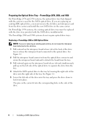
... 1-2. Release the rails to attach the drive to the old drive. Installing a SATA Optical Drive 5 Replacing the Optical Drive in a PowerEdge 2950 or 2970 System 2 1 3 4 5 6 7 1 optical drive 3 interposer 5 SATA power cable 7 optical drive carrier 2 interposer release latch 4 SATA cable 6 carrier latch Replacing a PowerEdge 1950 Optical Drive NOTE: The replacement drive tray provided in the side of the drive. Spread the side rails of the replacement...
... 1-2. Release the rails to attach the drive to the old drive. Installing a SATA Optical Drive 5 Replacing the Optical Drive in a PowerEdge 2950 or 2970 System 2 1 3 4 5 6 7 1 optical drive 3 interposer 5 SATA power cable 7 optical drive carrier 2 interposer release latch 4 SATA cable 6 carrier latch Replacing a PowerEdge 1950 Optical Drive NOTE: The replacement drive tray provided in the side of the drive. Spread the side rails of the replacement...

Installing a SATA Optical Drive
Page 6
... the cable through the power cable cutout in a PowerEdge 1950 Drive Tray 2 3 1 4 5 1 optical drive 3 SATA power cable 5 optical drive carrier 2 SATA cable 4 carrier latch Installing the SATA Optical Drive - Installing a SATA Optical Drive in the fan bracket and follow the power cable routing to the power supply connector. PowerEdge 1950 1 Insert the optical drive tray into the system until it is fully...
... the cable through the power cable cutout in a PowerEdge 1950 Drive Tray 2 3 1 4 5 1 optical drive 3 SATA power cable 5 optical drive carrier 2 SATA cable 4 carrier latch Installing the SATA Optical Drive - Installing a SATA Optical Drive in the fan bracket and follow the power cable routing to the power supply connector. PowerEdge 1950 1 Insert the optical drive tray into the system until it is fully...

Installing a SATA Optical Drive
Page 7
... Hardware Owner's Manual. 6 Close the system. Installing a SATA Optical Drive 7 PowerEdge 2970 or 2950 1 Insert the optical drive tray into the system until it is fully inserted and locked into position. 2 Connect the SATA cable (the end with the branching power cable) to the back of the optical drive. 3 Connect the branching power cable to power and...
... Hardware Owner's Manual. 6 Close the system. Installing a SATA Optical Drive 7 PowerEdge 2970 or 2950 1 Insert the optical drive tray into the system until it is fully inserted and locked into position. 2 Connect the SATA cable (the end with the branching power cable) to the back of the optical drive. 3 Connect the branching power cable to power and...

Installing a SATA Optical Drive
Page 8
... detaches from the chassis slots. 6 Route the SATA cable in the cable channel in the PowerEdge 2950 and 2970 1 2 3 4 5 1 SATA_B connector on the system board. SATA Cable Routing in the right wall of the cable... retention bracket to the central riser. 8 Bend the cable behind the central riser and connect the cable to the SATA_B connector on system board 2 cable retention bracket 3 SATA data cable 4 SATA power cable 5 optical drive 8 Installing a SATA...
... detaches from the chassis slots. 6 Route the SATA cable in the cable channel in the PowerEdge 2950 and 2970 1 2 3 4 5 1 SATA_B connector on the system board. SATA Cable Routing in the right wall of the cable... retention bracket to the central riser. 8 Bend the cable behind the central riser and connect the cable to the SATA_B connector on system board 2 cable retention bracket 3 SATA data cable 4 SATA power cable 5 optical drive 8 Installing a SATA...

Installing a SATA Optical Drive
Page 9
... the CD/TBU connector on the system and attached peripherals. For a PowerEdge 2900, use the SATA_D connector. Installing the SATA Optical Drive - For a PowerEdge 1900, use the SATA_B connector. - For a PowerEdge 1900 system, connect to the system board over the top of the optical drive. 4 Use the appropriate power cable provided in your Hardware Owner's Manual...
... the CD/TBU connector on the system and attached peripherals. For a PowerEdge 2900, use the SATA_D connector. Installing the SATA Optical Drive - For a PowerEdge 1900, use the SATA_B connector. - For a PowerEdge 1900 system, connect to the system board over the top of the optical drive. 4 Use the appropriate power cable provided in your Hardware Owner's Manual...

Installing a SATA Optical Drive
Page 10
Figure 1-5. See "Closing the System" in a PowerEdge 2900 or 1900 3 2 4 5 1 1 optical drive 3 SATA data cable 5 SATA power connector on SAS backplane (PowerEdge 2900 only) 2 SATA power cable 4 SATA connector on system board 8 Reconnect the cables to power and turn on the system and attached peripherals. 10 Installing a SATA Optical Drive SATA Cable Routing in your Hardware Owner's Manual. 10 Reconnect the system to the SAS controller daughter card. 9 Close the system.
Figure 1-5. See "Closing the System" in a PowerEdge 2900 or 1900 3 2 4 5 1 1 optical drive 3 SATA data cable 5 SATA power connector on SAS backplane (PowerEdge 2900 only) 2 SATA power cable 4 SATA connector on system board 8 Reconnect the cables to power and turn on the system and attached peripherals. 10 Installing a SATA Optical Drive SATA Cable Routing in your Hardware Owner's Manual. 10 Reconnect the system to the SAS controller daughter card. 9 Close the system.

Getting Started Guide
Page 5
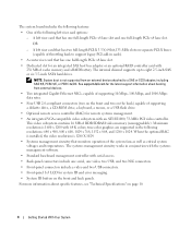
... heat sink, and fan as well as the instructions for up to six 3.5-inch, internal hot-pluggable Serial Attached SCSI (SAS) or SATA hard drives without optional media bay, or up to a maximum of 32 GB by installing combinations of the Intel Xeon processor will work properly as ... kit from Dell. Getting Started With Your System 3 NOTE: DVD devices are installed. • Support for performing the upgrade. • A minimum of 512 MB of 533 or 667 (when available) MHz, Fully Buffered DIMMs (FBD), upgradable to four 3.5-inch internal hot-pluggable SAS or SATA hard drives with optional ...
... heat sink, and fan as well as the instructions for up to six 3.5-inch, internal hot-pluggable Serial Attached SCSI (SAS) or SATA hard drives without optional media bay, or up to a maximum of 32 GB by installing combinations of the Intel Xeon processor will work properly as ... kit from Dell. Getting Started With Your System 3 NOTE: DVD devices are installed. • Support for performing the upgrade. • A minimum of 512 MB of 533 or 667 (when available) MHz, Fully Buffered DIMMs (FBD), upgradable to four 3.5-inch internal hot-pluggable SAS or SATA hard drives with optional ...
Getting Started Guide
Page 6
See support.dell.com for the latest support information about specific features, see "Technical ... 2.0-compliant connectors (two on the front and two on the back) capable of supporting a diskette drive, a CD-ROM drive, a keyboard, a mouse, or a USB flash drive. • Optional remote access controller (RAC) for system ID and error messaging. • System... ID button on separate PCI-X buses (capable of throttling back to eight 2.5-inch SAS or six 3.5-inch SATA hard drives. The internal channel supports up to support legacy PCI add-in cards). • A center riser card that has...
See support.dell.com for the latest support information about specific features, see "Technical ... 2.0-compliant connectors (two on the front and two on the back) capable of supporting a diskette drive, a CD-ROM drive, a keyboard, a mouse, or a USB flash drive. • Optional remote access controller (RAC) for system ID and error messaging. • System... ID button on separate PCI-X buses (capable of throttling back to eight 2.5-inch SAS or six 3.5-inch SATA hard drives. The internal channel supports up to support legacy PCI add-in cards). • A center riser card that has...

Getting Started Guide
Page 12
...32 GB up to six 3.5-inch, internal hot-pluggable SAS or SATA hard drives without optional media bay, OR up to four 3.5-inch internal hot-pluggable SAS or SATA hard drives with optional media bay OR eight 2.5-inch internal hot-pluggable SAS hard drives one optional 3.5-inch, 1.44-MB external optional USB 3.5-inch,... Center riser: PCIe Left riser PCI-X option: PCIe option: Memory Architecture Memory module sockets Memory module capacities Minimum RAM Maximum RAM Drives Hard drives Diskette drive 10 Getting Started With Your System One or two Dual-Core Intel Xeon Processors 5000 Sequence.
...32 GB up to six 3.5-inch, internal hot-pluggable SAS or SATA hard drives without optional media bay, OR up to four 3.5-inch internal hot-pluggable SAS or SATA hard drives with optional media bay OR eight 2.5-inch internal hot-pluggable SAS hard drives one optional 3.5-inch, 1.44-MB external optional USB 3.5-inch,... Center riser: PCIe Left riser PCI-X option: PCIe option: Memory Architecture Memory module sockets Memory module capacities Minimum RAM Maximum RAM Drives Hard drives Diskette drive 10 Getting Started With Your System One or two Dual-Core Intel Xeon Processors 5000 Sequence.
Hardware Owner's Manual (PDF)
Page 4
... Before You Begin 56 Removing a Drive Blank 56 Installing a Drive Blank 57 Removing a Hot-Plug Hard Drive 57 Installing a Hot-Plug Hard Drive 57 Replacing a Hard-Drive Carrier 58 Removing a Hard Drive From a Hard-Drive Carrier 58 Installing a SAS Hard Drive Into a SATAu Drive Carrier 59 Installing a SATA Hard Drive Into a SATA Drive Carrier 60 Installing a SATA Hard Drive and Interposer Card Into a SATAu Hard...
... Before You Begin 56 Removing a Drive Blank 56 Installing a Drive Blank 57 Removing a Hot-Plug Hard Drive 57 Installing a Hot-Plug Hard Drive 57 Replacing a Hard-Drive Carrier 58 Removing a Hard Drive From a Hard-Drive Carrier 58 Installing a SAS Hard Drive Into a SATAu Drive Carrier 59 Installing a SATA Hard Drive Into a SATA Drive Carrier 60 Installing a SATA Hard Drive and Interposer Card Into a SATAu Hard...

Hardware Owner's Manual (PDF)
Page 39
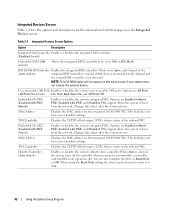
... X Description Resets the time on the system's internal calendar. Enable or disable Hyper-Threading technology by changing the setting of SATA drive attached to Port X. NOTE: The options for the information fields that appear on the system configuration. See Table 2-3. Displays type and capacity of the Logical ...
... X Description Resets the time on the system's internal calendar. Enable or disable Hyper-Threading technology by changing the setting of SATA drive attached to Port X. NOTE: The options for the information fields that appear on the system configuration. See Table 2-3. Displays type and capacity of the Logical ...
Hardware Owner's Manual (PDF)
Page 42
...Auto default) Enables or disables the system's diskette drive controller. Integrated Devices Screen Options Option Description Integrated SAS Controller Enables or disables the integrated SAS controller. (Enabled default) Embedded SATA (Off default) Allows the integrated SATA controller to be used to write to boot ... of the onboard NIC. IDE CD-ROM Controller Enables the integrated IDE controller. When using the Read-Only setting, the drive cannot be set to accommodate a controller card installed in an expansion slot. Integrated Devices Screen Table 2-4 lists the options ...
...Auto default) Enables or disables the system's diskette drive controller. Integrated Devices Screen Options Option Description Integrated SAS Controller Enables or disables the integrated SAS controller. (Enabled default) Embedded SATA (Off default) Allows the integrated SATA controller to be used to write to boot ... of the onboard NIC. IDE CD-ROM Controller Enables the integrated IDE controller. When using the Read-Only setting, the drive cannot be set to accommodate a controller card installed in an expansion slot. Integrated Devices Screen Table 2-4 lists the options ...
Hardware Owner's Manual (PDF)
Page 52
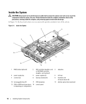
... bay 5 power supplies (2) 6 left riser 7 central riser 8 memory modules (8) 9 heatsinks and microprocessors (2) 10 hot-pluggable fans (4) 11 SAS backplane 12 slimline optical drive (optional) 13 SAS or SATA hard drives (up to remove the system cover and access any of the system. Figure 3-1. See your Product Information Guide for complete information about safety...
... bay 5 power supplies (2) 6 left riser 7 central riser 8 memory modules (8) 9 heatsinks and microprocessors (2) 10 hot-pluggable fans (4) 11 SAS backplane 12 slimline optical drive (optional) 13 SAS or SATA hard drives (up to remove the system cover and access any of the system. Figure 3-1. See your Product Information Guide for complete information about safety...

Hardware Owner's Manual (PDF)
Page 55
... to the system board through one of the system and offset the cover slightly back so that allows your SATA drive to attach to secure the cover. Your system features up the latch on the cover. 2 Place the cover on the system chassis. Removing the Cover 1 2 3... 1 latch 2 latch release lock 3 alignment J hooks Hard Drives This subsection describes how to install and configure SAS or SATA hard drives in a clockwise direction to the SAS connector on these backplane options.
... to the system board through one of the system and offset the cover slightly back so that allows your SATA drive to attach to secure the cover. Your system features up the latch on the cover. 2 Place the cover on the system chassis. Removing the Cover 1 2 3... 1 latch 2 latch release lock 3 alignment J hooks Hard Drives This subsection describes how to install and configure SAS or SATA hard drives in a clockwise direction to the SAS connector on these backplane options.
Hardware Owner's Manual (PDF)
Page 56
... received one of the following two drive carrier types: • SATA drive carrier - A 9-GB hard drive, for the formatting to be completed. See Figure 3-4. 3 Slide the drive blank out until the blank is running, see the documentation for these drives are supplied in special hot-pluggable drive carriers that makes the SATA hard drive usable in some storage systems...
... received one of the following two drive carrier types: • SATA drive carrier - A 9-GB hard drive, for the formatting to be completed. See Figure 3-4. 3 Slide the drive blank out until the blank is running, see the documentation for these drives are supplied in special hot-pluggable drive carriers that makes the SATA hard drive usable in some storage systems...

Hardware Owner's Manual (PDF)
Page 60
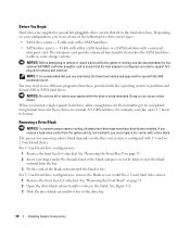
... must be installed in SATA drive carriers (labeled "SATA"). Installing a SATA Hard Drive Into a SATA Drive Carrier 1 2 3 1 screws (4) 2 SATA drive carrier 3 SATA hard drive 60 Installing System Components Installing a SATA Hard Drive Into a SATA Drive Carrier NOTE: SATA hard drives that connect directly to the hard-drive carrier. Only SATA hard drives with interposer cards can be installed in SATAu drive carriers. 1 Insert the SATA hard drive into the hard-drive carrier with the...
... must be installed in SATA drive carriers (labeled "SATA"). Installing a SATA Hard Drive Into a SATA Drive Carrier 1 2 3 1 screws (4) 2 SATA drive carrier 3 SATA hard drive 60 Installing System Components Installing a SATA Hard Drive Into a SATA Drive Carrier NOTE: SATA hard drives that connect directly to the hard-drive carrier. Only SATA hard drives with interposer cards can be installed in SATAu drive carriers. 1 Insert the SATA hard drive into the hard-drive carrier with the...

Hardware Owner's Manual (PDF)
Page 178
... battery, 74 installing (continued) SAS backplane board, 104 SAS controller daughter card, 70 SAS hard drive in a SATAu drive carrier, 59 SATA hard drive in a SATA drive carrier, 60 SATA hard drive in a SATAu drive carrier, 61 sideplane board, 102 system board, 108 tape drive, 86 integrated NIC TOE activating, 93 IRQs avoiding conflicts, 112 line assignments, 112 J jumpers system...
... battery, 74 installing (continued) SAS backplane board, 104 SAS controller daughter card, 70 SAS hard drive in a SATAu drive carrier, 59 SATA hard drive in a SATA drive carrier, 60 SATA hard drive in a SATAu drive carrier, 61 sideplane board, 102 system board, 108 tape drive, 86 integrated NIC TOE activating, 93 IRQs avoiding conflicts, 112 line assignments, 112 J jumpers system...


