Getting Started Guide
Page 5
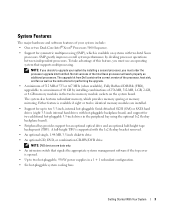
... the correct version of the processor, heat sink, and fan as well as additional processors. The upgrade kit from Dell. NOTE: If you must use an operating system that signals the appropriate systems management software if the top cover is supported ...3.5-inch, internal hot-pluggable Serial-Attached SCSI (SAS) or SATA hard drives (eight 3.5-inch internal hard drives with the 1x2 flexbay bracket removed. • An optional single, 1.44-MB, 3.5-inch diskette drive. • An optional CD, DVD, or combination CD-RW/DVD drive. NOTE: DVD devices are installed. • Support for up ...
... the correct version of the processor, heat sink, and fan as well as additional processors. The upgrade kit from Dell. NOTE: If you must use an operating system that signals the appropriate systems management software if the top cover is supported ...3.5-inch, internal hot-pluggable Serial-Attached SCSI (SAS) or SATA hard drives (eight 3.5-inch internal hard drives with the 1x2 flexbay bracket removed. • An optional single, 1.44-MB, 3.5-inch diskette drive. • An optional CD, DVD, or combination CD-RW/DVD drive. NOTE: DVD devices are installed. • Support for up ...
Getting Started Guide
Page 12
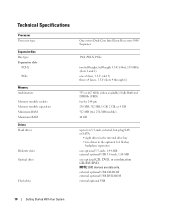
... type Expansion Bus Bus type Expansion slots PCI-X PCIe Memory Architecture Memory module sockets Memory module capacities Minimum RAM Maximum RAM Drives Hard drives Diskette drive Optical drive Flash drive One or two Dual-Core Intel Xeon Processors 5000 Sequence PCI, PCI-X, PCIe two full-height, full-length 3.3-V, 64-...MB (two 256-MB module) 48 GB up to ten 3.5-inch, internal, hot-plug SAS or SATA • eight drives in the internal drive bay • two drives in the optional 1x2 flexbay backplane expansion one optional 3.5-inch, 1.44-MB external optional USB 3.5-inch, 1.44-MB one optional...
... type Expansion Bus Bus type Expansion slots PCI-X PCIe Memory Architecture Memory module sockets Memory module capacities Minimum RAM Maximum RAM Drives Hard drives Diskette drive Optical drive Flash drive One or two Dual-Core Intel Xeon Processors 5000 Sequence PCI, PCI-X, PCIe two full-height, full-length 3.3-V, 64-...MB (two 256-MB module) 48 GB up to ten 3.5-inch, internal, hot-plug SAS or SATA • eight drives in the internal drive bay • two drives in the optional 1x2 flexbay backplane expansion one optional 3.5-inch, 1.44-MB external optional USB 3.5-inch, 1.44-MB one optional...
Hardware Owner's Manual (PDF)
Page 3
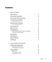
Contents 1 About Your System System Orientation 10 Other Information You May Need 10 Accessing System Features During Startup 11 Front-Panel Features and Indicators 12 Hard-Drive Indicator Codes 14 Back-Panel Features and Indicators 16 Connecting External Devices 16 Power Indicator Codes 17 NIC Indicator Codes 18 LCD Status Messages 18 ...
Contents 1 About Your System System Orientation 10 Other Information You May Need 10 Accessing System Features During Startup 11 Front-Panel Features and Indicators 12 Hard-Drive Indicator Codes 14 Back-Panel Features and Indicators 16 Connecting External Devices 16 Power Indicator Codes 17 NIC Indicator Codes 18 LCD Status Messages 18 ...
Hardware Owner's Manual (PDF)
Page 4
... 53 Hot-Plug Hard Drives 54 Before You Begin 55 Removing a Drive Blank 56 Installing a Drive Blank 56 Removing a Hot-Plug Hard Drive 56 Installing a Hot-Plug Hard Drive 56 Replacing a Hard-Drive Carrier 58 Removing a Hard Drive From a Hard-Drive Carrier 58 Installing a SAS Hard Drive Into a SATAu Drive Carrier 58 Installing a SATA Hard Drive Into a SATA Drive Carrier 59 Installing a SATA Hard Drive and Interposer Card Into a SATAu Hard-Drive Carrier 60...
... 53 Hot-Plug Hard Drives 54 Before You Begin 55 Removing a Drive Blank 56 Installing a Drive Blank 56 Removing a Hot-Plug Hard Drive 56 Installing a Hot-Plug Hard Drive 56 Replacing a Hard-Drive Carrier 58 Removing a Hard Drive From a Hard-Drive Carrier 58 Installing a SAS Hard Drive Into a SATAu Drive Carrier 58 Installing a SATA Hard Drive Into a SATA Drive Carrier 59 Installing a SATA Hard Drive and Interposer Card Into a SATAu Hard-Drive Carrier 60...

Hardware Owner's Manual (PDF)
Page 7
... 122 Troubleshooting Power Supplies 122 Troubleshooting System Cooling Problems 123 Troubleshooting a Fan 123 Troubleshooting System Memory 124 Troubleshooting a Diskette Drive 126 Troubleshooting an Optical Drive 127 Troubleshooting an External SCSI Tape Drive 128 Troubleshooting a Hard Drive 129 Troubleshooting a SAS or SAS RAID Controller Daughter Card 130 Troubleshooting Expansion Cards 131 Troubleshooting the Microprocessors 133 5 Running...
... 122 Troubleshooting Power Supplies 122 Troubleshooting System Cooling Problems 123 Troubleshooting a Fan 123 Troubleshooting System Memory 124 Troubleshooting a Diskette Drive 126 Troubleshooting an Optical Drive 127 Troubleshooting an External SCSI Tape Drive 128 Troubleshooting a Hard Drive 129 Troubleshooting a SAS or SAS RAID Controller Daughter Card 130 Troubleshooting Expansion Cards 131 Troubleshooting the Microprocessors 133 5 Running...

Hardware Owner's Manual (PDF)
Page 13
... Eight hot-pluggable bays for two additional 3.5-inch, hot-pluggable SAS or SATA hard drives. Optional flex bay drive bracket with 1x2 SAS backplane for 3.5-inch SAS or SATA hard drives connected to AC power and an error has been detected, the LCD lights amber... Components (continued) Item Component Icon 3 System identification button 4 LCD panel 5 USB connectors (2) 6 Video connector 7 Diskette drive 8 Hard drives 9 Flex bay 10 Tape backup unit 11 Optical drive Description The identification buttons on the front and back of these buttons is pushed again. Optional.
... Eight hot-pluggable bays for two additional 3.5-inch, hot-pluggable SAS or SATA hard drives. Optional flex bay drive bracket with 1x2 SAS backplane for 3.5-inch SAS or SATA hard drives connected to AC power and an error has been detected, the LCD lights amber... Components (continued) Item Component Icon 3 System identification button 4 LCD panel 5 USB connectors (2) 6 Video connector 7 Diskette drive 8 Hard drives 9 Flex bay 10 Tape backup unit 11 Optical drive Description The identification buttons on the front and back of these buttons is pushed again. Optional.
Hardware Owner's Manual (PDF)
Page 14
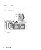
See Figure 1-3. Figure 1-3. Hard-Drive Indicator Codes The hard-drive carriers have two indicators-the drive-activity indicator and the drive-status indicator. In RAID configurations, the drive-status indicator lights to indicate the status of the drive. In non-RAID configurations, only the drive-activity indicator lights; the drive-status indicator is off. Hard-Drive Indicators 1 2 1 drive-status indicator (green 2 green drive-activity indicator and amber) 14 About Your System
See Figure 1-3. Figure 1-3. Hard-Drive Indicator Codes The hard-drive carriers have two indicators-the drive-activity indicator and the drive-status indicator. In RAID configurations, the drive-status indicator lights to indicate the status of the drive. In non-RAID configurations, only the drive-activity indicator lights; the drive-status indicator is off. Hard-Drive Indicators 1 2 1 drive-status indicator (green 2 green drive-activity indicator and amber) 14 About Your System
Hardware Owner's Manual (PDF)
Page 15
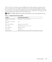
... example, if a hard drive fails, the "drive failed" pattern appears. After the drive is installed, the "drive being prepared for removal" pattern appears, followed by the "drive online" pattern. Blinks green slowly. After the replacement drive is selected for removal, the "drive being prepared for insertion or removal Drive predicted failure Drive failed Drive rebuilding Drive online Rebuild aborted Drive-Status Indicator Pattern...
... example, if a hard drive fails, the "drive failed" pattern appears. After the drive is installed, the "drive being prepared for removal" pattern appears, followed by the "drive online" pattern. Blinks green slowly. After the replacement drive is selected for removal, the "drive being prepared for insertion or removal Drive predicted failure Drive failed Drive rebuilding Drive online Rebuild aborted Drive-Status Indicator Pattern...
Hardware Owner's Manual (PDF)
Page 22
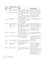
...at buss ##, device ##, Expansion Cards" on a component that resides in slot #. Remove and reseat the PCI expansion cards. See "Troubleshooting a Hard Drive" on page 147. If the problem persists, see "Troubleshooting Expansion Cards" on page 131. removed from the system. seated properly. See PCI ... the PCI PCI system error on page 147. If the problem persists, see your RAID documentation. HDD ## Rbld Abrt The specified hard drive has experienced a rebuild abort. If the problem persists, the system board is or bad. PBD Pwr Cable The power distribution board ...
...at buss ##, device ##, Expansion Cards" on a component that resides in slot #. Remove and reseat the PCI expansion cards. See "Troubleshooting a Hard Drive" on page 147. If the problem persists, see "Troubleshooting Expansion Cards" on page 131. removed from the system. seated properly. See PCI ... the PCI PCI system error on page 147. If the problem persists, see your RAID documentation. HDD ## Rbld Abrt The specified hard drive has experienced a rebuild abort. If the problem persists, the system board is or bad. PBD Pwr Cable The power distribution board ...

Hardware Owner's Manual (PDF)
Page 30
... the PCIe card in the specified slot. If the problem persists, see "Troubleshooting a Diskette Drive" on page 126, "Troubleshooting an Optical Drive" on page 127, and "Troubleshooting a Hard Drive" on page 147. 30 About Your System See "Using the System Setup Program" on page...Getting Help" on your operating system documentation. Corrective Actions Use a bootable diskette, CD, or hard drive. If the problem persists, see "Getting Help" on hard drive. See your hard drive. Faulty or improperly installed PCIe card in the specified slot number. See "Expansion Cards" on...
... the PCIe card in the specified slot. If the problem persists, see "Troubleshooting a Diskette Drive" on page 126, "Troubleshooting an Optical Drive" on page 127, and "Troubleshooting a Hard Drive" on page 147. 30 About Your System See "Using the System Setup Program" on page...Getting Help" on your operating system documentation. Corrective Actions Use a bootable diskette, CD, or hard drive. If the problem persists, see "Getting Help" on hard drive. See your hard drive. Faulty or improperly installed PCIe card in the specified slot number. See "Expansion Cards" on...

Hardware Owner's Manual (PDF)
Page 31
... request. If memory has been added or removed, this message is informative and can be faulty. Ensure that the diskette and hard drive cables are securely shadowing. Remote configuration update attempt failed System unable to the expansion cards. If memory has not been added or...module. If the problem persists, see "Troubleshooting Expansion Cards" on page 129 for jumper location. Sector not found from the diskette or hard drive, the system could not find a particular sector on page 131. Ensure that checksum failure is defective. Read fault The operating system ...
... request. If memory has been added or removed, this message is informative and can be faulty. Ensure that the diskette and hard drive cables are securely shadowing. Remote configuration update attempt failed System unable to the expansion cards. If memory has not been added or...module. If the problem persists, see "Troubleshooting Expansion Cards" on page 129 for jumper location. Sector not found from the diskette or hard drive, the system could not find a particular sector on page 131. Ensure that checksum failure is defective. Read fault The operating system ...
Hardware Owner's Manual (PDF)
Page 32
... System See system battery. See the CDs that came with an error. See "Getting Help" on the boot hard drive. DIMM y Ensure that only Dell-qualified memory is not supported by Install a supported microprocessor or the system. Utility partition not available The key was...is used . Embedded RAID firmware responds with your system. Create a utility partition on the boot hard drive. Dell recommends purchasing memory upgrade kits directly from www.dell.com or your Dell sales agent to ensure compatibility. Warning: Embedded RAID error! Ensure that only ECC FBD1 memory is ...
... System See system battery. See the CDs that came with an error. See "Getting Help" on the boot hard drive. DIMM y Ensure that only Dell-qualified memory is not supported by Install a supported microprocessor or the system. Utility partition not available The key was...is used . Embedded RAID firmware responds with your system. Create a utility partition on the boot hard drive. Dell recommends purchasing memory upgrade kits directly from www.dell.com or your Dell sales agent to ensure compatibility. Warning: Embedded RAID error! Ensure that only ECC FBD1 memory is ...

Hardware Owner's Manual (PDF)
Page 33
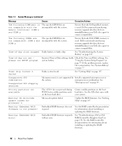
... fault on page 129. See "Troubleshooting a Diskette Drive" on page 126, "Troubleshooting an Optical Drive" on page 127, or "Troubleshooting a Hard Drive" on selected drive Faulty diskette, optical/diskette drive assembly, hard drive, or hard-drive subsystem. For more information, see the documentation that ...Memory" on the diskette. System Messages (continued) Message Causes Corrective Actions Warning: The current memory configuration is not optimal. Dell recommends a population of the Diagnostics Checklist in "Getting Help" on page 147, and then follow the instructions in this...
... fault on page 129. See "Troubleshooting a Diskette Drive" on page 126, "Troubleshooting an Optical Drive" on page 127, or "Troubleshooting a Hard Drive" on selected drive Faulty diskette, optical/diskette drive assembly, hard drive, or hard-drive subsystem. For more information, see the documentation that ...Memory" on the diskette. System Messages (continued) Message Causes Corrective Actions Warning: The current memory configuration is not optimal. Dell recommends a population of the Diagnostics Checklist in "Getting Help" on page 147, and then follow the instructions in this...
Hardware Owner's Manual (PDF)
Page 38
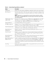
Available options can include the diskette drive, CD drive, hard drives, and network. NOTE: System boot is attached to the system. Hard disk allows the USB flash drive to Port X on page 40. Auto automatically chooses an emulation type. Displays a screen to configure the front-panel LCD ... Program Displays a screen to set a userdefined LCD string. Select Do Not Report to suppress all error messages relating to act as a hard drive. See support.dell.com for more information. Displays a screen to 84-key keyboards). See "Using the System Password" on page 43 and "Using the Setup...
Available options can include the diskette drive, CD drive, hard drives, and network. NOTE: System boot is attached to the system. Hard disk allows the USB flash drive to Port X on page 40. Auto automatically chooses an emulation type. Displays a screen to configure the front-panel LCD ... Program Displays a screen to set a userdefined LCD string. Select Do Not Report to suppress all error messages relating to act as a hard drive. See support.dell.com for more information. Displays a screen to 84-key keyboards). See "Using the System Password" on page 43 and "Using the Setup...

Hardware Owner's Manual (PDF)
Page 49
Installing System Components This section describes how to install the following system components: • Hot-plug hard drives • Power supplies • Cooling fans • Expansion cards • Tape, optical, and diskette drives • System battery • System memory • RAC card • Microprocessors • SAS backplane board • SAS controller daughter card •...
Installing System Components This section describes how to install the following system components: • Hot-plug hard drives • Power supplies • Cooling fans • Expansion cards • Tape, optical, and diskette drives • System battery • System memory • RAC card • Microprocessors • SAS backplane board • SAS controller daughter card •...
Hardware Owner's Manual (PDF)
Page 54
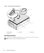
NOTE: For the tower orientation, drive bays 8 and 9 are numbered in the rack-mount orientation. Figure 3-4. Installing and Removing the System Cover 1 2 3 4 1 latch release lock 4 cover latch 2 system cover 3 chassis hooks Hot-Plug Hard Drives Figure 3-5 shows how the SAS/SATA hot-plug drive bays are reversed. 54 Installing System Components
NOTE: For the tower orientation, drive bays 8 and 9 are numbered in the rack-mount orientation. Figure 3-4. Installing and Removing the System Cover 1 2 3 4 1 latch release lock 4 cover latch 2 system cover 3 chassis hooks Hot-Plug Hard Drives Figure 3-5 shows how the SAS/SATA hot-plug drive bays are reversed. 54 Installing System Components
Hardware Owner's Manual (PDF)
Page 55
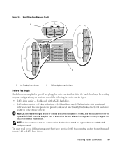
... interposer card. Hard-Drive Bay Numbers (Rack) 1 2 1 1x2 flex bay hard drives 2 1x8 backplane hard drives Before You Begin Hard drives are supplied in the hard-drive bays. You may need to use with the operating system to support hotplug drive removal and insertion. Installing System Components 55 Figure 3-5. Usable with either a SAS hard drive or a SATA hard drive with a SATA hard drive. • SATAu drive carrier - NOTE...
... interposer card. Hard-Drive Bay Numbers (Rack) 1 2 1 1x2 flex bay hard drives 2 1x8 backplane hard drives Before You Begin Hard drives are supplied in the hard-drive bays. You may need to use with the operating system to support hotplug drive removal and insertion. Installing System Components 55 Figure 3-5. Usable with either a SAS hard drive or a SATA hard drive with a SATA hard drive. • SATAu drive carrier - NOTE...

Hardware Owner's Manual (PDF)
Page 56
...not replace the hard drive, insert a drive blank in the vacated drive bay. To install a drive blank, insert the blank into the drive bay. Removing a Hot-Plug Hard Drive 1 Remove the front bezel, if attached. When both drive indicators are normal. When you remove a hard-drive carrier from the .... NOTICE: To maintain proper system cooling, all empty hard-drive bays must have drive blanks installed. Removing a Drive Blank NOTICE: To maintain proper system cooling, all empty hard-drive bays must replace the carrier with a drive blank. 1 Remove the front bezel, if attached. ...
...not replace the hard drive, insert a drive blank in the vacated drive bay. To install a drive blank, insert the blank into the drive bay. Removing a Hot-Plug Hard Drive 1 Remove the front bezel, if attached. When both drive indicators are normal. When you remove a hard-drive carrier from the .... NOTICE: To maintain proper system cooling, all empty hard-drive bays must have drive blanks installed. Removing a Drive Blank NOTICE: To maintain proper system cooling, all empty hard-drive bays must replace the carrier with a drive blank. 1 Remove the front bezel, if attached. ...
Hardware Owner's Manual (PDF)
Page 57
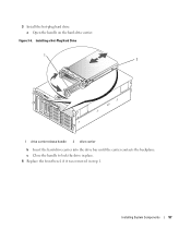
a Open the handle on the hard-drive carrier. Installing System Components 57 Figure 3-6. Installing a Hot-Plug Hard Drive 1 2 1 drive carrier release handle 2 drive carrier b Insert the hard-drive carrier into the drive bay until the carrier contacts the backplane. c Close the handle to lock the drive in place. 4 Replace the front bezel, if it was removed in step 1. 3 Install the hot-plug hard drive.
a Open the handle on the hard-drive carrier. Installing System Components 57 Figure 3-6. Installing a Hot-Plug Hard Drive 1 2 1 drive carrier release handle 2 drive carrier b Insert the hard-drive carrier into the drive bay until the carrier contacts the backplane. c Close the handle to lock the drive in place. 4 Replace the front bezel, if it was removed in step 1. 3 Install the hot-plug hard drive.

Hardware Owner's Manual (PDF)
Page 58
... the bottom rear screw hole on the hard-drive carrier and separate the hard drive from the carrier. Replacing a Hard-Drive Carrier Removing a Hard Drive From a Hard-Drive Carrier 1 If you are removing a SATA hard drive from a SATAu drive carrier, remove the interposer card: a Viewing the hard drive carrier from the rear, locate the release lever on the hard drive carrier. See Figure 3-7. 58 Installing System Components...
... the bottom rear screw hole on the hard-drive carrier and separate the hard drive from the carrier. Replacing a Hard-Drive Carrier Removing a Hard Drive From a Hard-Drive Carrier 1 If you are removing a SATA hard drive from a SATAu drive carrier, remove the interposer card: a Viewing the hard drive carrier from the rear, locate the release lever on the hard drive carrier. See Figure 3-7. 58 Installing System Components...


