
Processor Upgrade Installation Guide (.pdf)
Page 1
... system back panel. This document provides instructions for installing the remote access card on your Installation and Troubleshooting Guide for detailed instructions on removing or replacing components. 1 Turn off the system, including any of the system (if present). See your Product Information Guide for property damage, personal injury, or death. www...
... system back panel. This document provides instructions for installing the remote access card on your Installation and Troubleshooting Guide for detailed instructions on removing or replacing components. 1 Turn off the system, including any of the system (if present). See your Product Information Guide for property damage, personal injury, or death. www...

Information Update
Page 6
...redirection being enabled in the System Setup program (console redirection is intended for a vt100-compatible terminal. Console redirection is disabled by default). Dell™ PowerEdge™ Expandable RAID Controller (PERC) cards and the Broadcom 5721 PCI-e NIC do not support hot-plug PCI-e operation. 4 Information... only to the system's serial port. Hot-add will not be supported. • The QLogic PCI-e FC HBA will support hot-replace and hot-remove operation under the Windows Server 2003 and Windows 2000 Server and Advanced Server operating systems, or the Novell® NetWare&#...
...redirection being enabled in the System Setup program (console redirection is intended for a vt100-compatible terminal. Console redirection is disabled by default). Dell™ PowerEdge™ Expandable RAID Controller (PERC) cards and the Broadcom 5721 PCI-e NIC do not support hot-plug PCI-e operation. 4 Information... only to the system's serial port. Hot-add will not be supported. • The QLogic PCI-e FC HBA will support hot-replace and hot-remove operation under the Windows Server 2003 and Windows 2000 Server and Advanced Server operating systems, or the Novell® NetWare&#...

Information Update
Page 9
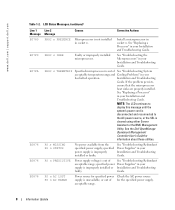
...PG n System power supply is out of acceptable range; See "Troubleshooting Redundant Power Supplies" in your Installation and Troubleshooting Guide. Replace the RAID battery. VOLT BATT CMOS Faulty system battery. VOLT RISER 5V VOLT RISER Riser card voltage is out of acceptable ...message. VOLT BATT ROMB Faulty RAID battery. See "Activating the Optional Integrated RAID Controller" in your Installation and Troubleshooting Guide. Replace the system battery. faulty system board. If the problem persists, see "Getting Help" in your Installation and Troubleshooting Guide. ...
...PG n System power supply is out of acceptable range; See "Troubleshooting Redundant Power Supplies" in your Installation and Troubleshooting Guide. Replace the RAID battery. VOLT BATT CMOS Faulty system battery. VOLT RISER 5V VOLT RISER Riser card voltage is out of acceptable ...message. VOLT BATT ROMB Faulty RAID battery. See "Activating the Optional Integrated RAID Controller" in your Installation and Troubleshooting Guide. Replace the system battery. faulty system board. If the problem persists, see "Getting Help" in your Installation and Troubleshooting Guide. ...
Information Update
Page 10
...Troubleshooting Redundant acceptable range; See the Dell OpenManage Baseboard Management Controller User's Guide for specified power Check the AC power source supply is not installed in your Installation and Troubleshooting Guide. See "Replacing a Processor" in your Installation and... cleared using either Server Assistant or the BMC Management Utility. specified power Power Supplies" in socket n. www.dell.com | support.dell.com Table 1-2. specified power supply is improperly installed or Installation and Troubleshooting faulty. LCD Status Messages (continued...
...Troubleshooting Redundant acceptable range; See the Dell OpenManage Baseboard Management Controller User's Guide for specified power Check the AC power source supply is not installed in your Installation and Troubleshooting Guide. See "Replacing a Processor" in your Installation and... cleared using either Server Assistant or the BMC Management Utility. specified power Power Supplies" in socket n. www.dell.com | support.dell.com Table 1-2. specified power supply is improperly installed or Installation and Troubleshooting faulty. LCD Status Messages (continued...

Information Update
Page 12
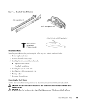
Installing the cable-management arm on the right side (when facing the back of the rack will require you install it on the left side of the system). www.dell.com | support.dell.com Installing the Cable-Management Arm Although the cable-management arm can be installed on either side of the system rack, it is recommended that you to disengage the cablemanagement arm to access the power supplies for removal or replacement. 10 Information Update
Installing the cable-management arm on the right side (when facing the back of the rack will require you install it on the left side of the system). www.dell.com | support.dell.com Installing the Cable-Management Arm Although the cable-management arm can be installed on either side of the system rack, it is recommended that you to disengage the cablemanagement arm to access the power supplies for removal or replacement. 10 Information Update

Installing the 1 x 2 SCSI Backplane
Page 5
... components inside the computer, and protecting against electrostatic discharge. Before you install the backplane, update the BIOS to the latest version. See the Dell Support website at support.dell.com for the latest BIOS version for instructions on its side, as shown in Figure 1-1. 4 Open the system. Before You Begin NOTICE: Before....book Page 3 Tuesday, July 6, 2004 4:33 PM This document provides instructions for installing a 1 x 2 module kit to add support for up all data on removing or replacing components.
... components inside the computer, and protecting against electrostatic discharge. Before you install the backplane, update the BIOS to the latest version. See the Dell Support website at support.dell.com for the latest BIOS version for instructions on its side, as shown in Figure 1-1. 4 Open the system. Before You Begin NOTICE: Before....book Page 3 Tuesday, July 6, 2004 4:33 PM This document provides instructions for installing a 1 x 2 module kit to add support for up all data on removing or replacing components.
Installing the 1 x 2 SCSI Backplane
Page 10
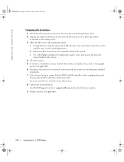
www.dell.com | support.dell.com F6590bk0.book Page 8 Tuesday, July 6, 2004 4:33 PM Completing the Installation 1 Check all cable connections that may also need to verify the correct boot ... system on the system cover or block the airflow of the system. See the Dell Support website at support.dell.com for more information. 8 Update the system firmware. See your system User's Guide for the latest firmware updates. 9 Replace the bezel (if applicable). 1-8 Installing the 1 x 2 SCSI Module You may have a standalone system, reinstall...
www.dell.com | support.dell.com F6590bk0.book Page 8 Tuesday, July 6, 2004 4:33 PM Completing the Installation 1 Check all cable connections that may also need to verify the correct boot ... system on the system cover or block the airflow of the system. See the Dell Support website at support.dell.com for more information. 8 Update the system firmware. See your system User's Guide for the latest firmware updates. 9 Replace the bezel (if applicable). 1-8 Installing the 1 x 2 SCSI Module You may have a standalone system, reinstall...
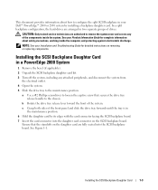
Installing the SCSI Backplane Daughter Card
Page 5
... the daughter card connector on removing or replacing components. NOTE: See your Product Information Guide for detailed instructions on the SCSI backplane board. This document provides information about safety precautions, working inside the system. Installing the SCSI Backplane Daughter Card in your Dell™ PowerEdge™ 2800 or 2850 system by its edges with...
... the daughter card connector on removing or replacing components. NOTE: See your Product Information Guide for detailed instructions on the SCSI backplane board. This document provides information about safety precautions, working inside the system. Installing the SCSI Backplane Daughter Card in your Dell™ PowerEdge™ 2800 or 2850 system by its edges with...

Installing the SCSI Backplane Daughter Card
Page 6
www.dell.com | support.dell.com Figure 1-1. c Use a #2 Phillips screwdriver to tighten the captive screw that secures the drive tray release handle to the chassis. 10 Close the system. 11 ... SCSI backplane. This channel controls drives 4, 5, 8, and 9. 9 Slide the drive tray back into the operating position. See your system's User's Guide for more information. 13 Replace the bezel (if applicable). 1-4 Installing the SCSI Backplane Daughter Card
www.dell.com | support.dell.com Figure 1-1. c Use a #2 Phillips screwdriver to tighten the captive screw that secures the drive tray release handle to the chassis. 10 Close the system. 11 ... SCSI backplane. This channel controls drives 4, 5, 8, and 9. 9 Slide the drive tray back into the operating position. See your system's User's Guide for more information. 13 Replace the bezel (if applicable). 1-4 Installing the SCSI Backplane Daughter Card

Installing the SCSI Backplane Daughter Card
Page 9
... activate the 2/4 split backplane configuration. This channel controls drives 2 through 5. NOTE: If a cable is configured correctly. See your system's User's Guide for more information. 13 Replace the bezel (if applicable). Installing the SCSI Backplane Daughter Card 1-7 b Connect SCSI channel B (channel 1) on the controller card to connector SCSIA on the SCSI backplane...
... activate the 2/4 split backplane configuration. This channel controls drives 2 through 5. NOTE: If a cable is configured correctly. See your system's User's Guide for more information. 13 Replace the bezel (if applicable). Installing the SCSI Backplane Daughter Card 1-7 b Connect SCSI channel B (channel 1) on the controller card to connector SCSIA on the SCSI backplane...
Processor Upgrade Installation Guide
Page 5
See www.dell.com and support.dell.com for information on processor availability and upgrade options for the primary processor on the system board. NOTICE: The processor and heat sink can add secondary processors or replace processors in your system. It is recommended that is ...chassis is labeled with a "II," your Installation and Troubleshooting Guide for detailed instructions on the Dell Support website at support.dell.com, and upgrade the BIOS if necessary. Adding or Replacing a Processor NOTICE: The secondary processor must be removed from the electrical outlet. 3 Open the...
See www.dell.com and support.dell.com for information on processor availability and upgrade options for the primary processor on the system board. NOTICE: The processor and heat sink can add secondary processors or replace processors in your system. It is recommended that is ...chassis is labeled with a "II," your Installation and Troubleshooting Guide for detailed instructions on the Dell Support website at support.dell.com, and upgrade the BIOS if necessary. Adding or Replacing a Processor NOTICE: The secondary processor must be removed from the electrical outlet. 3 Open the...
Processor Upgrade Installation Guide
Page 9
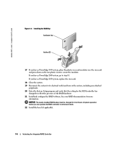
...that the processor information matches the new system configuration. Processor Upgrade Installation Guide 7 11 Reinstall the center fan bracket or replace the memory module shroud (if applicable). 12 If you have added an additional processor, install the processor cooling fan(s) for ... Close the system. 15 Reconnect your Installation and Troubleshooting Guide for instructions about running the diagnostics and troubleshooting processor problems. 18 Replace the bezel (if applicable). As the system boots, it detects the presence of the new processor and automatically changes the system...
...that the processor information matches the new system configuration. Processor Upgrade Installation Guide 7 11 Reinstall the center fan bracket or replace the memory module shroud (if applicable). 12 If you have added an additional processor, install the processor cooling fan(s) for ... Close the system. 15 Reconnect your Installation and Troubleshooting Guide for instructions about running the diagnostics and troubleshooting processor problems. 18 Replace the bezel (if applicable). As the system boots, it detects the presence of the new processor and automatically changes the system...
Activating the Integrated RAID Controller
Page 5
CAUTION: Only trained service technicians are authorized to activate the integrated RAID controller on Dell™ PowerEdge™ 1850, 2800, and 2850 systems. Your upgrade kit includes a RAID controller memory module, RAID hardware key, RAID battery, and RAID software. This document explains...card, you perform the following procedures, ensure that is not present on the riser card. See your PowerEdge 1850 riser card supports the RAID option. To use the RAID option, replace the standard riser card with the optional ROMB PCI-X or PCI-Express riser card. Before you have ...
CAUTION: Only trained service technicians are authorized to activate the integrated RAID controller on Dell™ PowerEdge™ 1850, 2800, and 2850 systems. Your upgrade kit includes a RAID controller memory module, RAID hardware key, RAID battery, and RAID software. This document explains...card, you perform the following procedures, ensure that is not present on the riser card. See your PowerEdge 1850 riser card supports the RAID option. To use the RAID option, replace the standard riser card with the optional ROMB PCI-X or PCI-Express riser card. Before you have ...
Activating the Integrated RAID Controller
Page 7
...13. 12 If you have a PowerEdge 2800 system, remove the memory cooling shroud by lifting the release latch and sliding the shroud forward. Activating the Integrated RAID Controller 1-5 See Figure 1-3. 14 If you have a PowerEdge 2800 or 2850 system, replace or lower the memory cooling shroud.... 15 If you have a PowerEdge 1850 system, install the RAID battery into the RAID battery holder. c Install the RAID battery...
...13. 12 If you have a PowerEdge 2800 system, remove the memory cooling shroud by lifting the release latch and sliding the shroud forward. Activating the Integrated RAID Controller 1-5 See Figure 1-3. 14 If you have a PowerEdge 2800 or 2850 system, replace or lower the memory cooling shroud.... 15 If you have a PowerEdge 1850 system, install the RAID battery into the RAID battery holder. c Install the RAID battery...
Activating the Integrated RAID Controller
Page 8
....dell.com | support.dell.com Figure 1-3. Installing the RAID Key hardware key latches (2) 17 If you have a PowerEdge 2850 system, replace the riser card. 18 Close the system. 19 Reconnect the system to its electrical outlet and turn on the two plastic rivets to reflect the presence of system operation before you have a PowerEdge 2800 system...
....dell.com | support.dell.com Figure 1-3. Installing the RAID Key hardware key latches (2) 17 If you have a PowerEdge 2850 system, replace the riser card. 18 Close the system. 19 Reconnect the system to its electrical outlet and turn on the two plastic rivets to reflect the presence of system operation before you have a PowerEdge 2800 system...

Rack- to-Tower Conversion Guide
Page 6
... Bezel 31 4 Contents Figure 1-14. Figure 1-17. Figure 1-3. Figure 1-19. Y1001bk0.book Page 4 Thursday, July 8, 2004 4:32 PM Installing the Metal Feet and Bezel 29 Replacing the Rack Doors 31 Figures Figure 1-1. Figure 1-7. Figure 1-11. Figure 1-16. Figure 1-2.
... Bezel 31 4 Contents Figure 1-14. Figure 1-17. Figure 1-3. Figure 1-19. Y1001bk0.book Page 4 Thursday, July 8, 2004 4:32 PM Installing the Metal Feet and Bezel 29 Replacing the Rack Doors 31 Figures Figure 1-1. Figure 1-7. Figure 1-11. Figure 1-16. Figure 1-2.

Rack- to-Tower Conversion Guide
Page 22
... panel assembly and rack front panel • Installing the tower front panel and tower control panel assembly • Installing the metal feet and bezel • Replacing the rack doors Removing the Rack Doors You must remove the doors from the rack cabinet to provide access to the interior of the rack... screwdriver • 1/4-inch nut driver • Torx T-10 driver (for removing doors in two phases. Y1001bk0.book Page 20 Thursday, July 8, 2004 4:32 PM www.dell.com | support.dell.com Before You Begin Before you begin removing your rack cabinet.
... panel assembly and rack front panel • Installing the tower front panel and tower control panel assembly • Installing the metal feet and bezel • Replacing the rack doors Removing the Rack Doors You must remove the doors from the rack cabinet to provide access to the interior of the rack... screwdriver • 1/4-inch nut driver • Torx T-10 driver (for removing doors in two phases. Y1001bk0.book Page 20 Thursday, July 8, 2004 4:32 PM www.dell.com | support.dell.com Before You Begin Before you begin removing your rack cabinet.

Rack- to-Tower Conversion Guide
Page 33
Tower-to-Rack and Rack-to-Tower Conversion Guide 31 Y1001bk0.book Page 31 Thursday, July 8, 2004 4:32 PM Figure 1-19. Installing the Tower Bezel release latch keylock bezel Replacing the Rack Doors See the procedures for replacing doors in the documentation provided with your rack cabinet.
Tower-to-Rack and Rack-to-Tower Conversion Guide 31 Y1001bk0.book Page 31 Thursday, July 8, 2004 4:32 PM Figure 1-19. Installing the Tower Bezel release latch keylock bezel Replacing the Rack Doors See the procedures for replacing doors in the documentation provided with your rack cabinet.

Rack Installation Guide
Page 5
... Installing the RapidRails Slide Assemblies 1-12 Installing the VersaRails Slide Assemblies 1-13 Installing the System in the Rack 1-14 Installing the Cable-Management Arm 1-16 Replacing the Rack Doors 1-20 Two-Post Rack Installation 1-21 Two-Post Rack Installation Tasks 1-21 Recommended Tools and Supplies 1-21 Rack Kit Contents 1-22 Marking...
... Installing the RapidRails Slide Assemblies 1-12 Installing the VersaRails Slide Assemblies 1-13 Installing the System in the Rack 1-14 Installing the Cable-Management Arm 1-16 Replacing the Rack Doors 1-20 Two-Post Rack Installation 1-21 Two-Post Rack Installation Tasks 1-21 Recommended Tools and Supplies 1-21 Rack Kit Contents 1-22 Marking...
Rack Installation Guide
Page 11
... the slide assemblies in the rack: • RapidRails installation • VersaRails installation 4 Installing the system in the rack 5 Installing the cable-management arm 6 Routing cables 7 Replacing the rack doors Removing the Rack Doors See the procedures for removing doors in the documentation provided with your rack cabinet.
... the slide assemblies in the rack: • RapidRails installation • VersaRails installation 4 Installing the system in the rack 5 Installing the cable-management arm 6 Routing cables 7 Replacing the rack doors Removing the Rack Doors See the procedures for removing doors in the documentation provided with your rack cabinet.


