Information Update
Page 11
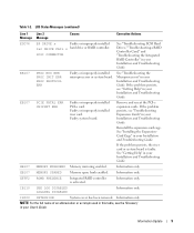
SCSI CONNECTOR See "Troubleshooting SCSI Hard Drives," "Troubleshooting a RAID Controller Card," and "Troubleshooting the Integrated RAID Controller" in your Installation and Troubleshooting Guide. If the problem persists, see the... card or system board is activated. LCD Status Messages (continued) Line 1 Line 2 Message Message Causes Corrective Actions E0D76 BP DRIVE n Faulty or improperly installed 1x2 DRIVE FAIL n hard drive or RAID controller. Information only. EFFF2 ROMB PRESENCE Integrated RAID controller is faulty. Information only NOTE: For the full name of...
SCSI CONNECTOR See "Troubleshooting SCSI Hard Drives," "Troubleshooting a RAID Controller Card," and "Troubleshooting the Integrated RAID Controller" in your Installation and Troubleshooting Guide. If the problem persists, see the... card or system board is activated. LCD Status Messages (continued) Line 1 Line 2 Message Message Causes Corrective Actions E0D76 BP DRIVE n Faulty or improperly installed 1x2 DRIVE FAIL n hard drive or RAID controller. Information only. EFFF2 ROMB PRESENCE Integrated RAID controller is faulty. Information only NOTE: For the full name of...

Information Update
Page 50
www.dell.com | support.dell.com 表 1-2 LCD 1 行目の 2 原因 対応処置 E0876 PS n MISSING PS n STATUS Troubleshooting Redundant Power Supplies E0876 PS n PREDICTIVE Troubleshooting Redundant Power Supplies E0876 PS n AC LOST PS n AC RANGE AC AC AC E0D76 BP DRIVE n 1x2 DRIVE FAIL n SCSI CONNECTOR RAID Troubleshooting SCSI Hard Drives」...
www.dell.com | support.dell.com 表 1-2 LCD 1 行目の 2 原因 対応処置 E0876 PS n MISSING PS n STATUS Troubleshooting Redundant Power Supplies E0876 PS n PREDICTIVE Troubleshooting Redundant Power Supplies E0876 PS n AC LOST PS n AC RANGE AC AC AC E0D76 BP DRIVE n 1x2 DRIVE FAIL n SCSI CONNECTOR RAID Troubleshooting SCSI Hard Drives」...

Installing the 1 x 2 SCSI Backplane
Page 5
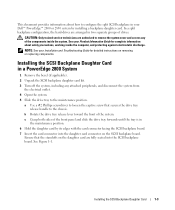
See the Dell Support website at support.dell.com for the latest BIOS version for your Product Information Guide for complete information about safety precautions, working inside the system. Before you have a standalone ... lay the system on its side, as shown in Figure 1-1. 4 Open the system. NOTICE: To avoid data loss, back up to two additional 1-inch SCSI hard drives in a rack, go to step 4. See your Installation and Troubleshooting Guide for detailed instructions on using the System Setup program. 2 Update the BIOS. See your...
See the Dell Support website at support.dell.com for the latest BIOS version for your Product Information Guide for complete information about safety precautions, working inside the system. Before you have a standalone ... lay the system on its side, as shown in Figure 1-1. 4 Open the system. NOTICE: To avoid data loss, back up to two additional 1-inch SCSI hard drives in a rack, go to step 4. See your Installation and Troubleshooting Guide for detailed instructions on using the System Setup program. 2 Update the BIOS. See your...

Installing the 1 x 2 SCSI Backplane
Page 9
... cable routing slot 1. F6590bk0.book Page 7 Tuesday, July 6, 2004 4:33 PM 2 Connect the SCSI connector on the riser card. See Figure 1-4. See Figure 1-3. 3 Install the hard drives into the 1 x 2 module. See Figure 1-4. If your 1 x 2 module connects to the onboard riser card: a Connect the SCSI connector on the 1 x 2 backplane to SCSI channel A on...
... cable routing slot 1. F6590bk0.book Page 7 Tuesday, July 6, 2004 4:33 PM 2 Connect the SCSI connector on the riser card. See Figure 1-4. See Figure 1-3. 3 Install the hard drives into the 1 x 2 module. See Figure 1-4. If your 1 x 2 module connects to the onboard riser card: a Connect the SCSI connector on the 1 x 2 backplane to SCSI channel A on...
Installing the SCSI Backplane Daughter Card
Page 5
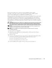
...a split backplane configuration, the hard-drives are authorized to remove the system cover and access any attached peripherals, and disconnect the system from the electrical outlet. 4 Open the system. 5 Slide the drive tray to configure the split SCSI backplane in a PowerEdge 2800 System 1 Remove the bezel ... the chassis. NOTE: See your Dell™ PowerEdge™ 2800 or 2850 system by its edges with the card connector facing the SCSI backplane board. 7 Insert the card connector into the SCSI backplane board. Ensure that secures the drive tray release handle to loosen the ...
...a split backplane configuration, the hard-drives are authorized to remove the system cover and access any attached peripherals, and disconnect the system from the electrical outlet. 4 Open the system. 5 Slide the drive tray to configure the split SCSI backplane in a PowerEdge 2800 System 1 Remove the bezel ... the chassis. NOTE: See your Dell™ PowerEdge™ 2800 or 2850 system by its edges with the card connector facing the SCSI backplane board. 7 Insert the card connector into the SCSI backplane board. Ensure that secures the drive tray release handle to loosen the ...
Activating the Integrated RAID Controller
Page 5
...Troubleshooting Guide to step 5. NOTICE: To avoid possible data loss, back up all data on the hard drives before changing the mode of operation of the riser card. If you have a PowerEdge 1850 system, remove the riser card insulator by lifting the two blue rivets at each end of ...system, including any of riser card that is not present on the riser card, you have a PowerEdge 2850, remove the riser card. 5 Locate the RAID memory module connector on Dell™ PowerEdge™ 1850, 2800, and 2850 systems. Your upgrade kit includes a RAID controller memory module, RAID hardware key, RAID ...
...Troubleshooting Guide to step 5. NOTICE: To avoid possible data loss, back up all data on the hard drives before changing the mode of operation of the riser card. If you have a PowerEdge 1850 system, remove the riser card insulator by lifting the two blue rivets at each end of ...system, including any of riser card that is not present on the riser card, you have a PowerEdge 2850, remove the riser card. 5 Locate the RAID memory module connector on Dell™ PowerEdge™ 1850, 2800, and 2850 systems. Your upgrade kit includes a RAID controller memory module, RAID hardware key, RAID ...

Rack- to-Tower Conversion Guide
Page 14
... grasping both sides of the system. Removing and Installing the Cover cover www.dell.com | support.dell.com thumbscrews (2) Removing the Control Panel Assembly and Tower Front Panel 1 Slide the drive tray to -Tower Conversion Guide f Remove the hard drives, any optical drives, and devices installed in the media bay from the media bay devices. a Using...
... grasping both sides of the system. Removing and Installing the Cover cover www.dell.com | support.dell.com thumbscrews (2) Removing the Control Panel Assembly and Tower Front Panel 1 Slide the drive tray to -Tower Conversion Guide f Remove the hard drives, any optical drives, and devices installed in the media bay from the media bay devices. a Using...

Rack- to-Tower Conversion Guide
Page 17
.... h Slide the control panel assembly's cable through the hole in Figure 1-5. 6 Reinstall the hard drives, any optical drives, and devices are reinstalled into the same positions that the hard drives, any optical drives, and devices installed in the media bay in the drive tray. See Figure 1-6. 4 Connect the control panel assembly cable to the rack carrier. NOTE...
.... h Slide the control panel assembly's cable through the hole in Figure 1-5. 6 Reinstall the hard drives, any optical drives, and devices are reinstalled into the same positions that the hard drives, any optical drives, and devices installed in the media bay in the drive tray. See Figure 1-6. 4 Connect the control panel assembly cable to the rack carrier. NOTE...

Rack- to-Tower Conversion Guide
Page 28
... release handle to the maintenance position. Removing the System Cover system cover www.dell.com | support.dell.com thumbscrews (2) Removing the Control Panel Assembly and Rack Front Panel 1 Slide the drive tray to the chassis. f Remove the hard drives, any optical drives, and devices installed in the media bay from the media bay devices. See Figure...
... release handle to the maintenance position. Removing the System Cover system cover www.dell.com | support.dell.com thumbscrews (2) Removing the Control Panel Assembly and Rack Front Panel 1 Slide the drive tray to the chassis. f Remove the hard drives, any optical drives, and devices installed in the media bay from the media bay devices. See Figure...

Rack- to-Tower Conversion Guide
Page 31
...I /O board on the control panel assembly with your kit. k While holding the control panel assembly in Figure 1-16. 6 Reinstall the hard drives, any optical drives, and devices are reinstalled into the same positions that the system is very fragile. See Figure 1-18. a Using a #2 Phillips screwdriver,...Metal Feet and Bezel 1 Position the system on the tower carrier. g Remove the protective covering from . NOTE: Ensure that the hard drives, any optical drives, and devices installed in the media bay in the operational position. Tower-to-Rack and Rack-to the rack carrier. d Using a...
...I /O board on the control panel assembly with your kit. k While holding the control panel assembly in Figure 1-16. 6 Reinstall the hard drives, any optical drives, and devices are reinstalled into the same positions that the system is very fragile. See Figure 1-18. a Using a #2 Phillips screwdriver,...Metal Feet and Bezel 1 Position the system on the tower carrier. g Remove the protective covering from . NOTE: Ensure that the hard drives, any optical drives, and devices installed in the media bay in the operational position. Tower-to-Rack and Rack-to the rack carrier. d Using a...


