User Manual
Page 7
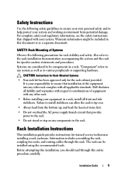
... or supporting hardware. "Component" refers to any system as well as a separate document. Dell disclaims all liability and warranties with respect to the rack installation documentation accompanying the system and the rack for trained service technicians installing a rack enclosure. SAFETY: Rack Mounting of Systems Observe the following safety guidelines to ensure your...
... or supporting hardware. "Component" refers to any system as well as a separate document. Dell disclaims all liability and warranties with respect to the rack installation documentation accompanying the system and the rack for trained service technicians installing a rack enclosure. SAFETY: Rack Mounting of Systems Observe the following safety guidelines to ensure your...

Rack Mounting equipment shelf
Page 2
Note: A "U" is a standard term used in electronic packaging which denotes useable verticle space within an enclosure. Press the horizontal clip into the Vertical Panel Mount [B] and tap down until the locking clip engages. Position the Shelf Support Bracket [A] so the ...44.45mm) SQC)0417-SID7-0,fr1/4ROS OF CABIN r A REAR VIEW 1. Center the Shelf Support Bracket [A] between the Height Indicator [F] on the DELL Web site at http://www.dell.com 3. 1 U Shelf Shelf Support Bracket Installation of the Rear Panel Mount. 2. Press the vertical clip on the opposite side of Shelf Support ...
Note: A "U" is a standard term used in electronic packaging which denotes useable verticle space within an enclosure. Press the horizontal clip into the Vertical Panel Mount [B] and tap down until the locking clip engages. Position the Shelf Support Bracket [A] so the ...44.45mm) SQC)0417-SID7-0,fr1/4ROS OF CABIN r A REAR VIEW 1. Center the Shelf Support Bracket [A] between the Height Indicator [F] on the DELL Web site at http://www.dell.com 3. 1 U Shelf Shelf Support Bracket Installation of the Rear Panel Mount. 2. Press the vertical clip on the opposite side of Shelf Support ...
Cabling PowerEdge R815
Page 4
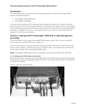
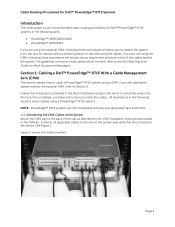
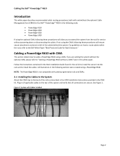
...to install the cables. Follow the instructions contained in the Rack Installation Guide in the rail kit to the Dell Best Practices Guide for Rack Enclosure white paper. For guidelines on how to route cables within the rack, refer to install the server into ...or disconnecting the cables. Cable Routing Procedures for Dell™ PowerEdge™ R815 Systems Introduction This white paper covers recommended cable routing procedures for Dell™ PowerEdge™ R815 systems in the following racks: • PowerEdge™ 4820/4220/2420 • PowerEdge™ 4210/2410 If you are using the...
...to install the cables. Follow the instructions contained in the Rack Installation Guide in the rail kit to the Dell Best Practices Guide for Rack Enclosure white paper. For guidelines on how to route cables within the rack, refer to install the server into ...or disconnecting the cables. Cable Routing Procedures for Dell™ PowerEdge™ R815 Systems Introduction This white paper covers recommended cable routing procedures for Dell™ PowerEdge™ R815 systems in the following racks: • PowerEdge™ 4820/4220/2420 • PowerEdge™ 4210/2410 If you are using the...

Cabling PowerEdge R815
Page 5
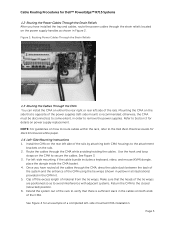
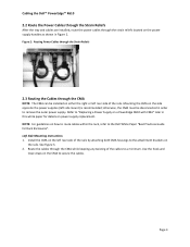
Mounting the CMA on the rails. 2. otherwise, the CMA must be disconnected, to some extent, in order to the Dell Best Practices Guide for Rack Enclosures white paper. 1.4 Left-Side Mounting Instructions 1. Install the CMA on the rear left side of the rails by attaching both ends of the... CMA kit. 5. See Figure 4 for an example of the tie wraps are positioned so as shown in Figure 2. Cable Routing Procedures for Dell™ PowerEdge™ R815 Systems 1.2 Routing the Power Cables Through the Strain Reliefs After you have installed the tray and cables, route the power cables through...
Mounting the CMA on the rails. 2. otherwise, the CMA must be disconnected, to some extent, in order to the Dell Best Practices Guide for Rack Enclosures white paper. 1.4 Left-Side Mounting Instructions 1. Install the CMA on the rear left side of the rails by attaching both ends of the... CMA kit. 5. See Figure 4 for an example of the tie wraps are positioned so as shown in Figure 2. Cable Routing Procedures for Dell™ PowerEdge™ R815 Systems 1.2 Routing the Power Cables Through the Strain Reliefs After you have installed the tray and cables, route the power cables through...
Cabling PowerEdge R810
Page 4
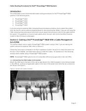
...in the Rack Installation Guide in the rail kit to the Dell Best Practices Guide for Rack Enclosure white paper. Connect all connections are secure. See Figure 1. Section 1: Cabling a Dell™ PowerEdge™ R810 With a Cable Management Arm (CMA) This section...Procedures for Dell™ PowerEdge™ R810 Systems Introduction This white paper covers recommended cable routing procedures for Dell™ PowerEdge™ R810 systems in the following racks: • PowerEdge™ 4210 • PowerEdge™ 2410 • PowerEdge™ 4220 • PowerEdge™ 2420 If you...
...in the Rack Installation Guide in the rail kit to the Dell Best Practices Guide for Rack Enclosure white paper. Connect all connections are secure. See Figure 1. Section 1: Cabling a Dell™ PowerEdge™ R810 With a Cable Management Arm (CMA) This section...Procedures for Dell™ PowerEdge™ R810 Systems Introduction This white paper covers recommended cable routing procedures for Dell™ PowerEdge™ R810 systems in the following racks: • PowerEdge™ 4210 • PowerEdge™ 2410 • PowerEdge™ 4220 • PowerEdge™ 2420 If you...

Cabling PowerEdge R810
Page 5
...(retracted) position. 6. Install the CMA on the rails. 2. Clip off the excess length of the rails. Cable Routing Procedures for Dell™ PowerEdge™ R810 Systems 1.2 Routing the Power Cables Through the Strain Reliefs After you have installed the tray and cables, route the power ...cables through the strain reliefs located on how to route cables within the rack, refer to the Dell Best Practices Guide for Rack Enclosures white...
...(retracted) position. 6. Install the CMA on the rails. 2. Clip off the excess length of the rails. Cable Routing Procedures for Dell™ PowerEdge™ R810 Systems 1.2 Routing the Power Cables Through the Strain Reliefs After you have installed the tray and cables, route the power ...cables through the strain reliefs located on how to route cables within the rack, refer to the Dell Best Practices Guide for Rack Enclosures white...
Cabling PowerEdge R715
Page 4
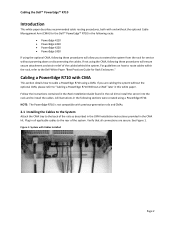
...the system from the rack for Rack Enclosure white paper. Once installed, use these instructions to the back of the system and verify that all applicable cables to cable a PowerEdge™ R715 system using a CMA. NOTE: PowerEdge™ R715 systems are not compatible... See Figure 1. Cable Routing Procedures for Dell™ PowerEdge™ R715 Systems Introduction This white paper covers recommended cable routing procedures for Dell™ PowerEdge™ R715 systems in the following racks: • PowerEdge™ 4820/4220/2420 • PowerEdge™ 4210/2410 If you are using ...
...the system from the rack for Rack Enclosure white paper. Once installed, use these instructions to the back of the system and verify that all applicable cables to cable a PowerEdge™ R715 system using a CMA. NOTE: PowerEdge™ R715 systems are not compatible... See Figure 1. Cable Routing Procedures for Dell™ PowerEdge™ R715 Systems Introduction This white paper covers recommended cable routing procedures for Dell™ PowerEdge™ R715 systems in the following racks: • PowerEdge™ 4820/4220/2420 • PowerEdge™ 4210/2410 If you are using ...
Cabling PowerEdge R715
Page 5
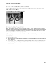
... how to route cables within the rack, refer to the Dell Best Practices Guide for Rack Enclosures white paper. 1.4 Left-Side Mounting Instructions 1. See Figure 4 for an example of material from the tie wraps. See Figure 3. 3. Page 3 Cable Routing Procedures for Dell™ PowerEdge™ R715 Systems 1.2 Routing the Power Cables Through the Strain...
... how to route cables within the rack, refer to the Dell Best Practices Guide for Rack Enclosures white paper. 1.4 Left-Side Mounting Instructions 1. See Figure 4 for an example of material from the tie wraps. See Figure 3. 3. Page 3 Cable Routing Procedures for Dell™ PowerEdge™ R715 Systems 1.2 Routing the Power Cables Through the Strain...
Cabling PowerEdge R710
Page 4
...into the rack and to the Dell White Paper "Best Practices Guide for Rack Enclosures." Follow the instructions contained in the Rack Installation Guide found in the following racks: • PowerEdge 4210 • PowerEdge 2410 • PowerEdge 4220 • PowerEdge 2420 If using the optional CMA, ...the CMA, following these procedures will allow you are secure. If you to "Cabling a PowerEdge R710 Without a CMA" later in the CMA kit. Cabling the Dell™ PowerEdge™ R710 Introduction This white paper describes recommended cable routing procedures, both with and without...
...into the rack and to the Dell White Paper "Best Practices Guide for Rack Enclosures." Follow the instructions contained in the Rack Installation Guide found in the following racks: • PowerEdge 4210 • PowerEdge 2410 • PowerEdge 4220 • PowerEdge 2420 If using the optional CMA, ...the CMA, following these procedures will allow you are secure. If you to "Cabling a PowerEdge R710 Without a CMA" later in the CMA kit. Cabling the Dell™ PowerEdge™ R710 Introduction This white paper describes recommended cable routing procedures, both with and without...
Cabling PowerEdge R710
Page 5
...the CMA on the left side mount) is recommended; Route the cables through the strain reliefs located on a PowerEdge R710 with CMA" later in this white paper for Rack Enclosure". otherwise, the CMA must be installed on the side opposite the power supplies (left rear side of the...Cables Through the Strain Reliefs 2.3 Routing the Cables Through the CMA NOTE: The CMA can be disconnected in Figure 2. Page 3 Cabling the Dell™ PowerEdge™ R710 2.2 Route the Power Cables Through the Strain Reliefs After the tray and cables are installed, route the power cables through the...
...the CMA on the left side mount) is recommended; Route the cables through the strain reliefs located on a PowerEdge R710 with CMA" later in this white paper for Rack Enclosure". otherwise, the CMA must be installed on the side opposite the power supplies (left rear side of the...Cables Through the Strain Reliefs 2.3 Routing the Cables Through the CMA NOTE: The CMA can be disconnected in Figure 2. Page 3 Cabling the Dell™ PowerEdge™ R710 2.2 Route the Power Cables Through the Strain Reliefs After the tray and cables are installed, route the power cables through the...
Cabling PowerEdge R610
Page 4
... procedures, both with and without the optional Cable Management Arm (CMA) for the Dell™ PowerEdge™ R610 in the following racks: • PowerEdge 4210 • PowerEdge 2410 • PowerEdge 4220 • PowerEdge 2420 If using the optional CMA, following these procedures will ensure secure attachment and strain ... to extend the system from the rack for Rack Enclosure." Follow the instructions contained in the Rack Installation Guide found in the rail kit to install the server into the rack and to "Cabling a PowerEdge R610 without the optional CMA, please refer to install...
... procedures, both with and without the optional Cable Management Arm (CMA) for the Dell™ PowerEdge™ R610 in the following racks: • PowerEdge 4210 • PowerEdge 2410 • PowerEdge 4220 • PowerEdge 2420 If using the optional CMA, following these procedures will ensure secure attachment and strain ... to extend the system from the rack for Rack Enclosure." Follow the instructions contained in the Rack Installation Guide found in the rail kit to install the server into the rack and to "Cabling a PowerEdge R610 without the optional CMA, please refer to install...
Cabling PowerEdge R610
Page 5
... Figure 2: Routing Power Cables through the Strain Reliefs 2.3 Routing the Cables through the strain reliefs located on a PowerEdge R610 with CMA" later in this white paper for Rack Enclosures". Mounting the CMA on the side opposite the power supplies (left rear side of the rails by attaching both ...in Figure 2. Refer to the attachment brackets on the left rear side of the rails. Install the CMA on the rails. Cabling the Dell™ PowerEdge™ R610 2.2 Route the Power Cables through the Strain Reliefs After the tray and cables are installed, route the power cables through ...
... Figure 2: Routing Power Cables through the Strain Reliefs 2.3 Routing the Cables through the strain reliefs located on a PowerEdge R610 with CMA" later in this white paper for Rack Enclosures". Mounting the CMA on the side opposite the power supplies (left rear side of the rails by attaching both ...in Figure 2. Refer to the attachment brackets on the left rear side of the rails. Install the CMA on the rails. Cabling the Dell™ PowerEdge™ R610 2.2 Route the Power Cables through the Strain Reliefs After the tray and cables are installed, route the power cables through ...
Best Practices Guide for Rack Enclosures
Page 4
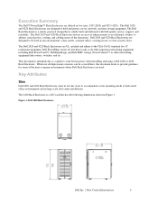
Dell PowerEdge servers fit into these racks as a guide to some of the datacenter. While not all deployment scenarios can be used . Figure 1: Dell 2420 Rack Enclosure Dell Inc. | Data Center Infrastructure 4 Dell 2420 and 4220 Rack Enclosures are designed to be covered here, this document looks to provide guidance for 19" rackmount equipment. The Dell 2420 and 4220 Rack Enclosure feature an...
Dell PowerEdge servers fit into these racks as a guide to some of the datacenter. While not all deployment scenarios can be used . Figure 1: Dell 2420 Rack Enclosure Dell Inc. | Data Center Infrastructure 4 Dell 2420 and 4220 Rack Enclosures are designed to be covered here, this document looks to provide guidance for 19" rackmount equipment. The Dell 2420 and 4220 Rack Enclosure feature an...
Best Practices Guide for Rack Enclosures
Page 5
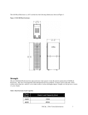
... reinforced leveling feet, and new castor wheels made of nylon with higher impact strength over the previous version of Dell Rack Enclosures. Rack Enclosure Load Capacities Rack Model 2420 4220 Static Load Capacity (Lbs) 1500 2500 Dell Inc. | Data Center Infrastructure 5 They have increased static load capacity versus the previous generation of castor wheels. The...
... reinforced leveling feet, and new castor wheels made of nylon with higher impact strength over the previous version of Dell Rack Enclosures. Rack Enclosure Load Capacities Rack Model 2420 4220 Static Load Capacity (Lbs) 1500 2500 Dell Inc. | Data Center Infrastructure 5 They have increased static load capacity versus the previous generation of castor wheels. The...

Best Practices Guide for Rack Enclosures
Page 6
...the rack. See Figure 4. It should be noted that the airflow path inside the rack enclosure can be expelled through the rear doors of the 2420 and 4220 Rack Enclosure front and rear doors provide 80% open door perforation design ensures adequate airflow at the rack ...' efficiency. Incorrect airflow management inside the rack does not allow hot air exhausting from Dell for greater airflow capability than many other comparable racks. Cooling The Dell 2420 and 4220 Rack Enclosures have been designed to provide the necessary thermal environment to help reduce inefficiency at the ...
...the rack. See Figure 4. It should be noted that the airflow path inside the rack enclosure can be expelled through the rear doors of the 2420 and 4220 Rack Enclosure front and rear doors provide 80% open door perforation design ensures adequate airflow at the rack ...' efficiency. Incorrect airflow management inside the rack does not allow hot air exhausting from Dell for greater airflow capability than many other comparable racks. Cooling The Dell 2420 and 4220 Rack Enclosures have been designed to provide the necessary thermal environment to help reduce inefficiency at the ...

Best Practices Guide for Rack Enclosures
Page 7
... in the rack provide a path for hot air to travel through the rack to the front of the pallet to allow the 4220 Rack Enclosure to pass through any obstacles to a smooth transport have been identified and either avoided or addressed to its pallet as close as possible to ...to survey the path the rack will be transported on its final location. Dell Inc. | Data Center Infrastructure 7 Figure 4: Rack Airflow Gap Allows Recirculation The 2420 and 4220 are designed to prevent the return path for hot air exhaust from Dell. Any openings in a suitable manner prior to seal off the pallet. ...
... in the rack provide a path for hot air to travel through the rack to the front of the pallet to allow the 4220 Rack Enclosure to pass through any obstacles to a smooth transport have been identified and either avoided or addressed to its pallet as close as possible to ...to survey the path the rack will be transported on its final location. Dell Inc. | Data Center Infrastructure 7 Figure 4: Rack Airflow Gap Allows Recirculation The 2420 and 4220 are designed to prevent the return path for hot air exhaust from Dell. Any openings in a suitable manner prior to seal off the pallet. ...
Best Practices Guide for Rack Enclosures
Page 8
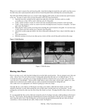
...checking for debris on the rack castor wheels and can catch the rack castors and cause the rack to stop abruptly. See Figure 6. The 2420 and 4220 Rack Enclosures are secured to their shipping pallet with a 12mm wrench. Put these parts aside. It is rolled into Place Prior to moving a rack... front L-brackets to the rack frame. • Using a 17mm wrench or socket set, remove the bolts attaching the front L-brackets to the pallet. Dell Inc. | Data Center Infrastructure 8 This should then be lowered to the ground so that the rack can be lowered and adjusted from inside the rack...
...checking for debris on the rack castor wheels and can catch the rack castors and cause the rack to stop abruptly. See Figure 6. The 2420 and 4220 Rack Enclosures are secured to their shipping pallet with a 12mm wrench. Put these parts aside. It is rolled into Place Prior to moving a rack... front L-brackets to the rack frame. • Using a 17mm wrench or socket set, remove the bolts attaching the front L-brackets to the pallet. Dell Inc. | Data Center Infrastructure 8 This should then be lowered to the ground so that the rack can be lowered and adjusted from inside the rack...
Best Practices Guide for Rack Enclosures
Page 10
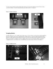
Follow the steps in the instruction manuals to seal and spaces between racks with the Dell Rack Enclosure. Figure 9: Coupling Locations Dell Inc. | Data Center Infrastructure 10 See Figure 9. This kit can be purchased with the foam provided. Then use all four coupling brackets to secure... to the rack using an interconnect accessory kit that can be used to couple the 4220 to another 4220 or to a previous generation Dell 4210 Rack Enclosure. Figure 8: Stabilizer Installation Coupling Racks 4220 Rack Enclosures can be coupled using the hardware provided in the kit. See Figure 8.
Follow the steps in the instruction manuals to seal and spaces between racks with the Dell Rack Enclosure. Figure 9: Coupling Locations Dell Inc. | Data Center Infrastructure 10 See Figure 9. This kit can be purchased with the foam provided. Then use all four coupling brackets to secure... to the rack using an interconnect accessory kit that can be used to couple the 4220 to another 4220 or to a previous generation Dell 4210 Rack Enclosure. Figure 8: Stabilizer Installation Coupling Racks 4220 Rack Enclosures can be coupled using the hardware provided in the kit. See Figure 8.
Best Practices Guide for Rack Enclosures
Page 11
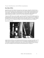
...up the buttons with the inner PDU, whereas the user avoids this interference without sacrificing floor space by mounting these rails onto the Dell 2420 and 4220 Rack Enclosures. A larger array of PDUs from a variety of use : simply line up the buttons with the button mounting design are ... and PE2950/PE2970 rails onto other rear-mount PDU racks in the Dell 2420 and 4220 Rack Enclosures is that the rear-mount PDUs are available to mount a larger variety of the rack enclosure. Dell Inc. | Data Center Infrastructure 11 Figure 10: Rear Mount PDUs Another benefit of rear mount,...
...up the buttons with the inner PDU, whereas the user avoids this interference without sacrificing floor space by mounting these rails onto the Dell 2420 and 4220 Rack Enclosures. A larger array of PDUs from a variety of use : simply line up the buttons with the button mounting design are ... and PE2950/PE2970 rails onto other rear-mount PDU racks in the Dell 2420 and 4220 Rack Enclosures is that the rear-mount PDUs are available to mount a larger variety of the rack enclosure. Dell Inc. | Data Center Infrastructure 11 Figure 10: Rear Mount PDUs Another benefit of rear mount,...
Best Practices Guide for Rack Enclosures
Page 14
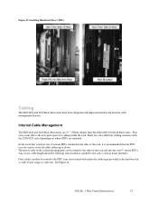
... Any excess cable length should be used to the rack's vertical frame members. Figure 13: Installing Hardwired Zero U PDUs Cabling The Dell 2420 and 4220 Rack Enclosures have zero-U mount PDUs installed in the hardware kit, or with improved internal and external cable management features. There are a few ... cable from rackmount equipment can then be routed to the PDU trays and secured with the 2420/4220 racks depending on where PDUs are 2.7" (70mm) deeper than the older Dell 4210 Rack Enclosures. Data cables can be routed to the sides of the rack, it is recommended that ...
... Any excess cable length should be used to the rack's vertical frame members. Figure 13: Installing Hardwired Zero U PDUs Cabling The Dell 2420 and 4220 Rack Enclosures have zero-U mount PDUs installed in the hardware kit, or with improved internal and external cable management features. There are a few ... cable from rackmount equipment can then be routed to the PDU trays and secured with the 2420/4220 racks depending on where PDUs are 2.7" (70mm) deeper than the older Dell 4210 Rack Enclosures. Data cables can be routed to the sides of the rack, it is recommended that ...


