
User's Guide
Page 15
... SCSI Hard-Disk Drives 7-4 Installing a SCSI Hard-Disk Drive 7-6 Removing a SCSI Hard-Disk Drive 7-7 Configuring a 2 x 2 or 2 x 3 SCSI Non-Hot-Pluggable Backplane Board 7-7 Configuring a Non-Hot-Pluggable Backplane Board as a Split Backplane . . . . 7-8 Configuring a Non-Hot-Pluggable Backplane Board as a Single Backplane . . . 7-8 Configuring the Boot Device 7-8 I/O Ports and Connectors B-1 Serial and Parallel Ports B-1 Adding an...
... SCSI Hard-Disk Drives 7-4 Installing a SCSI Hard-Disk Drive 7-6 Removing a SCSI Hard-Disk Drive 7-7 Configuring a 2 x 2 or 2 x 3 SCSI Non-Hot-Pluggable Backplane Board 7-7 Configuring a Non-Hot-Pluggable Backplane Board as a Split Backplane . . . . 7-8 Configuring a Non-Hot-Pluggable Backplane Board as a Single Backplane . . . 7-8 Configuring the Boot Device 7-8 I/O Ports and Connectors B-1 Serial and Parallel Ports B-1 Adding an...
User's Guide
Page 17
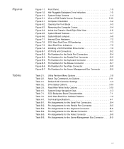
... 2-2. Table 3-2. Table B-2. Table B-4. Figure 6-2. Figure 6-4. Figure 7-4. Table 4-1. Table B-3. B-9 xix Figure B-3. Figure B-7. Table B-1. Figure 4-1. Figure 5-1. Figure 7-2. Figure B-5. Table 3-1. Table 3-3. Figure 6-1. Figure 7-1. Figure B-6. Table B-6. Figure 1-1. Front Panel 1-5 Hot-Pluggable Backplane Drive Indicators 1-5 System Setup Screens 4-4 View or Edit Details Screen (Example 5-10 Computer Orientation 6-2 Opening the Front Bezel 6-3 Removing the Computer Covers 6-4 Inside...
... 2-2. Table 3-2. Table B-2. Table B-4. Figure 6-2. Figure 6-4. Figure 7-4. Table 4-1. Table B-3. B-9 xix Figure B-3. Figure B-7. Table B-1. Figure 4-1. Figure 5-1. Figure 7-2. Figure B-5. Table 3-1. Table 3-3. Figure 6-1. Figure 7-1. Figure B-6. Table B-6. Figure 1-1. Front Panel 1-5 Hot-Pluggable Backplane Drive Indicators 1-5 System Setup Screens 4-4 View or Edit Details Screen (Example 5-10 Computer Orientation 6-2 Opening the Front Bezel 6-3 Removing the Computer Covers 6-4 Inside...

User's Guide
Page 20
.../O) controller that controls the bidirectional parallel port, two serial ports, and the diskette drive in the externally accessible front bay. The hot-pluggable 1 x 6 backplane supports hot-pluggable SCSI hard-disk drive installation and removal. microprocessor. In 800- The integrated SCSI controller resides on the system board. A ...-in flash memory on the ISA bus. This video subsystem contains 2 MB of the microprocessor for optimum performance. 1-2 Dell PowerEdge 2300 Systems User's Guide x 480-pixel resolutions, 16.7 million colors are available for performing the upgrade.
.../O) controller that controls the bidirectional parallel port, two serial ports, and the diskette drive in the externally accessible front bay. The hot-pluggable 1 x 6 backplane supports hot-pluggable SCSI hard-disk drive installation and removal. microprocessor. In 800- The integrated SCSI controller resides on the system board. A ...-in flash memory on the ISA bus. This video subsystem contains 2 MB of the microprocessor for optimum performance. 1-2 Dell PowerEdge 2300 Systems User's Guide x 480-pixel resolutions, 16.7 million colors are available for performing the upgrade.

User's Guide
Page 22
...accidentally turning off and then on the front panel lights up when data is being accessed, the green drive access indicator on again. If a hot-pluggable backplane is present in the center of the SCSI hard-disk drive bays provide the following controls and indicators are recessed into the computer... green power indicator in your system, three indicator lights adjacent to each of the power button lights up when the harddisk drive is detected. 1-4 Dell PowerEdge 2300 Systems User's Guide The green drive activity indicator (identified by allowing you to the system's power supply.
...accidentally turning off and then on the front panel lights up when data is being accessed, the green drive access indicator on again. If a hot-pluggable backplane is present in the center of the SCSI hard-disk drive bays provide the following controls and indicators are recessed into the computer... green power indicator in your system, three indicator lights adjacent to each of the power button lights up when the harddisk drive is detected. 1-4 Dell PowerEdge 2300 Systems User's Guide The green drive activity indicator (identified by allowing you to the system's power supply.

User's Guide
Page 101
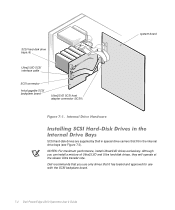
Three SCSI backplane board options are both configured by the Dell PowerEdge Expandable RAID Controller host adapter card. Figure 7-1 illustrates the internal drive bays, the 1 x 6 hot-pluggable SCSI backplane board, and the Ultra2/LVD SCSI interface cable. The connector at one end attaches ...how to install and configure small computer system interface (SCSI) hard-disk drives in the Installation and Troubleshooting Guide. Dell PowerEdge 2300 systems include a SCSI backplane board, which greatly simplifies cabling and configuration for SCSI hard-disk drives are available, as the...
Three SCSI backplane board options are both configured by the Dell PowerEdge Expandable RAID Controller host adapter card. Figure 7-1 illustrates the internal drive bays, the 1 x 6 hot-pluggable SCSI backplane board, and the Ultra2/LVD SCSI interface cable. The connector at one end attaches ...how to install and configure small computer system interface (SCSI) hard-disk drives in the Installation and Troubleshooting Guide. Dell PowerEdge 2300 systems include a SCSI backplane board, which greatly simplifies cabling and configuration for SCSI hard-disk drives are available, as the...
User's Guide
Page 102
SCSI hard-disk drive bays (6) Ultra2/LVD SCSI interface cable SCSI connector hot-pluggable SCSI backplane board Ultra2/LVD SCSI host adapter connector (SCSI1) system board SCSI hard-disk drives are supplied by Dell in the internal drive bays (see Figure 7-3). NOTES: For maximum performance, install... drives that fit in special drive carriers that it has tested and approved for use with the SCSI backplane board. 7-2 Dell PowerEdge 2300 Systems User's Guide Dell recommends that you can install a mixture of Ultra2/LVD and Ultra hard-disk drives, they will operate at the slower Ultra...
SCSI hard-disk drive bays (6) Ultra2/LVD SCSI interface cable SCSI connector hot-pluggable SCSI backplane board Ultra2/LVD SCSI host adapter connector (SCSI1) system board SCSI hard-disk drives are supplied by Dell in the internal drive bays (see Figure 7-3). NOTES: For maximum performance, install... drives that fit in special drive carriers that it has tested and approved for use with the SCSI backplane board. 7-2 Dell PowerEdge 2300 Systems User's Guide Dell recommends that you can install a mixture of Ultra2/LVD and Ultra hard-disk drives, they will operate at the slower Ultra...

User's Guide
Page 103
... before spinning. The SCSI drive must be configured as shown in Figure 7-2. SCSI ID 5 SCSI ID 0 1 x 6 hot-pluggable SCSI backplane board SCSI ID 5 SCSI ID 0 2 x 3 non-hot-pluggable SCSI backplane board SCSI ID 3 SCSI ID 0 2 x 2 non-hot-pluggable SCSI backplane board Installing SCSI Hard-Disk Drives 7-3 Set the SCSI ID on the drive.
... before spinning. The SCSI drive must be configured as shown in Figure 7-2. SCSI ID 5 SCSI ID 0 1 x 6 hot-pluggable SCSI backplane board SCSI ID 5 SCSI ID 0 2 x 3 non-hot-pluggable SCSI backplane board SCSI ID 3 SCSI ID 0 2 x 2 non-hot-pluggable SCSI backplane board Installing SCSI Hard-Disk Drives 7-3 Set the SCSI ID on the drive.

User's Guide
Page 104
...RAID Controller host adapter card to ensure that the SCSI host adapter is configured correctly to support hot-pluggable drive removal and insertion. Dell PowerEdge 2300 systems with the operating system to partition and format SCSI hard-disk drives. The following subsections ... the documentation for the formatting to format. The SCSI backplane board firmware controls the drive online and drive failure indicators. 7-4 Dell PowerEdge 2300 Systems User's Guide If a 1 x 6 hot-pluggable SCSI backplane board is running, see Figure 7-3). A 9-gigabyte (GB) hard-disk drive can take up to 2.5 ...
...RAID Controller host adapter card to ensure that the SCSI host adapter is configured correctly to support hot-pluggable drive removal and insertion. Dell PowerEdge 2300 systems with the operating system to partition and format SCSI hard-disk drives. The following subsections ... the documentation for the formatting to format. The SCSI backplane board firmware controls the drive online and drive failure indicators. 7-4 Dell PowerEdge 2300 Systems User's Guide If a 1 x 6 hot-pluggable SCSI backplane board is running, see Figure 7-3). A 9-gigabyte (GB) hard-disk drive can take up to 2.5 ...
User's Guide
Page 107
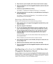
... Guide for more information. See Chapter 3, "Installing and Configuring SCSI Drivers," for removal. You can configure a 2 x 2 or 2 x 3 non-hot-pluggable SCSI backplane board as the drive is powered down. See Chapter 5, "Running the Dell Diagnostics," in Appendix B, "Jumpers and Switches," show the location of the connectors on the SCSI backplane boards.) Installing...
... Guide for more information. See Chapter 3, "Installing and Configuring SCSI Drivers," for removal. You can configure a 2 x 2 or 2 x 3 non-hot-pluggable SCSI backplane board as the drive is powered down. See Chapter 5, "Running the Dell Diagnostics," in Appendix B, "Jumpers and Switches," show the location of the connectors on the SCSI backplane boards.) Installing...
User's Guide
Page 108
...diskette, PCI1, PCI2, PCI3, PCI4, PCI5, PCI6, and built-in SCSI host adapter (supporting the internal drives). 7-8 Dell PowerEdge 2300 Systems User's Guide In descending order of precedence, the system boot order is automatically determined by the specific system configuration. The...attached to connector SCSIA on the SCSI backplane board supports SCSI slots 0 and 1 (see Figure 7-2). To configure a 2 x 2 or 2 x 3 non-hot-pluggable SCSI backplane board as a single backplane, connect the backplane board to connector SCSIB on the backplane board supports SCSI slots 3, 4, and 5. The SCSI ...
...diskette, PCI1, PCI2, PCI3, PCI4, PCI5, PCI6, and built-in SCSI host adapter (supporting the internal drives). 7-8 Dell PowerEdge 2300 Systems User's Guide In descending order of precedence, the system boot order is automatically determined by the specific system configuration. The...attached to connector SCSIA on the SCSI backplane board supports SCSI slots 0 and 1 (see Figure 7-2). To configure a 2 x 2 or 2 x 3 non-hot-pluggable SCSI backplane board as a single backplane, connect the backplane board to connector SCSIB on the backplane board supports SCSI slots 3, 4, and 5. The SCSI ...
User's Guide
Page 159
... video, mouse, and keyboard drivers are motherboard and logic board. Abbreviation for bootable diskette. Most TSR programs implement a predefined key combination (sometimes referred to as a "hot key") that should never be removed or disabled. However, some can sometimes cause memory conflicts. Abbreviation for example.
... video, mouse, and keyboard drivers are motherboard and logic board. Abbreviation for bootable diskette. Most TSR programs implement a predefined key combination (sometimes referred to as a "hot key") that should never be removed or disabled. However, some can sometimes cause memory conflicts. Abbreviation for example.
User's Guide
Page 165
...order, 7-8 cleaning, C-4 data recovery, C-1 drive bays, 7-2 drive carrier, illustrated, 7-6 failure indicator, 1-4 hard-disk drives (continued) hot-plug installation and removal, 7-4 indicator codes, 7-4 indicator lights, 7-5 installing, 7-4 partitioning and formatting, 7-4 replacing with system running, 7-4 SCSI... diskette drives formatting SCSI hard-disk drives, 7-4 front panel controls and indicators, 1-4 illustrated, 1-5 getting help tools, 1-6 hot-pluggable drives removing and installing, 7-4 I /O installing SCSI hard-disk drives, 7-1 interface connectors location on system board, 6-7,...
...order, 7-8 cleaning, C-4 data recovery, C-1 drive bays, 7-2 drive carrier, illustrated, 7-6 failure indicator, 1-4 hard-disk drives (continued) hot-plug installation and removal, 7-4 indicator codes, 7-4 indicator lights, 7-5 installing, 7-4 partitioning and formatting, 7-4 replacing with system running, 7-4 SCSI... diskette drives formatting SCSI hard-disk drives, 7-4 front panel controls and indicators, 1-4 illustrated, 1-5 getting help tools, 1-6 hot-pluggable drives removing and installing, 7-4 I /O installing SCSI hard-disk drives, 7-1 interface connectors location on system board, 6-7,...

User's Guide
Page 168
...for Windows NT, 3-2, 3-9 SCSI hard-disk drives bays, 7-2 configuring boot device, 7-8 SCSI hard-disk drives (continued) hot-plug removal and installation, 7-4 ID numbering, 7-3 indicator codes, 7-5 installing, 7-1 partitioning and formatting, 7-4 SCSI host ...backplane board about , B-1 autoconfiguration, 4-9 configuring, B-3 designations, B-1 disabling and enabling, 4-9 IRQ lines, B-3 pin assignments, B-4 6 Dell PowerEdge 2300 Systems User's Guide Resource Configuration Utility (continued) Steps in Configuring Your Computer menu, 5-5 system board options, 5-7 System Board Options screen,...
...for Windows NT, 3-2, 3-9 SCSI hard-disk drives bays, 7-2 configuring boot device, 7-8 SCSI hard-disk drives (continued) hot-plug removal and installation, 7-4 ID numbering, 7-3 indicator codes, 7-5 installing, 7-1 partitioning and formatting, 7-4 SCSI host ...backplane board about , B-1 autoconfiguration, 4-9 configuring, B-3 designations, B-1 disabling and enabling, 4-9 IRQ lines, B-3 pin assignments, B-4 6 Dell PowerEdge 2300 Systems User's Guide Resource Configuration Utility (continued) Steps in Configuring Your Computer menu, 5-5 system board options, 5-7 System Board Options screen,...
Installation and Troubleshooting Guide
Page 15
... Hard-Disk Drive 10-6 Removing a SCSI Hard-Disk Drive 10-7 Installing a Dell PowerEdge Expandable RAID Controller Host Adapter Card. . . . 10-8 Configuring a 2 x 2 or 2 x 3 SCSI Non-Hot-Pluggable Backplane Board 10-10 Configuring a Non-Hot-Pluggable Backplane Board as a Split Backplane Board 10-10 Configuring a Non-Hot-Pluggable Backplane Board as a Single Backplane Board 10-11 Installing...
... Hard-Disk Drive 10-6 Removing a SCSI Hard-Disk Drive 10-7 Installing a Dell PowerEdge Expandable RAID Controller Host Adapter Card. . . . 10-8 Configuring a 2 x 2 or 2 x 3 SCSI Non-Hot-Pluggable Backplane Board 10-10 Configuring a Non-Hot-Pluggable Backplane Board as a Split Backplane Board 10-10 Configuring a Non-Hot-Pluggable Backplane Board as a Single Backplane Board 10-11 Installing...

Installation and Troubleshooting Guide
Page 16
... A-7 1280 x 1024 16-Color Graphics Mode Screen A-7 Color Palettes Test A-7 Solid Colors Test A-7 Jumpers and Switches-A General Explanation B-1 Jumpers B-1 Switches B-2 System Board Labels B-5 Hot-Pluggable SCSI Backplane Board B-6 Non-Hot-Pluggable SCSI Backplane Boards B-7 Disabling a Forgotten Password B-8 Figure 2-1. Figure 3-1. Figure 7-1. Figure 5-1. Figure 2-2. Back Panel Features 2-3 Front Panel Features 2-4 Hard-Disk Drive Indicators...
... A-7 1280 x 1024 16-Color Graphics Mode Screen A-7 Color Palettes Test A-7 Solid Colors Test A-7 Jumpers and Switches-A General Explanation B-1 Jumpers B-1 Switches B-2 System Board Labels B-5 Hot-Pluggable SCSI Backplane Board B-6 Non-Hot-Pluggable SCSI Backplane Boards B-7 Disabling a Forgotten Password B-8 Figure 2-1. Figure 3-1. Figure 7-1. Figure 5-1. Figure 2-2. Back Panel Features 2-3 Front Panel Features 2-4 Hard-Disk Drive Indicators...

Installation and Troubleshooting Guide
Page 17
... Bezel 7-3 Figure 7-3. Expansion Cards 8-3 Figure 8-3. Power Connector 9-3 Figure 9-3. Removing the Computer Covers 7-4 Figure 7-4. Cable Configuration for a Dell PowerEdge Expandable RAID Controller Host Adapter Card 10-9 Figure 10-6. Attaching Drive Rails 9-7 Figure 10-1. Connectors on the 1 x 6 Hot-Pluggable SCSI Backplane Board. . . 10-13 Figure 11-1. Hard-DIsk Drive Indicators 10-5 Figure 10-4. Table 3-4. Removing...
... Bezel 7-3 Figure 7-3. Expansion Cards 8-3 Figure 8-3. Power Connector 9-3 Figure 9-3. Removing the Computer Covers 7-4 Figure 7-4. Cable Configuration for a Dell PowerEdge Expandable RAID Controller Host Adapter Card 10-9 Figure 10-6. Attaching Drive Rails 9-7 Figure 10-1. Connectors on the 1 x 6 Hot-Pluggable SCSI Backplane Board. . . 10-13 Figure 11-1. Hard-DIsk Drive Indicators 10-5 Figure 10-4. Table 3-4. Removing...

Installation and Troubleshooting Guide
Page 18
... Drive Indicator Patterns 10-5 Help Tools 11-2 International Dialing Codes 11-11 Dell Contact Numbers 11-12 Color Attributes A-4 System-Board Jumper Settings B-4 System Board Connectors and Sockets B-5 1 x 6 Hot-Pluggable SCSI Backplane Board Connectors B-6 2 x 2 Non-Hot-Pluggable SCSI Backplane Board Connectors B-7 2 x 3 Non-Hot-Pluggable SCSI Backplane Board Connectors B-8 xx Table 8-1. Table 11-1. Table 11...
... Drive Indicator Patterns 10-5 Help Tools 11-2 International Dialing Codes 11-11 Dell Contact Numbers 11-12 Color Attributes A-4 System-Board Jumper Settings B-4 System Board Connectors and Sockets B-5 1 x 6 Hot-Pluggable SCSI Backplane Board Connectors B-6 2 x 2 Non-Hot-Pluggable SCSI Backplane Board Connectors B-7 2 x 3 Non-Hot-Pluggable SCSI Backplane Board Connectors B-8 xx Table 8-1. Table 11-1. Table 11...

Installation and Troubleshooting Guide
Page 43
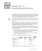
NOTE: If you do not have a Dell PowerEdge Expandable RAID Controller host adapter card installed, you will see Figure 3-1). hard-disk drive failure indicator hard-disk drive activity indicator hard-disk drive online ... installed, the "drive being prepared for removal" pattern appears, followed by the "drive ready for operation" pattern appears, followed by the SCSI backplane firmware. If a 1 x 6 hot-pluggable SCSI backplane board is installed in the system, three lightemitting diode (LED) indicators adjacent to each of the six SCSI hard-disk drive bays...
NOTE: If you do not have a Dell PowerEdge Expandable RAID Controller host adapter card installed, you will see Figure 3-1). hard-disk drive failure indicator hard-disk drive activity indicator hard-disk drive online ... installed, the "drive being prepared for removal" pattern appears, followed by the "drive ready for operation" pattern appears, followed by the SCSI backplane firmware. If a 1 x 6 hot-pluggable SCSI backplane board is installed in the system, three lightemitting diode (LED) indicators adjacent to each of the six SCSI hard-disk drive bays...
Installation and Troubleshooting Guide
Page 135
...drives in the external drive bays.) Three SCSI backplane board options are available, as the Dell PowerEdge Expandable RAID Controller. Figure 10-1 illustrates the hard-disk drive bays, the 1 x 6 hot-pluggable SCSI backplane board, and the Ultra2/low-voltage differential (LVD) SCSI cable. ...board Yes 1-inch drives No 1 x 6 backplane Yes* board No 1-inch drives Yes *Backplane board must be controlled by installing a hot-pluggable SCSI backplane board or a Dell PowerEdge Expandable RAID Controller host adapter card The hard-disk drive bays provide space for upgrading the system by...
...drives in the external drive bays.) Three SCSI backplane board options are available, as the Dell PowerEdge Expandable RAID Controller. Figure 10-1 illustrates the hard-disk drive bays, the 1 x 6 hot-pluggable SCSI backplane board, and the Ultra2/low-voltage differential (LVD) SCSI cable. ...board Yes 1-inch drives No 1 x 6 backplane Yes* board No 1-inch drives Yes *Backplane board must be controlled by installing a hot-pluggable SCSI backplane board or a Dell PowerEdge Expandable RAID Controller host adapter card The hard-disk drive bays provide space for upgrading the system by...
Installation and Troubleshooting Guide
Page 137
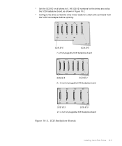
All SCSI ID numbers for a Start Unit command from the SCSI host adapter before spinning. SCSI ID 5 SCSI ID 0 1 x 6 hot-pluggable SCSI backplane board SCSI ID 5 SCSI ID 0 2 x 3 non-hot-pluggable SCSI backplane board SCSI ID 3 SCSI ID 0 2 x 2 non-hot-pluggable SCSI backplane board Installing Hard-Disk Drives 10-3 Configure the drive so that the drive motor waits for the drives are set by the SCSI backplane board, as shown in Figure 10-2. Set the SCSI ID on all drives to 0.
All SCSI ID numbers for a Start Unit command from the SCSI host adapter before spinning. SCSI ID 5 SCSI ID 0 1 x 6 hot-pluggable SCSI backplane board SCSI ID 5 SCSI ID 0 2 x 3 non-hot-pluggable SCSI backplane board SCSI ID 3 SCSI ID 0 2 x 2 non-hot-pluggable SCSI backplane board Installing Hard-Disk Drives 10-3 Configure the drive so that the drive motor waits for the drives are set by the SCSI backplane board, as shown in Figure 10-2. Set the SCSI ID on all drives to 0.


