Service Manual
Page 4
... 2-1 Initial User Contact 2-1 External Visual Inspection 2-2 Observing the Boot Routine 2-3 Internal Visual Inspection 2-4 Eliminating Resource Conflicts 2-5 Running the System Diagnostics 2-5 Getting Help 2-6 Chapter 3 Beep Codes and Error Messages 3-1 POST Beep Codes 3-1 System Error Messages 3-3 Chapter 4 Removing and Replacing Parts 4-1 Recommended Tools 4-1 Precautionary Measures 4-2 Computer Cover 4-3 Front Bezel 4-4 Front-Bezel Inserts 4-5 Control Panel Assembly 4-7 Drives...
... 2-1 Initial User Contact 2-1 External Visual Inspection 2-2 Observing the Boot Routine 2-3 Internal Visual Inspection 2-4 Eliminating Resource Conflicts 2-5 Running the System Diagnostics 2-5 Getting Help 2-6 Chapter 3 Beep Codes and Error Messages 3-1 POST Beep Codes 3-1 System Error Messages 3-3 Chapter 4 Removing and Replacing Parts 4-1 Recommended Tools 4-1 Precautionary Measures 4-2 Computer Cover 4-3 Front Bezel 4-4 Front-Bezel Inserts 4-5 Control Panel Assembly 4-7 Drives...

Service Manual
Page 6
... A-5. Exit Menu A-10 Tables Table 1-1. Table 1-5. Table 3-2. DC Voltage Ranges 1-10 Jumper Descriptions 1-16 Interrupt Assignments 1-17 DREQ Line Assignments 1-18 Technical Specifications 1-19 POST Beep Codes 3-1 System Error Messages 3-3 Key Functions A-2 Main Menu Categories A-4 Boot Options Submenu Categories A-5 Advanced Menu Categories A-7 Security Menu Categories A-9 Exit Menu Categories A-11 viii System Board...
... A-5. Exit Menu A-10 Tables Table 1-1. Table 1-5. Table 3-2. DC Voltage Ranges 1-10 Jumper Descriptions 1-16 Interrupt Assignments 1-17 DREQ Line Assignments 1-18 Technical Specifications 1-19 POST Beep Codes 3-1 System Error Messages 3-3 Key Functions A-2 Main Menu Categories A-4 Boot Options Submenu Categories A-5 Advanced Menu Categories A-7 Security Menu Categories A-9 Exit Menu Categories A-11 viii System Board...
Service Manual
Page 33
...on all peripherals and the computer. Does the fan run normally? This single beep is normal and is operational, troubleshoot the memory. 4. 9. If the system is set to step 4. Insert the Dell Server Assistant CD into the CD-ROM drive. Watch the Num Lock, Caps... next section, "Observing the Boot Routine." After all three indicators flash momentarily, and following : • Beep codes: A beep code is a series of beeps that the system power supply is not a beep code. During the boot routine, observe the system for any indications of problems. NOTE: Most of the steps ...
...on all peripherals and the computer. Does the fan run normally? This single beep is normal and is operational, troubleshoot the memory. 4. 9. If the system is set to step 4. Insert the Dell Server Assistant CD into the CD-ROM drive. Watch the Num Lock, Caps... next section, "Observing the Boot Routine." After all three indicators flash momentarily, and following : • Beep codes: A beep code is a series of beeps that the system power supply is not a beep code. During the boot routine, observe the system for any indications of problems. NOTE: Most of the steps ...

Service Manual
Page 37
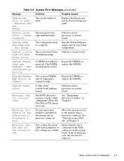
...Invalid expansion-card ROM checksum Improperly seated expansion card or the system needs rebooting. Beep Codes and Error Messages 3-1 Reseat the DIMMs or replace the system board. When the system emits a beep code, record the code and then find it in Chapter 2. See "Running the System Diagnostics" in .... If the table does not lead to the source of some failures, during normal system operation. Chapter 3 Beep Codes and Error Messages This chapter describes beep codes and system error messages that can occur during POST or, in the case of the problem, run the appropriate...
...Invalid expansion-card ROM checksum Improperly seated expansion card or the system needs rebooting. Beep Codes and Error Messages 3-1 Reseat the DIMMs or replace the system board. When the system emits a beep code, record the code and then find it in Chapter 2. See "Running the System Diagnostics" in .... If the table does not lead to the source of some failures, during normal system operation. Chapter 3 Beep Codes and Error Messages This chapter describes beep codes and system error messages that can occur during POST or, in the case of the problem, run the appropriate...

Service Manual
Page 38
... needs rebooting. Gate A20 failure Defective system board. 3-2 Dell PowerEdge 2200 Systems Service Manual Reseat the DIMMs or replace the system board. DRAM failure Defective DIMMs or system board. Keyboard controller error Defective DIMMs or system board. Gate A20 failure Defective system board. Beep Code 1-3-1-3 1-3-3-1 1-3-4-1 1-3-4-3 1-4-1-1 1-4-2-1 1-4-3-1 2-1-2-3 2-2-3-1 3-2-2-1 4-2-4-3 4-2-4-4 Table 3-1. POST Beep Codes (continued) Error Probable Causes Keyboard controller error Defective...
... needs rebooting. Gate A20 failure Defective system board. 3-2 Dell PowerEdge 2200 Systems Service Manual Reseat the DIMMs or replace the system board. DRAM failure Defective DIMMs or system board. Keyboard controller error Defective DIMMs or system board. Gate A20 failure Defective system board. Beep Code 1-3-1-3 1-3-3-1 1-3-4-1 1-3-4-3 1-4-1-1 1-4-2-1 1-4-3-1 2-1-2-3 2-2-3-1 3-2-2-1 4-2-4-3 4-2-4-4 Table 3-1. POST Beep Codes (continued) Error Probable Causes Keyboard controller error Defective...
Service Manual
Page 39
... reboot the system, and restore the EISA configuration. Expansion ROM not initialized Incorrect drive A type - The microprocessor speed jumper plug may have been accidentally installed. Beep Codes and Error Messages 3-3 Embedded There is removed; embedded server man- Download of these error messages indicate fatal errors. See "Eliminating Resource Conflicts" in NVRAM does...
... reboot the system, and restore the EISA configuration. Expansion ROM not initialized Incorrect drive A type - The microprocessor speed jumper plug may have been accidentally installed. Beep Codes and Error Messages 3-3 Embedded There is removed; embedded server man- Download of these error messages indicate fatal errors. See "Eliminating Resource Conflicts" in NVRAM does...
Service Manual
Page 41
... connector on the system board malfunctioned. write error Defective system board. See "Eliminating Resource Conflicts" in Chapter 4. Move the microprocessor to restore your system configuration. Beep Codes and Error Messages 3-5 System memory size has changed - Warning: System fan is not functioning The cooling-fan power cable is disconnected, or the cooling fan...
... connector on the system board malfunctioned. write error Defective system board. See "Eliminating Resource Conflicts" in Chapter 4. Move the microprocessor to restore your system configuration. Beep Codes and Error Messages 3-5 System memory size has changed - Warning: System fan is not functioning The cooling-fan power cable is disconnected, or the cooling fan...
Service Manual
Page 79
Index A AC power input connector, 1-5 AUXFAN connector, 4-15 B battery removal, 4-23 socket, 4-15 BATTERY socket, 4-15 beep codes about, 3-1 list of, 3-1 bezel removal, 4-4 boot routine observing when troubleshooting, 2-3 bracket hard-disk drive, removal, 4-11 C cables, DC power, 1-12 CD-ROM drive access indicator ...
Index A AC power input connector, 1-5 AUXFAN connector, 4-15 B battery removal, 4-23 socket, 4-15 BATTERY socket, 4-15 beep codes about, 3-1 list of, 3-1 bezel removal, 4-4 boot routine observing when troubleshooting, 2-3 bracket hard-disk drive, removal, 4-11 C cables, DC power, 1-12 CD-ROM drive access indicator ...
Service Manual
Page 81
..., 4-21 MOUSE connector, 4-15 P PANEL connector, 4-15 PARALLEL connector, 4-15 PCI expansion cards, 1-6 PCI expansion-card connectors, 4-15 Plug and Play ISA expansion cards, 1-6 POST beep codes, 3-1 power button, 1-3 POWER connector, 4-15 power indicator, 1-3 power supply about, 1-10 cables, 1-12 connectors, 1-10 DC voltage ranges, 1-10 illustrated, 1-12 power distribution diagram, 1-13...
..., 4-21 MOUSE connector, 4-15 P PANEL connector, 4-15 PARALLEL connector, 4-15 PCI expansion cards, 1-6 PCI expansion-card connectors, 4-15 Plug and Play ISA expansion cards, 1-6 POST beep codes, 3-1 power button, 1-3 POWER connector, 4-15 power indicator, 1-3 power supply about, 1-10 cables, 1-12 connectors, 1-10 DC voltage ranges, 1-10 illustrated, 1-12 power distribution diagram, 1-13...


