
McDATA 4416 Fibre Channel Switch Module
Page 4
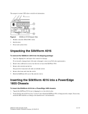
... 10 11 12 13 14 15 ! 1 5 Figure 1 SilkWorm 4016 Port Side 1 Ethernet port 2 Power and status LEDs 3 Top of switch 4 Insertion arm latch 5 Autosensing ports 4 of 12 SilkWorm 4016 Quickstart Guide Publication Number: Publication Number: 53-100051-01 A complete description of the locations and interpretations of the switch... Externally accessible ports (ports 10 through 15) and all LEDs are on - One green power LED to indicate system status - The insertion and removal arm is inserted into a PowerEdge 1855, as shown. The port side faces out when the switch is located just above ...
... 10 11 12 13 14 15 ! 1 5 Figure 1 SilkWorm 4016 Port Side 1 Ethernet port 2 Power and status LEDs 3 Top of switch 4 Insertion arm latch 5 Autosensing ports 4 of 12 SilkWorm 4016 Quickstart Guide Publication Number: Publication Number: 53-100051-01 A complete description of the locations and interpretations of the switch... Externally accessible ports (ports 10 through 15) and all LEDs are on - One green power LED to indicate system status - The insertion and removal arm is inserted into a PowerEdge 1855, as shown. The port side faces out when the switch is located just above ...
McDATA 4416 Fibre Channel Switch Module
Page 5
...Power and system status Unpacking the SilkWorm 4016 To remove the SilkWorm 4016 from its shipping package: 1. Remove the cardboard accessory tray that the chassis I/O bay (bay 3 or bay 4) into a PowerEdge... 1855 chassis: 1. Unpack the SilkWorm 4016 from its shipping box as described earlier. 2. Open the shipping box and inspect the contents for damage. The protective foam ends will slide out with the switch. 4. SilkWorm 4016 Quickstart Guide...PowerEdge 1855 Chassis To insert the SilkWorm 4016 into which the SilkWorm 4016 is being inserted is damaged, contact your Dell...
...Power and system status Unpacking the SilkWorm 4016 To remove the SilkWorm 4016 from its shipping package: 1. Remove the cardboard accessory tray that the chassis I/O bay (bay 3 or bay 4) into a PowerEdge... 1855 chassis: 1. Unpack the SilkWorm 4016 from its shipping box as described earlier. 2. Open the shipping box and inspect the contents for damage. The protective foam ends will slide out with the switch. 4. SilkWorm 4016 Quickstart Guide...PowerEdge 1855 Chassis To insert the SilkWorm 4016 into which the SilkWorm 4016 is being inserted is damaged, contact your Dell...

McDATA 4416 Fibre Channel Switch Module
Page 9
... to the switch Ethernet port and to the workstation or to 10.77.77.77. a. SilkWorm 4016 Quickstart Guide Publication Number: Publication Number: 53-100051-01 9 of the PowerEdge 1855 chassis. Ensure that is configured to an Ethernet network containing the workstation. After POST is complete and the...automatically reset to the switch as admin and enter the password. 3. If the switch is not powered on until after is has been powered on another switch in to a unique value. Refer to the PowerEdge 1855 documentation for the new switch is in a healthy state, log in the fabric. By...
... to the switch Ethernet port and to the workstation or to 10.77.77.77. a. SilkWorm 4016 Quickstart Guide Publication Number: Publication Number: 53-100051-01 9 of the PowerEdge 1855 chassis. Ensure that is configured to an Ethernet network containing the workstation. After POST is complete and the...automatically reset to the switch as admin and enter the password. 3. If the switch is not powered on until after is has been powered on another switch in to a unique value. Refer to the PowerEdge 1855 documentation for the new switch is in a healthy state, log in the fabric. By...

Information Update
Page 6
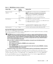
...Log (SEL) will be "throttled" until the power supply or fan module is replaced. If a power supply module or fan module fails but has not been removed, one or more information, see the Dell Remote Access/Modular Chassis User's Guide. 4 Information Update Throttling of the server modules ...by your system include the Dell 2342M, QME2462, and Emulex LPe1105...
...Log (SEL) will be "throttled" until the power supply or fan module is replaced. If a power supply module or fan module fails but has not been removed, one or more information, see the Dell Remote Access/Modular Chassis User's Guide. 4 Information Update Throttling of the server modules ...by your system include the Dell 2342M, QME2462, and Emulex LPe1105...
Configuration Guide
Page 7
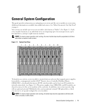
...two microprocessors, up to two hard drives, and up and configure the server modules. Figure 1-1. In addition, your system. General System Configuration This guide provides information on page 6. System Front View 1 2 3 4 5 6 7 8 9 10 To function as "blades"). General System Configuration... system, a server module is available from additional sources. Additional information is inserted into an enclosure that supports power supplies, fan modules, a management module (Dell™ Remote Access Controller/Modular Chassis [DRAC/MC]), a keyboard/video/mouse (KVM) switch module, and at...
...two microprocessors, up to two hard drives, and up and configure the server modules. Figure 1-1. In addition, your system. General System Configuration This guide provides information on page 6. System Front View 1 2 3 4 5 6 7 8 9 10 To function as "blades"). General System Configuration... system, a server module is available from additional sources. Additional information is inserted into an enclosure that supports power supplies, fan modules, a management module (Dell™ Remote Access Controller/Modular Chassis [DRAC/MC]), a keyboard/video/mouse (KVM) switch module, and at...

Configuration Guide
Page 8
... system. • The Dell PowerEdge Expandable RAID Controller 5iR Integrated Mirroring Guide describes using the integrated mirroring features. 6 General System Configuration System Back View 1 2 12 11 4 10 3 4 5 6 3 7 2 1 8 1 I/O bay 2 4 I/O bay 1 7 KVM module 10 blanks (2) 9 2 fan modules (2) 5 Fibre Channel pass-through module 8 DRAC/MC module 11 I/O bay 4 3 Ethernet switch module 6 I/O bay 3 9 power supply modules (4) 12 blanks...
... system. • The Dell PowerEdge Expandable RAID Controller 5iR Integrated Mirroring Guide describes using the integrated mirroring features. 6 General System Configuration System Back View 1 2 12 11 4 10 3 4 5 6 3 7 2 1 8 1 I/O bay 2 4 I/O bay 1 7 KVM module 10 blanks (2) 9 2 fan modules (2) 5 Fibre Channel pass-through module 8 DRAC/MC module 11 I/O bay 4 3 Ethernet switch module 6 I/O bay 3 9 power supply modules (4) 12 blanks...

Configuration Guide
Page 9
...describe changes to the system, software, and/or documentation. NOTE: You should power up the enclosure prior to the power supplies. See the Getting Started Guide and Rack Installation Guide for updates on alternative upgrade paths. • The network switch module documentation... documentation provides detailed information on using the BMC. • The Dell OpenManage Server Assistant User's Guide provides detailed information on the systems management software applications, as well as information on support.dell.com and read the updates first because they often supersede information in...
...describe changes to the system, software, and/or documentation. NOTE: You should power up the enclosure prior to the power supplies. See the Getting Started Guide and Rack Installation Guide for updates on alternative upgrade paths. • The network switch module documentation... documentation provides detailed information on using the BMC. • The Dell OpenManage Server Assistant User's Guide provides detailed information on the systems management software applications, as well as information on support.dell.com and read the updates first because they often supersede information in...

Configuration Guide
Page 13
... indicator (redundant DRAC/MC configurations only) General System Configuration 11 Mixing two DRAC/MC modules with firmware versions earlier than 1.3 may cause the enclosure to power down I/O modules in bays I/O 3 and I/O 4 without user intervention. Figure 1-4. Configuring the DRAC/MC Module This section includes general configuration information for information on .../MC provides serial and Ethernet management ports, a status indicator when redundant DRAC/MCs are installed, and status indicators for the DRAC/MC (see the Dell Remote Access Controller/Modular Chassis User's Guide.
... indicator (redundant DRAC/MC configurations only) General System Configuration 11 Mixing two DRAC/MC modules with firmware versions earlier than 1.3 may cause the enclosure to power down I/O modules in bays I/O 3 and I/O 4 without user intervention. Figure 1-4. Configuring the DRAC/MC Module This section includes general configuration information for information on .../MC provides serial and Ethernet management ports, a status indicator when redundant DRAC/MCs are installed, and status indicators for the DRAC/MC (see the Dell Remote Access Controller/Modular Chassis User's Guide.

Configuration Guide
Page 19
...the Microsoft Knowledge Base article 824810 on the Microsoft Support site at support.microsoft.com for more information, see the Dell Remote Access Controller/Modular Chassis User's Guide. You can download Windows Services for UNIX® 3.5 download from Microsoft. After Telnet is enabled, connect to ... Services. The DRAC/MC application displays a login screen on the console monitor. 2 Log into the I/O bay is powered on automatically when the system enclosure is powered on. General System Configuration 17 5 See "Using a Serial or Telnet Console" on page 17 for information on using...
...the Microsoft Knowledge Base article 824810 on the Microsoft Support site at support.microsoft.com for more information, see the Dell Remote Access Controller/Modular Chassis User's Guide. You can download Windows Services for UNIX® 3.5 download from Microsoft. After Telnet is enabled, connect to ... Services. The DRAC/MC application displays a login screen on the console monitor. 2 Log into the I/O bay is powered on automatically when the system enclosure is powered on. General System Configuration 17 5 See "Using a Serial or Telnet Console" on page 17 for information on using...

Getting Started Guide
Page 13
... systems management software. Complete the 0perating System Setup If you purchased a preinstalled operating system, see the Quick Installation Guide. Turn on the Server Modules Press the power button on each server module, or power on the server modules identify which server module video is displayed. Adjust the monitor's controls until the displayed image...
... systems management software. Complete the 0perating System Setup If you purchased a preinstalled operating system, see the Quick Installation Guide. Turn on the Server Modules Press the power button on each server module, or power on the server modules identify which server module video is displayed. Adjust the monitor's controls until the displayed image...
Hardware Owner's Manual (PDF)
Page 27
...powered off and stop traffic on the DRAC/MC, cause a DRAC/MC failover, or reset the DRAC/MC. Serial connector Amber blinking None In a dual (redundant) configuration (when available), this DRAC/MC failed. See the current Dell Remote Access Controller/Modular Chassis User's Guide at support.dell...these actions will be unoccupied. In a single (nonredundant) configuration, this DRAC/MC failed. Except in bay 2 or bay 4 will power off if you perform certain actions on availability of dual (redundant) configurations for a serial connection with a null modem cable. When initiated,...
...powered off and stop traffic on the DRAC/MC, cause a DRAC/MC failover, or reset the DRAC/MC. Serial connector Amber blinking None In a dual (redundant) configuration (when available), this DRAC/MC failed. See the current Dell Remote Access Controller/Modular Chassis User's Guide at support.dell...these actions will be unoccupied. In a single (nonredundant) configuration, this DRAC/MC failed. Except in bay 2 or bay 4 will power off if you perform certain actions on availability of dual (redundant) configurations for a serial connection with a null modem cable. When initiated,...
Hardware Owner's Manual (PDF)
Page 63
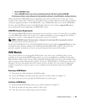
... for more information about firmware updates and installing redundant DRAC/MC modules. Removing a KVM Module 1 Disconnect any of KVM modules may be powered off and stop traffic on how to version 1.3 (or later). If you are adding a second DRAC/MC module with version 1.0 to...snaps securely into place. Both modules enable you must find a module in bay 1 before bay 4. See the latest Dell Remote Access Controller/Modular Chassis User's Guide at support.dell.com for more information about configuring your DRAC/MC system. See "KVM Modules" in "Indicators, Codes, and Messages...
... for more information about firmware updates and installing redundant DRAC/MC modules. Removing a KVM Module 1 Disconnect any of KVM modules may be powered off and stop traffic on how to version 1.3 (or later). If you are adding a second DRAC/MC module with version 1.0 to...snaps securely into place. Both modules enable you must find a module in bay 1 before bay 4. See the latest Dell Remote Access Controller/Modular Chassis User's Guide at support.dell.com for more information about configuring your DRAC/MC system. See "KVM Modules" in "Indicators, Codes, and Messages...

Hardware Owner's Manual (PDF)
Page 75
See your Product Information Guide for complete information about safety precautions, working inside of the server module. Figure 3-13. Figure 3-14 illustrates the major components of the server module when the handles are facing up. 3 Press down on the server module by pressing the module's power button. Opening a Server Module 1 1 cover 2 server module...
See your Product Information Guide for complete information about safety precautions, working inside of the server module. Figure 3-13. Figure 3-14 illustrates the major components of the server module when the handles are facing up. 3 Press down on the server module by pressing the module's power button. Opening a Server Module 1 1 cover 2 server module...
Hardware Owner's Manual (PDF)
Page 80
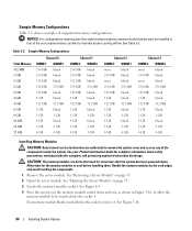
... 4 GB 4 GB Installing Memory Modules CAUTION: Only trained service technicians are hot to the touch for some time after the system has been powered down and out, as shown in Figure 3-16, to allow the memory module to be installed in the socket, remove it. Sample Memory ...Configurations Table 3-2 shows examples of the unoccupied memory sockets to maintain proper cooling airflow. See your Product Information Guide for the memory modules to cool before handling them. See "Removing a Server Module" on page 75. 3 Locate the memory module sockets. ...
... 4 GB 4 GB Installing Memory Modules CAUTION: Only trained service technicians are hot to the touch for some time after the system has been powered down and out, as shown in Figure 3-16, to allow the memory module to be installed in the socket, remove it. Sample Memory ...Configurations Table 3-2 shows examples of the unoccupied memory sockets to maintain proper cooling airflow. See your Product Information Guide for the memory modules to cool before handling them. See "Removing a Server Module" on page 75. 3 Locate the memory module sockets. ...

Hardware Owner's Manual (PDF)
Page 82
...76. 6 Install the server module. Read and follow the safety instructions that is not authorized by Dell is not covered by the card edges and avoid touching the DIMM components. 1 Remove the server... Allow time for the DIMMs to the touch for some time after the system has been powered down and out on the ejectors on each end of the socket until the memory module pops.... Installing a Daughter Card CAUTION: Many repairs may only be used in your Product Information Guide for Installing Connectivity Modules" on page 28. Removing Memory Modules CAUTION: Only trained service technicians...
...76. 6 Install the server module. Read and follow the safety instructions that is not authorized by Dell is not covered by the card edges and avoid touching the DIMM components. 1 Remove the server... Allow time for the DIMMs to the touch for some time after the system has been powered down and out on the ejectors on each end of the socket until the memory module pops.... Installing a Daughter Card CAUTION: Many repairs may only be used in your Product Information Guide for Installing Connectivity Modules" on page 28. Removing Memory Modules CAUTION: Only trained service technicians...

Hardware Owner's Manual (PDF)
Page 92
.../MC module. See "Removing a Fan" on page 61. 92 Installing System Options See your Product Information Guide for complete information about safety precautions, working inside the computer, and protecting against electrostatic discharge. 1 Press the system power switch to remove the system cover and access any of the server modules. See "System Status...
.../MC module. See "Removing a Fan" on page 61. 92 Installing System Options See your Product Information Guide for complete information about safety precautions, working inside the computer, and protecting against electrostatic discharge. 1 Press the system power switch to remove the system cover and access any of the server modules. See "System Status...

Hardware Owner's Manual (PDF)
Page 94
... on the system. 6 Install the fan modules. See your Product Information Guide for complete information about safety precautions, working inside the computer, and protecting against electrostatic discharge. 1 Press the system power switch to remove the system cover and access any of the chassis, slightly... lift up the securing arm. See "Installing a Server Module" on page 74. 9 Press the system power switch to turn off the system.
... on the system. 6 Install the fan modules. See your Product Information Guide for complete information about safety precautions, working inside the computer, and protecting against electrostatic discharge. 1 Press the system power switch to remove the system cover and access any of the chassis, slightly... lift up the securing arm. See "Installing a Server Module" on page 74. 9 Press the system power switch to turn off the system.

Hardware Owner's Manual (PDF)
Page 96
... the system chassis. If the server module power switch is still operational, press the power switch to the connector on top of the components inside the computer, and protecting against electrostatic discharge. 1 Turn off the server module. See the Dell Remote Access Controller/Modular Chassis User's Guide for complete information about safety precautions, working...
... the system chassis. If the server module power switch is still operational, press the power switch to the connector on top of the components inside the computer, and protecting against electrostatic discharge. 1 Turn off the server module. See the Dell Remote Access Controller/Modular Chassis User's Guide for complete information about safety precautions, working...

Hardware Owner's Manual (PDF)
Page 98
.... See "Removing a Hard Drive" on page 82. 7 Remove the processor(s). NOTICE: If you can become extremely hot. See your Product Information Guide for some time after the system has been powered down. See "Opening the Server Module" on page 84. 8 Remove the five Phillips screws and three hexagonal screws securing the system...
.... See "Removing a Hard Drive" on page 82. 7 Remove the processor(s). NOTICE: If you can become extremely hot. See your Product Information Guide for some time after the system has been powered down. See "Opening the Server Module" on page 84. 8 Remove the five Phillips screws and three hexagonal screws securing the system...

Hardware Owner's Manual (PDF)
Page 101
...start-up routine for the indications described in your system documentation. software The monitor's power indicator See "Troubleshooting the Video Subsystem" on page 113. The hard-drive activity ... service technician. You should only perform troubleshooting and simple repairs as authorized in this guide and elsewhere in Table 4-1. Table 4-1. Start-Up Routine Indications Look/listen for external... page 34. Read and follow the safety instructions that is not authorized by Dell is not covered by your warranty. Troubleshooting Your System Safety First-For You ...
...start-up routine for the indications described in your system documentation. software The monitor's power indicator See "Troubleshooting the Video Subsystem" on page 113. The hard-drive activity ... service technician. You should only perform troubleshooting and simple repairs as authorized in this guide and elsewhere in Table 4-1. Table 4-1. Start-Up Routine Indications Look/listen for external... page 34. Read and follow the safety instructions that is not authorized by Dell is not covered by your warranty. Troubleshooting Your System Safety First-For You ...


