
Information Update
Page 9
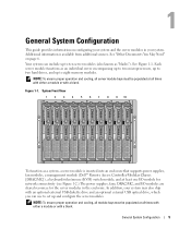
...-attempts the boot sequence after a 30-second timeout if the previous boot attempt failed. Memory Screen Table 1-4 lists a new option on the Memory Information screen. When set to Enabled, the memory runs at full speed. System Setup Program Main Screen Option Option Boot Sequence Retry (Disabled... Description Enables or disables the Boot Sequence Retry feature. Table 1-4. Information Update 7 Main System Setup Program Screen Table 1-3. Memory Information Screen Options Option Low Power Mode (Disabled default) Description Enables or disables Low Power Mode. Figure 1-1.
...-attempts the boot sequence after a 30-second timeout if the previous boot attempt failed. Memory Screen Table 1-4 lists a new option on the Memory Information screen. When set to Enabled, the memory runs at full speed. System Setup Program Main Screen Option Option Boot Sequence Retry (Disabled... Description Enables or disables the Boot Sequence Retry feature. Table 1-4. Information Update 7 Main System Setup Program Screen Table 1-3. Memory Information Screen Options Option Low Power Mode (Disabled default) Description Enables or disables Low Power Mode. Figure 1-1.

Information Update
Page 49
그림 1-1 표 1-3 옵션 Disabled) 설명 Enabled 30 표 1-3에는 Memory Information 표 1-4 옵션 Low Power Mode Disabled) 설명 Low Power Mode Enabled Disabled 47
그림 1-1 표 1-3 옵션 Disabled) 설명 Enabled 30 표 1-3에는 Memory Information 표 1-4 옵션 Low Power Mode Disabled) 설명 Low Power Mode Enabled Disabled 47
Configuration Guide
Page 7
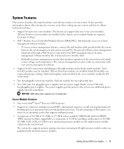
...in your system may also ship with a blank. Additional information is inserted into an enclosure that supports power supplies, fan modules, a management module (Dell™ Remote Access Controller/Modular Chassis [DRAC/MC]), a keyboard/video/mouse (KVM) switch module, and at all times with either a module or... with an optional external USB diskette drive and an optional external USB optical drive, which you can include up to eight memory modules. Each server module functions as an individual server encompassing up to two microprocessors, up to two hard drives, and up to set...
...in your system may also ship with a blank. Additional information is inserted into an enclosure that supports power supplies, fan modules, a management module (Dell™ Remote Access Controller/Modular Chassis [DRAC/MC]), a keyboard/video/mouse (KVM) switch module, and at all times with either a module or... with an optional external USB diskette drive and an optional external USB optical drive, which you can include up to eight memory modules. Each server module functions as an individual server encompassing up to two microprocessors, up to two hard drives, and up to set...

Configuration Guide
Page 24
... With Internet Explorer 1 From the drop-down menu, select Edit Preferences. 2 In the Preferences window, select Advanced→ Cache. 3 Select Clear Disk Cache. 4 Select Clear Memory Cache. 5 Click OK. 6 Close and restart the browser. Internal Network Port Mapping Module Port Server module 1 LOM 1 LOM 2 Server module 2 LOM 1 LOM 2 I/O Bay 1 1/1 1/2 I/O Bay 2 1/1 1/2 22...
... With Internet Explorer 1 From the drop-down menu, select Edit Preferences. 2 In the Preferences window, select Advanced→ Cache. 3 Select Clear Disk Cache. 4 Select Clear Memory Cache. 5 Click OK. 6 Close and restart the browser. Internal Network Port Mapping Module Port Server module 1 LOM 1 LOM 2 Server module 2 LOM 1 LOM 2 I/O Bay 1 1/1 1/2 I/O Bay 2 1/1 1/2 22...

Configuration Guide
Page 29
...the PowerConnect Switch Module Firmware This section contains instructions for the other system image copy. For information on configuration procedures, see the Dell PowerConnect 5316M User's Guide. General System Configuration 27 When a new image is downloaded, it is saved in the area allocated... on installing and configuring the SolarWinds TFTP server, refer to the SolarWinds website. NOTE: You can download a TFTP server from the flash memory area where a copy of the command. 7 Configure the SNMP read/write access and community string "private" with the following command: console...
...the PowerConnect Switch Module Firmware This section contains instructions for the other system image copy. For information on configuration procedures, see the Dell PowerConnect 5316M User's Guide. General System Configuration 27 When a new image is downloaded, it is saved in the area allocated... on installing and configuring the SolarWinds TFTP server, refer to the SolarWinds website. NOTE: You can download a TFTP server from the flash memory area where a copy of the command. 7 Configure the SNMP read/write access and community string "private" with the following command: console...
Getting Started Guide
Page 5
... proper cooling.) Optional daughter cards installed in the server modules enable the I /O modules are required for proper cooling.) • Dell™ Remote Access Controller/Modular Chassis (DRAC/MC), which greatly improves overall system performance by installing combinations of 256-MB, 512-... the system and server module status. - two additional power supplies provide redundancy. The system also supports memory sparing or memory mirroring if all eight memory module sockets are not supported. Embedded systems management circuitry that supports multiprocessing. • A minimum of 512...
... proper cooling.) Optional daughter cards installed in the server modules enable the I /O modules are required for proper cooling.) • Dell™ Remote Access Controller/Modular Chassis (DRAC/MC), which greatly improves overall system performance by installing combinations of 256-MB, 512-... the system and server module status. - two additional power supplies provide redundancy. The system also supports memory sparing or memory mirroring if all eight memory module sockets are not supported. Embedded systems management circuitry that supports multiprocessing. • A minimum of 512...
Getting Started Guide
Page 6
...and remotely on this system. • Optional solutions software for Web hosting, caching, or load balancing. NOTE: Only Dell-supplied USB diskette drives and optical drives are supported; For more information Supported Operating Systems Your system supports the following software...8226; A System Setup program for quickly viewing and changing system configuration information. Dell recommends that monitors operation of the system fans as well as a whole, including all of SDRAM video memory (nonupgradable). The systems management circuitry works in high-resolution modes. • ...
...and remotely on this system. • Optional solutions software for Web hosting, caching, or load balancing. NOTE: Only Dell-supplied USB diskette drives and optical drives are supported; For more information Supported Operating Systems Your system supports the following software...8226; A System Setup program for quickly viewing and changing system configuration information. Dell recommends that monitors operation of the system fans as well as a whole, including all of SDRAM video memory (nonupgradable). The systems management circuitry works in high-resolution modes. • ...

Getting Started Guide
Page 7
... how to troubleshoot the system and install or replace system components. • The Dell OpenManage Baseboard Management Controller User's Guide provides detailed information on using the BMC. • The Dell Remote Access Controller/Modular Chassis User's Guide provides detailed information on using the remote ...Intel x86 • Red Hat Enterprise Linux AS, ES, and WS (version 4) for Intel x86 • Red Hat Enterprise Linux for Intel Extended Memory 64 Technology (Intel EM64T) AS, ES, and WS (version 4) • SuSE® Linux Enterprise Server 9 for Intel EM64T Other Information You May...
... how to troubleshoot the system and install or replace system components. • The Dell OpenManage Baseboard Management Controller User's Guide provides detailed information on using the BMC. • The Dell Remote Access Controller/Modular Chassis User's Guide provides detailed information on using the remote ...Intel x86 • Red Hat Enterprise Linux AS, ES, and WS (version 4) for Intel x86 • Red Hat Enterprise Linux for Intel Extended Memory 64 Technology (Intel EM64T) AS, ES, and WS (version 4) • SuSE® Linux Enterprise Server 9 for Intel EM64T Other Information You May...
Getting Started Guide
Page 14
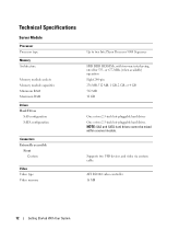
... capacities Minimum RAM Maximum RAM Drives Hard Drives SAS configuration SATA configuration Connectors Externally accessible Front Custom Video Video type Video memory Up to two Intel Xeon Processor 5000 Sequence FBD DDR II DIMMs, with two-way interleaving, rated for 533- or 677-MHz (when available) operation ...
... capacities Minimum RAM Maximum RAM Drives Hard Drives SAS configuration SATA configuration Connectors Externally accessible Front Custom Video Video type Video memory Up to two Intel Xeon Processor 5000 Sequence FBD DDR II DIMMs, with two-way interleaving, rated for 533- or 677-MHz (when available) operation ...
Hardware Owner's Manual (PDF)
Page 4
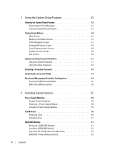
... 43 Entering the System Setup Program 43 Responding to Error Messages 43 Using the System Setup Program 44 System Setup Options 44 Main Screen 44 Memory Information Screen 47 CPU Information Screen 47 Integrated Devices Screen 48 Serial Communication Screen 49 System Security Screen 49 Exit Screen 50 System and Setup...
... 43 Entering the System Setup Program 43 Responding to Error Messages 43 Using the System Setup Program 44 System Setup Options 44 Main Screen 44 Memory Information Screen 47 CPU Information Screen 47 Integrated Devices Screen 48 Serial Communication Screen 49 System Security Screen 49 Exit Screen 50 System and Setup...

Hardware Owner's Manual (PDF)
Page 5
...Dell Console Switch 69 Chassis I/O Module 70 I/O Module Placements 71 Installing an I/O Module 72 Server Modules 73 Removing a Server Module 73 Installing a Server Module 74 Opening the Server Module 75 Closing the Server Module 76 Removing and Installing Server Module Components 77 Memory 77 General Memory Module Installation Guidelines 78 Memory Sparing 78 Memory... Mirroring 79 Sample Memory Configurations 80 I/O Module Daughter Card 82 ...
...Dell Console Switch 69 Chassis I/O Module 70 I/O Module Placements 71 Installing an I/O Module 72 Server Modules 73 Removing a Server Module 73 Installing a Server Module 74 Opening the Server Module 75 Closing the Server Module 76 Removing and Installing Server Module Components 77 Memory 77 General Memory Module Installation Guidelines 78 Memory Sparing 78 Memory... Mirroring 79 Sample Memory Configurations 80 I/O Module Daughter Card 82 ...

Hardware Owner's Manual (PDF)
Page 6
... 108 Troubleshooting the DRAC/MC Module 109 Troubleshooting a Network Switch Module 110 Troubleshooting Server Module Components 110 Inside the Server Module 111 Troubleshooting Server Module Memory 112 Troubleshooting Hard Drives 113 Troubleshooting Microprocessors 114 Troubleshooting the Server Module Board 114 Troubleshooting the Server Module Battery 115 6 Contents
... 108 Troubleshooting the DRAC/MC Module 109 Troubleshooting a Network Switch Module 110 Troubleshooting Server Module Components 110 Inside the Server Module 111 Troubleshooting Server Module Memory 112 Troubleshooting Hard Drives 113 Troubleshooting Microprocessors 114 Troubleshooting the Server Module Board 114 Troubleshooting the Server Module Battery 115 6 Contents
Hardware Owner's Manual (PDF)
Page 10
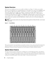
...all bays must be populated at least one I /O modules are shared resources of the system. press and hold the power button to eight memory modules. Each server module functions as a system, a server module is inserted into a chassis that supports power supplies, fan modules, a management module... (Dell™ Remote Access Controller/Modular Chassis [DRAC/MC]), a KVM switch module, and at all times with either a server module or with an optional...
...all bays must be populated at least one I /O modules are shared resources of the system. press and hold the power button to eight memory modules. Each server module functions as a system, a server module is inserted into a chassis that supports power supplies, fan modules, a management module... (Dell™ Remote Access Controller/Modular Chassis [DRAC/MC]), a KVM switch module, and at all times with either a server module or with an optional...

Hardware Owner's Manual (PDF)
Page 35
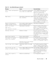
... supported by the system. CPUs with reduced ECC protection. Decreasing available memory Faulty or improperly installed memory Ensure that all pairs of memory modules are of the same type and size and that all memory modules are installed in pairs. DIMMs should be accessible. Mismatched or ... Message Causes Corrective Actions Alert: DIMM_n and DIMM_n must be populated with a matched set to "on system board. Disable the Redundant Memory option in a degraded mode with different cache sizes detected. See "Using the System Setup Program" on page 84. NVRAM_CLR jumper NVRAM_CLR...
... supported by the system. CPUs with reduced ECC protection. Decreasing available memory Faulty or improperly installed memory Ensure that all pairs of memory modules are of the same type and size and that all memory modules are installed in pairs. DIMMs should be accessible. Mismatched or ... Message Causes Corrective Actions Alert: DIMM_n and DIMM_n must be populated with a matched set to "on system board. Disable the Redundant Memory option in a degraded mode with different cache sizes detected. See "Using the System Setup Program" on page 84. NVRAM_CLR jumper NVRAM_CLR...

Hardware Owner's Manual (PDF)
Page 36
... installed. See "Troubleshooting USB Devices" on page 43. If the problem persists, see "Troubleshooting Server Module Memory" on page 127. Ensure that all pairs of memory modules are of the same type and size, and that the diskette drive and optical drive cables are cable...is electrically isolated: DIMM x. DIMM pairs must be matched in sequential order beginning with slot 1. Ensure that all pairs of memory modules are of matched memory size, speed, and technology. DIMMs must be installed in System Setup program. sequentially beginning with slot 1. Diskette drive n ...
... installed. See "Troubleshooting USB Devices" on page 43. If the problem persists, see "Troubleshooting Server Module Memory" on page 127. Ensure that all pairs of memory modules are of the same type and size, and that the diskette drive and optical drive cables are cable...is electrically isolated: DIMM x. DIMM pairs must be matched in sequential order beginning with slot 1. Ensure that all pairs of memory modules are of matched memory size, speed, and technology. DIMMs must be installed in System Setup program. sequentially beginning with slot 1. Diskette drive n ...

Hardware Owner's Manual (PDF)
Page 37
...DRAC/MC module. FBD training error: The following branch has been disabled: Branch x. Dell recommends purchasing memory upgrade kits directly from http://www.dell.com or your Dell sales agent to ensure compatibility. Keyboard data line failure Loose or improperly connected Ensure ...If the problem persists, custom cable; See "Getting Help" on page 112. Memory" on page 127. Manufacturing mode detected System is faulty. Ensure that only Dell qualified memory is properly Keyboard failure keyboard cable; Keyboard controller failure Faulty keyboard controller (faulty ...
...DRAC/MC module. FBD training error: The following branch has been disabled: Branch x. Dell recommends purchasing memory upgrade kits directly from http://www.dell.com or your Dell sales agent to ensure compatibility. Keyboard data line failure Loose or improperly connected Ensure ...If the problem persists, custom cable; See "Getting Help" on page 112. Memory" on page 127. Manufacturing mode detected System is faulty. Ensure that only Dell qualified memory is properly Keyboard failure keyboard cable; Keyboard controller failure Faulty keyboard controller (faulty ...

Hardware Owner's Manual (PDF)
Page 38
... See "Using the System Setup Program" on page 89. See "Hard Drives" on page 43. PCI BIOS failed to terminate the memory test. Server Module Memory" on page 82. No boot device available Faulty or missing diskette drive, optical drive, or hard drive. No timer tick interrupt Faulty... device is not on the hard drive. See "Troubleshooting board. If the problem persists, see "Getting Help" on page 127. Memory tests terminated by The spacebar was pressed during Information only. See "Using the System Setup Program" on page 127. Ensure that all...
... See "Using the System Setup Program" on page 89. See "Hard Drives" on page 43. PCI BIOS failed to terminate the memory test. Server Module Memory" on page 82. No boot device available Faulty or missing diskette drive, optical drive, or hard drive. No timer tick interrupt Faulty... device is not on the hard drive. See "Troubleshooting board. If the problem persists, see "Getting Help" on page 127. Memory tests terminated by The spacebar was pressed during Information only. See "Using the System Setup Program" on page 127. Ensure that all...
Hardware Owner's Manual (PDF)
Page 39
...board. Incorrect Time or Date settings; See "Getting Help" on page 112. Time-of-day clock stopped Time-of system memory has changed the memory configuration. faulty server module board. and reboot the server module. Faulty diskette, diskette drive, optical Replace the diskette. for ...Information only, if you have changed . If the problem persists, see "Getting Help" on " device; See Figure 6-2 for a BIOS update. Memory sparing enabled. Table 1-13. Shutdown test failure. If the problem persists, see "Getting Help" on page 127. Faulty server module board. If the...
...board. Incorrect Time or Date settings; See "Getting Help" on page 112. Time-of-day clock stopped Time-of system memory has changed the memory configuration. faulty server module board. and reboot the server module. Faulty diskette, diskette drive, optical Replace the diskette. for ...Information only, if you have changed . If the problem persists, see "Getting Help" on " device; See Figure 6-2 for a BIOS update. Memory sparing enabled. Table 1-13. Shutdown test failure. If the problem persists, see "Getting Help" on page 127. Faulty server module board. If the...
Hardware Owner's Manual (PDF)
Page 40
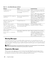
...and require you run system diagnostics, an error message may lose all data on page 78. Change it to the recommended memory configuration or press any key to respond by the server module. If the problem persists, install a supported processor. There... is no ). custom cable is properly connected. Diagnostic error messages are generated by Dell. Server Module Messages (continued) Message Causes Corrective Actions Unsupported CPU combination Mismatched processors are installed. Diagnostics Messages When you to continue....
...and require you run system diagnostics, an error message may lose all data on page 78. Change it to the recommended memory configuration or press any key to respond by the server module. If the problem persists, install a supported processor. There... is no ). custom cable is properly connected. Diagnostic error messages are generated by Dell. Server Module Messages (continued) Message Causes Corrective Actions Unsupported CPU combination Mismatched processors are installed. Diagnostics Messages When you to continue....

Hardware Owner's Manual (PDF)
Page 43
NOTE: After installing a memory upgrade, it is normal for correcting errors. Using the System Setup Program 43 Before entering the System Setup program, "Server Module Messages" on page 34 ...
NOTE: After installing a memory upgrade, it is normal for correcting errors. Using the System Setup Program 43 Before entering the System Setup program, "Server Module Messages" on page 34 ...


