
Microprocessor Installation Information
Page 1
...strictly forbidden. See "Using the System Setup Program" in the Hardware Owner's Manual included on the CDs provided with your system or on support.dell.com. 5 Check the latest system BMC firmware version available on support.dell.com. 3 Download and flash the latest BIOS version if necessary....installation that the latest system BIOS and BMC firmware versions are on your Product Information Guide for information on support.dell.com. Printed in the Hardware Owner's Manual included on the CDs provided with a "II," your system is labeled with your system or on processor availability...
...strictly forbidden. See "Using the System Setup Program" in the Hardware Owner's Manual included on the CDs provided with your system or on support.dell.com. 5 Check the latest system BMC firmware version available on support.dell.com. 3 Download and flash the latest BIOS version if necessary....installation that the latest system BIOS and BMC firmware versions are on your Product Information Guide for information on support.dell.com. Printed in the Hardware Owner's Manual included on the CDs provided with a "II," your system is labeled with your system or on processor availability...

Installing a SATA Optical Drive
Page 3
... instructions apply to Dell™ PowerEdge™ systems to remove the system cover and access any of the optical drive. 6 PowerEdge 2900 and 1900 systems only: Perform the following steps. See "Opening the System" in your Hardware Owner's Manual. 4 PowerEdge 1950 systems only: Disconnect... and remove the SAS controller daughter card. Removing an Existing Optical Drive - See "Removing the Bezel" in your Hardware Owner's Manual. 3 Remove the system cover. All Systems 1...
... instructions apply to Dell™ PowerEdge™ systems to remove the system cover and access any of the optical drive. 6 PowerEdge 2900 and 1900 systems only: Perform the following steps. See "Opening the System" in your Hardware Owner's Manual. 4 PowerEdge 1950 systems only: Disconnect... and remove the SAS controller daughter card. Removing an Existing Optical Drive - See "Removing the Bezel" in your Hardware Owner's Manual. 3 Remove the system cover. All Systems 1...

Installing a SATA Optical Drive
Page 7
See "Closing the System" in your Hardware Owner's Manual. 6 Close the system. Installing the SATA Optical Drive - Installing a SATA Optical Drive 7 PowerEdge 2970 or 2950 1 Insert the optical drive tray into the system until it is fully inserted and locked ... drive 5 Reinstall the SAS controller daughter card and reconnect the SAS cable. SATA Cable Routing in your Hardware Owner's Manual. 7 Reconnect the system to the power supply connector. See "SAS Controller Daughter Card" in the PowerEdge 1950 2 1 3 4 6 5 1 SATA data cable 3 chipset shroud 5 SATA power cable 2 SATA_A...
See "Closing the System" in your Hardware Owner's Manual. 6 Close the system. Installing the SATA Optical Drive - Installing a SATA Optical Drive 7 PowerEdge 2970 or 2950 1 Insert the optical drive tray into the system until it is fully inserted and locked ... drive 5 Reinstall the SAS controller daughter card and reconnect the SAS cable. SATA Cable Routing in your Hardware Owner's Manual. 7 Reconnect the system to the power supply connector. See "SAS Controller Daughter Card" in the PowerEdge 1950 2 1 3 4 6 5 1 SATA data cable 3 chipset shroud 5 SATA power cable 2 SATA_A...

Installing a SATA Optical Drive
Page 8
... your Hardware Owner's Manual. 5 Remove the cable retention bracket from the right interior wall of the chassis by pushing the blue release latch and sliding the bracket toward the front of the system until the bracket detaches from the chassis slots. 6 Route the SATA cable in the cable channel in the PowerEdge 2950...
... your Hardware Owner's Manual. 5 Remove the cable retention bracket from the right interior wall of the chassis by pushing the blue release latch and sliding the bracket toward the front of the system until the bracket detaches from the chassis slots. 6 Route the SATA cable in the cable channel in the PowerEdge 2950...

Installing a SATA Optical Drive
Page 9
... drive and the other to power and turn on the system board. See "Closing the System" in your Hardware Owner's Manual. 10 Close the system. Installing a SATA Optical Drive 9 PowerEdge 2900 and 1900 1 If the mounting screws are not attached to the drive, install them now. 2 Align...cable to the SATA connector on the system and attached peripherals. See Figure 1-5. - For a PowerEdge 2900, use the SATA_D connector. See Figure 1-5. - See "Replacing the Center Fan Bracket" in your Hardware Owner's Manual. 6 Replace the fans in the center fan bracket. 7 Route the SATA cable to the ...
... drive and the other to power and turn on the system board. See "Closing the System" in your Hardware Owner's Manual. 10 Close the system. Installing a SATA Optical Drive 9 PowerEdge 2900 and 1900 1 If the mounting screws are not attached to the drive, install them now. 2 Align...cable to the SATA connector on the system and attached peripherals. See Figure 1-5. - For a PowerEdge 2900, use the SATA_D connector. See Figure 1-5. - See "Replacing the Center Fan Bracket" in your Hardware Owner's Manual. 6 Replace the fans in the center fan bracket. 7 Route the SATA cable to the ...

Installing a SATA Optical Drive
Page 10
Figure 1-5. See "Closing the System" in a PowerEdge 2900 or 1900 3 2 4 5 1 1 optical drive 3 SATA data cable 5 SATA power connector on SAS backplane (PowerEdge 2900 only) 2 SATA power cable 4 SATA connector on the system and attached peripherals. 10 Installing a SATA Optical Drive SATA Cable Routing in your Hardware Owner's Manual. 10 Reconnect the system to power and turn on system board 8 Reconnect the cables to the SAS controller daughter card. 9 Close the system.
Figure 1-5. See "Closing the System" in a PowerEdge 2900 or 1900 3 2 4 5 1 1 optical drive 3 SATA data cable 5 SATA power connector on SAS backplane (PowerEdge 2900 only) 2 SATA power cable 4 SATA connector on the system and attached peripherals. 10 Installing a SATA Optical Drive SATA Cable Routing in your Hardware Owner's Manual. 10 Reconnect the system to power and turn on system board 8 Reconnect the cables to the SAS controller daughter card. 9 Close the system.
Trusted Platform Module (TPM) Update
Page 1
... trade names may be used in the "Using the System Setup Program" chapter of your Hardware Owner's Manual. Dell Inc. All rights reserved. disclaims any proprietary interest in this document to refer to change without the written permission of Dell Inc. Information in any TPM options listed in this document is strictly forbidden. November...
... trade names may be used in the "Using the System Setup Program" chapter of your Hardware Owner's Manual. Dell Inc. All rights reserved. disclaims any proprietary interest in this document to refer to change without the written permission of Dell Inc. Information in any TPM options listed in this document is strictly forbidden. November...
Information Update
Page 4
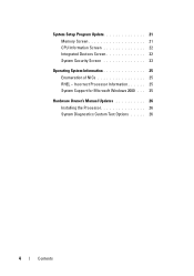
System Setup Program Update 21 Memory Screen 21 CPU Information Screen 22 Integrated Devices Screen 22 System Security Screen 23 Operating System Information 25 Enumeration of NICs 25 RHEL - Incorrect Processor Information 25 System Support for Microsoft Windows 2000 . . . 25 Hardware Owner's Manual Updates 26 Installing the Processor 26 System Diagnostics Custom Test Options . . . . . 26 4 Contents
System Setup Program Update 21 Memory Screen 21 CPU Information Screen 22 Integrated Devices Screen 22 System Security Screen 23 Operating System Information 25 Enumeration of NICs 25 RHEL - Incorrect Processor Information 25 System Support for Microsoft Windows 2000 . . . 25 Hardware Owner's Manual Updates 26 Installing the Processor 26 System Diagnostics Custom Test Options . . . . . 26 4 Contents
Information Update
Page 7
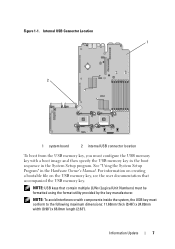
..." in the System Setup program. NOTE: To avoid interference with a boot image and then specify the USB memory key in the boot sequence in the Hardware Owner's Manual. Information Update 7 Figure 1-1. NOTE: USB keys that accompanied the USB memory key. For information on creating a bootable file on the USB memory key, see...
..." in the System Setup program. NOTE: To avoid interference with a boot image and then specify the USB memory key in the boot sequence in the Hardware Owner's Manual. Information Update 7 Figure 1-1. NOTE: USB keys that accompanied the USB memory key. For information on creating a bootable file on the USB memory key, see...
Information Update
Page 8
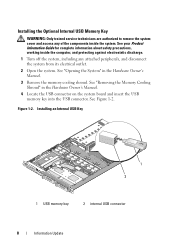
... including any attached peripherals, and disconnect the system from its electrical outlet. 2 Open the system. See "Opening the System" in the Hardware Owner's Manual. 4 Locate the USB connector on the system board and insert the USB memory key into the USB connector. See "Removing the Memory ...Cooling Shroud" in the Hardware Owner's Manual. 3 Remove the memory cooling shroud. Installing an Internal USB Key 1 2 1 USB memory key 2 internal USB connector 8 Information Update See...
... including any attached peripherals, and disconnect the system from its electrical outlet. 2 Open the system. See "Opening the System" in the Hardware Owner's Manual. 4 Locate the USB connector on the system board and insert the USB memory key into the USB connector. See "Removing the Memory ...Cooling Shroud" in the Hardware Owner's Manual. 3 Remove the memory cooling shroud. Installing an Internal USB Key 1 2 1 USB memory key 2 internal USB connector 8 Information Update See...
Information Update
Page 9
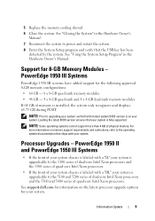
...version ensures that the latest system BIOS version is fully supported. For more than 4 GB of physical memory. See support.dell.com for information on memory support requirements and restrictions, refer to power and restart the system. 8 Enter the System ... 6 Close the system. See "Closing the System" in the Hardware Owner's Manual. NOTE: Some operating systems cannot support more information on the latest processor upgrade options for 8-GB Memory Modules - PowerEdge 1950 III Systems PowerEdge 1950 III systems have added support for the following approved 8-GB memory ...
...version ensures that the latest system BIOS version is fully supported. For more than 4 GB of physical memory. See support.dell.com for information on memory support requirements and restrictions, refer to power and restart the system. 8 Enter the System ... 6 Close the system. See "Closing the System" in the Hardware Owner's Manual. NOTE: Some operating systems cannot support more information on the latest processor upgrade options for 8-GB Memory Modules - PowerEdge 1950 III Systems PowerEdge 1950 III systems have added support for the following approved 8-GB memory ...
Information Update
Page 11
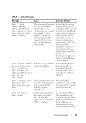
...the dedicated slot. See "Using the System Setup Program" in the Hardware Owner's Manual. For supported. controller slot. Memory Module Installation Guidelines" in the Hardware Owner's Manual for information on setting the order of boot devices. System Messages Message... but with reduced information, see "Troubleshooting System Memory" in the Hardware Owner's Manual. If the problem persists, see "General functionality. See "Installing a RAC Card" in the Hardware Owner's Manual. !!*** Error: Remote Access Controller initialization failure *** RAC virtual USB...
...the dedicated slot. See "Using the System Setup Program" in the Hardware Owner's Manual. For supported. controller slot. Memory Module Installation Guidelines" in the Hardware Owner's Manual for information on setting the order of boot devices. System Messages Message... but with reduced information, see "Troubleshooting System Memory" in the Hardware Owner's Manual. If the problem persists, see "General functionality. See "Installing a RAC Card" in the Hardware Owner's Manual. !!*** Error: Remote Access Controller initialization failure *** RAC virtual USB...
Information Update
Page 12
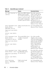
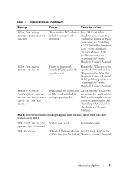
...see "Getting Help" in the dedicated PCIe connector. PCIe Training Error: Embedded device Faulty system board or riser board. Hardware Owner's Manual. Embedded device Expected Link Width is n Actual Link Width is n PCIe Degraded Link Width Error: Integrated device Expected ... Faulty or improperly Width Error: Slot n installed PCIe card in the Hardware Owner's Manual. is n Actual Link Width is faulty or improperly installed. See "Getting Help" in the Hardware Owner's Manual. Ensure that all detected during shadowing. faulty or improperly expansion card(s). ...
...see "Getting Help" in the dedicated PCIe connector. PCIe Training Error: Embedded device Faulty system board or riser board. Hardware Owner's Manual. Embedded device Expected Link Width is n Actual Link Width is n PCIe Degraded Link Width Error: Integrated device Expected ... Faulty or improperly Width Error: Slot n installed PCIe card in the Hardware Owner's Manual. is n Actual Link Width is faulty or improperly installed. See "Getting Help" in the Hardware Owner's Manual. Ensure that all detected during shadowing. faulty or improperly expansion card(s). ...
Information Update
Page 13
...Remote Access Controller cable error or incorrect card in the Hardware Owner's Manual. See "Installing a SAS Controller Daughter Card" in the Hardware Owner's Manual. See "Expansion Cards" in the Hardware Owner's Manual. operation honored. Hardware Owner's Manual. NOTE: All TPM information messages appear after the BMC ...option ROM has been loaded during POST. TPM Failure A Trusted Platform Module See "Getting Help" in the Hardware Owner's Manual. If the problem persists, see "Getting Help" in the RAC slot. Information Update 13 TPM configuration System now ...
...Remote Access Controller cable error or incorrect card in the Hardware Owner's Manual. See "Installing a SAS Controller Daughter Card" in the Hardware Owner's Manual. See "Expansion Cards" in the Hardware Owner's Manual. operation honored. Hardware Owner's Manual. NOTE: All TPM information messages appear after the BMC ...option ROM has been loaded during POST. TPM Failure A Trusted Platform Module See "Getting Help" in the Hardware Owner's Manual. If the problem persists, see "Getting Help" in the RAC slot. Information Update 13 TPM configuration System now ...
Information Update
Page 14
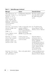
...by the n1 and n2. Please check the system event log! Warning! code update loaded See "Getting Help" in the Hardware Owner's Manual. Table 1-1. Check the SEL for a possible fault. See the applicable troubleshooting section in See "Troubleshooting Your System" in the... for any faulty components specified in Hardware Owner's Manual. System Memory" in the DIMMs are disabled: DIMM n1 n2 Total memory size is pending. for processor n Hardware Owner's Manual. 14 Information Update No micro Micro code update failed. System ...
...by the n1 and n2. Please check the system event log! Warning! code update loaded See "Getting Help" in the Hardware Owner's Manual. Table 1-1. Check the SEL for a possible fault. See the applicable troubleshooting section in See "Troubleshooting Your System" in the... for any faulty components specified in Hardware Owner's Manual. System Memory" in the DIMMs are disabled: DIMM n1 n2 Total memory size is pending. for processor n Hardware Owner's Manual. 14 Information Update No micro Micro code update failed. System ...
Information Update
Page 15
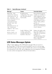
...event log (SEL). For information on the SEL and configuring system management settings, see the system documentation on the PowerEdge 1950 III system and the probable cause for each message. For more information on selected drive Faulty USB device, USB medium... See "General Memory Module Installation Guidelines" in the Hardware Owner's Manual. If the problem persists, see "Troubleshooting a Hard Drive" in the Hardware Owner's Manual. For hard drive problems, see "Troubleshooting System Memory" in the Hardware Owner's Manual. LCD Status Messages Update Table 1-2 lists updates to...
...event log (SEL). For information on the SEL and configuring system management settings, see the system documentation on the PowerEdge 1950 III system and the probable cause for each message. For more information on selected drive Faulty USB device, USB medium... See "General Memory Module Installation Guidelines" in the Hardware Owner's Manual. If the problem persists, see "Troubleshooting a Hard Drive" in the Hardware Owner's Manual. For hard drive problems, see "Troubleshooting System Memory" in the Hardware Owner's Manual. LCD Status Messages Update Table 1-2 lists updates to...
Information Update
Page 16
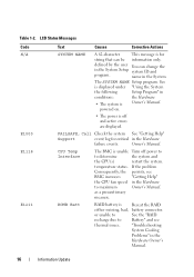
..."Using the System the following Setup Program" in the Hardware Owner's Manual. 16 Information Update If the problem Consequently, the persists, see thermal issues. "Troubleshooting System Cooling Problems" in conditions: the Hardware • The system is for critical in the Hardware to determine the system and the CPU(s) restart the... to See the "RAID recharge due to Battery" and see BMC increases "Getting Help" the CPU fan speed in the Hardware failure events. as a precautionary measure. Owner's Manual. defined by the user You can be information only.
..."Using the System the following Setup Program" in the Hardware Owner's Manual. 16 Information Update If the problem Consequently, the persists, see thermal issues. "Troubleshooting System Cooling Problems" in conditions: the Hardware • The system is for critical in the Hardware to determine the system and the CPU(s) restart the... to See the "RAID recharge due to Battery" and see BMC increases "Getting Help" the CPU fan speed in the Hardware failure events. as a precautionary measure. Owner's Manual. defined by the user You can be information only.
Information Update
Page 17
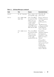
... reseat has reported a PCI the PCIe expansion parity error on a component that problem persists, resides in the specified PCIe slot. See "Getting Help" in the Hardware Owner's Manual. See "Expansion Card Risers" in the Hardware Owner's Manual. in the Hardware Owner's Manual.
... reseat has reported a PCI the PCIe expansion parity error on a component that problem persists, resides in the specified PCIe slot. See "Getting Help" in the Hardware Owner's Manual. See "Expansion Card Risers" in the Hardware Owner's Manual. in the Hardware Owner's Manual.
Information Update
Page 18
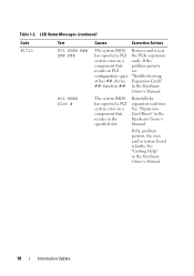
...PCIe expansion system error on a component that problem persists, resides in the specified slot. See "Getting Help" in the Hardware Owner's Manual. in the Hardware Owner's Manual. 18 Information Update The system BIOS has reported a PCI system error on a cards. If the component that resides ...PCI see configuration space "Troubleshooting at bus ##, device Expansion Cards" ##, function ##. See "Expansion Card Risers" in the Hardware Owner's Manual. If the problem persists, the riser card or system board is faulty. Table 1-2. Reinstall the expansion-card riser.
...PCIe expansion system error on a component that problem persists, resides in the specified slot. See "Getting Help" in the Hardware Owner's Manual. in the Hardware Owner's Manual. 18 Information Update The system BIOS has reported a PCI system error on a cards. If the component that resides ...PCI see configuration space "Troubleshooting at bus ##, device Expansion Cards" ##, function ##. See "Expansion Card Risers" in the Hardware Owner's Manual. If the problem persists, the riser card or system board is faulty. Table 1-2. Reinstall the expansion-card riser.
Information Update
Page 19
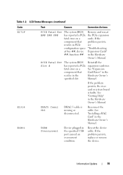
If the problem persists, see "Troubleshooting Expansion Cards" in the Hardware Owner's Manual. See "Getting Help" in the Hardware Owner's Manual. USB# Overcurrent Device plugged in the Hardware Owner's Manual. If the problem persists, replace or remove the device. See "Installing a RAC Card" in the specified ... cable. PCIE Fatal Err Slot # The system BIOS has reported a PCIe fatal error on a component that resides in the Hardware Owner's Manual. Remove and reseat the PCIe expansion cards. Reinstall the expansion-card riser. If the problem persists, the riser card or system...
If the problem persists, see "Troubleshooting Expansion Cards" in the Hardware Owner's Manual. See "Getting Help" in the Hardware Owner's Manual. USB# Overcurrent Device plugged in the Hardware Owner's Manual. If the problem persists, replace or remove the device. See "Installing a RAC Card" in the specified ... cable. PCIE Fatal Err Slot # The system BIOS has reported a PCIe fatal error on a component that resides in the Hardware Owner's Manual. Remove and reseat the PCIe expansion cards. Reinstall the expansion-card riser. If the problem persists, the riser card or system...


