

Installing a SATA Optical Drive
Page 3
...See "Removing a SAS Controller Daughter Card" in your Hardware Owner's Manual. 4 PowerEdge 1950 systems only: Disconnect and remove the SAS controller daughter card. WARNING: Only trained service... Manual. 3 Remove the system cover. See your Hardware Owner's Manual. 5 Disconnect the data and power cables from the electrical outlet. 2 Remove the bezel. Removing an Existing Optical Drive - All Systems 1... the back of the system. Installing a SATA Optical Drive These instructions apply to Dell™ PowerEdge™ systems to remove the system cover and access any of the peripheral bay ...
...See "Removing a SAS Controller Daughter Card" in your Hardware Owner's Manual. 4 PowerEdge 1950 systems only: Disconnect and remove the SAS controller daughter card. WARNING: Only trained service... Manual. 3 Remove the system cover. See your Hardware Owner's Manual. 5 Disconnect the data and power cables from the electrical outlet. 2 Remove the bezel. Removing an Existing Optical Drive - All Systems 1... the back of the system. Installing a SATA Optical Drive These instructions apply to Dell™ PowerEdge™ systems to remove the system cover and access any of the peripheral bay ...

Installing a SATA Optical Drive
Page 5
...into the tray until the pins on the carrier align with the holes in the installation kit must be used with PowerEdge 1950 systems. If you are replacing an existing optical drive, do not reuse the interposer board attached to the tray. Replacing ...the Optical Drive in a PowerEdge 2950 or 2970 System 2 1 3 4 5 6 7 1 optical drive 3 interposer 5 SATA power cable 7 optical drive carrier 2 interposer release latch 4 SATA cable 6 carrier latch Replacing a PowerEdge 1950 Optical Drive NOTE: The replacement drive tray provided in the side of the...
...into the tray until the pins on the carrier align with the holes in the installation kit must be used with PowerEdge 1950 systems. If you are replacing an existing optical drive, do not reuse the interposer board attached to the tray. Replacing ...the Optical Drive in a PowerEdge 2950 or 2970 System 2 1 3 4 5 6 7 1 optical drive 3 interposer 5 SATA power cable 7 optical drive carrier 2 interposer release latch 4 SATA cable 6 carrier latch Replacing a PowerEdge 1950 Optical Drive NOTE: The replacement drive tray provided in the side of the...

Installing a SATA Optical Drive
Page 6
... chipset shroud and insert the cable into position. 2 Connect the SATA cable (the end with a cable provided in a PowerEdge 1950 Drive Tray 2 3 1 4 5 1 optical drive 3 SATA power cable 5 optical drive carrier 2 SATA cable 4 carrier latch Installing the SATA Optical Drive - Figure 1-2. c Connect the cable to... the power supply bays. PowerEdge 1950 1 Insert the optical drive tray into the system until it is fully inserted and locked into the cable path on top of the optical drive. 3 Connect the branching power cable to the SATA_A connector on the ...
... chipset shroud and insert the cable into position. 2 Connect the SATA cable (the end with a cable provided in a PowerEdge 1950 Drive Tray 2 3 1 4 5 1 optical drive 3 SATA power cable 5 optical drive carrier 2 SATA cable 4 carrier latch Installing the SATA Optical Drive - Figure 1-2. c Connect the cable to... the power supply bays. PowerEdge 1950 1 Insert the optical drive tray into the system until it is fully inserted and locked into the cable path on top of the optical drive. 3 Connect the branching power cable to the SATA_A connector on the ...

Installing a SATA Optical Drive
Page 7
... system. Installing a SATA Optical Drive 7 PowerEdge 2970 or 2950 1 Insert the optical drive tray into the system until it is fully inserted and locked into position. 2 Connect the SATA cable (the end with the branching power cable) to the back of the optical drive... Drive - SATA Cable Routing in your Hardware Owner's Manual. 7 Reconnect the system to the power supply connector. See "SAS Controller Daughter Card" in the PowerEdge 1950 2 1 3 4 6 5 1 SATA data cable 3 chipset shroud 5 SATA power cable 2 SATA_A connector on the system and attached peripherals. Figure 1-3.
... system. Installing a SATA Optical Drive 7 PowerEdge 2970 or 2950 1 Insert the optical drive tray into the system until it is fully inserted and locked into position. 2 Connect the SATA cable (the end with the branching power cable) to the back of the optical drive... Drive - SATA Cable Routing in your Hardware Owner's Manual. 7 Reconnect the system to the power supply connector. See "SAS Controller Daughter Card" in the PowerEdge 1950 2 1 3 4 6 5 1 SATA data cable 3 chipset shroud 5 SATA power cable 2 SATA_A connector on the system and attached peripherals. Figure 1-3.

Installing a SATA Optical Drive
Page 8
... bracket toward the front of the system until the bracket detaches from the chassis slots. 6 Route the SATA cable in the cable channel in the PowerEdge 2950 and 2970 1 2 3 4 5 1 SATA_B connector on the system board. SATA Cable Routing in the right wall of the cable retention ...8 Bend the cable behind the central riser and connect the cable to the SATA_B connector on system board 2 cable retention bracket 3 SATA data cable 4 SATA power cable 5 optical drive 8 Installing a SATA Optical Drive Figure 1-4. 4 Remove the cooling shroud. See Figure 1-4. 7 Route the SATA cable along the top...
... bracket toward the front of the system until the bracket detaches from the chassis slots. 6 Route the SATA cable in the cable channel in the PowerEdge 2950 and 2970 1 2 3 4 5 1 SATA_B connector on the system board. SATA Cable Routing in the right wall of the cable retention ...8 Bend the cable behind the central riser and connect the cable to the SATA_B connector on system board 2 cable retention bracket 3 SATA data cable 4 SATA power cable 5 optical drive 8 Installing a SATA Optical Drive Figure 1-4. 4 Remove the cooling shroud. See Figure 1-4. 7 Route the SATA cable along the top...

Installing a SATA Optical Drive
Page 9
See "Closing the System" in your Hardware Owner's Manual. 11 Reconnect the system to power and turn on the system board. See Figure 1-5. - For a PowerEdge 1900 system, connect to the CD/TBU connector on the system backplane. See "Replacing the Center Fan ... bracket and connect the cable to the power supply as follows: - For a PowerEdge 2900 system, connect to an available power supply cable. 5 Replace the center fan bracket. See Figure 1-5. - For a PowerEdge 2900, use the SATA_D connector. Installing the SATA Optical Drive - For a PowerEdge 1900, use the SATA_B connector. -...
See "Closing the System" in your Hardware Owner's Manual. 11 Reconnect the system to power and turn on the system board. See Figure 1-5. - For a PowerEdge 1900 system, connect to the CD/TBU connector on the system backplane. See "Replacing the Center Fan ... bracket and connect the cable to the power supply as follows: - For a PowerEdge 2900 system, connect to an available power supply cable. 5 Replace the center fan bracket. See Figure 1-5. - For a PowerEdge 2900, use the SATA_D connector. Installing the SATA Optical Drive - For a PowerEdge 1900, use the SATA_B connector. -...

Installing a SATA Optical Drive
Page 10
See "Closing the System" in a PowerEdge 2900 or 1900 3 2 4 5 1 1 optical drive 3 SATA data cable 5 SATA power connector on SAS backplane (PowerEdge 2900 only) 2 SATA power cable 4 SATA connector on the system and attached peripherals. 10 Installing a SATA Optical Drive SATA Cable Routing in your Hardware Owner's Manual. 10 Reconnect the system to power and turn on system board 8 Reconnect the cables to the SAS controller daughter card. 9 Close the system. Figure 1-5.
See "Closing the System" in a PowerEdge 2900 or 1900 3 2 4 5 1 1 optical drive 3 SATA data cable 5 SATA power connector on SAS backplane (PowerEdge 2900 only) 2 SATA power cable 4 SATA connector on the system and attached peripherals. 10 Installing a SATA Optical Drive SATA Cable Routing in your Hardware Owner's Manual. 10 Reconnect the system to power and turn on system board 8 Reconnect the cables to the SAS controller daughter card. 9 Close the system. Figure 1-5.
Information Update
Page 3
... Replacement - Safeguarding Encrypted Data 10 System Message Update 10 LCD Status Messages Update 15 Contents 3 PowerEdge 1950 III Systems 9 Processor Upgrades - Contents Non-Optimal Memory Configurations 5 PowerEdge 1950 III - New System Features 5 New Performance Features 5 New High-Efficiency Power Supply and Power Monitoring Features 5 New I/O and Storage Features 6 New Security Features 6 Optional Internal USB Memory Key...
... Replacement - Safeguarding Encrypted Data 10 System Message Update 10 LCD Status Messages Update 15 Contents 3 PowerEdge 1950 III Systems 9 Processor Upgrades - Contents Non-Optimal Memory Configurations 5 PowerEdge 1950 III - New System Features 5 New Performance Features 5 New High-Efficiency Power Supply and Power Monitoring Features 5 New I/O and Storage Features 6 New Security Features 6 Optional Internal USB Memory Key...
Information Update
Page 5
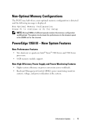
... across workloads. • Baseboard Management Control (BMC) power monitoring monitors current, voltage, and power utilization in the DIMM set for Setup NOTE: Mixing DIMMs of different speeds renders the memory configuration non6Hoptimal. The system clocks down the performance to continue or F2 for the channel. PowerEdge 1950 III - Information Update 5 Non-Optimal Memory Configurations...
... across workloads. • Baseboard Management Control (BMC) power monitoring monitors current, voltage, and power utilization in the DIMM set for Setup NOTE: Mixing DIMMs of different speeds renders the memory configuration non6Hoptimal. The system clocks down the performance to continue or F2 for the channel. PowerEdge 1950 III - Information Update 5 Non-Optimal Memory Configurations...
Information Update
Page 9
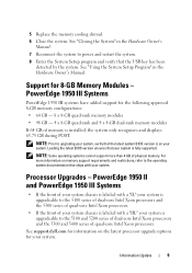
...core Intel Xeon processors. • If the front of your system chassis is fully supported. See support.dell.com for the following approved 8-GB memory configurations: • 64 GB - 8 x 8-GB quad-rank...system only recognizes and displays 63.75 GB during POST. Processor Upgrades - PowerEdge 1950 II and PowerEdge 1950 III Systems • If the front of your system chassis is labeled ... Some operating systems cannot support more information on memory support requirements and restrictions, refer to power and restart the system. 8 Enter the System Setup program and verify that ships with a...
...core Intel Xeon processors. • If the front of your system chassis is fully supported. See support.dell.com for the following approved 8-GB memory configurations: • 64 GB - 8 x 8-GB quad-rank...system only recognizes and displays 63.75 GB during POST. Processor Upgrades - PowerEdge 1950 II and PowerEdge 1950 III Systems • If the front of your system chassis is labeled ... Some operating systems cannot support more information on memory support requirements and restrictions, refer to power and restart the system. 8 Enter the System Setup program and verify that ships with a...
Information Update
Page 16
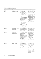
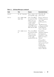
... Owner's Manual. 16 Information Update LCD Status Messages Code N/A E1000 E1118 E1211 Text Causes Corrective Actions SYSTEM NAME A 62-character This message is off power to to determine the system and the CPU(s) restart the system. CPU Temp Interface The BMC is Reseat the RAID either missing, bad, battery connector...See the "RAID recharge due to maximum Owner's Manual. Owner's Manual. Table 1-2. as a precautionary measure. defined by the user You can be information only. powered on. • The power is for critical in the System Setup system ID and program.
... Owner's Manual. 16 Information Update LCD Status Messages Code N/A E1000 E1118 E1211 Text Causes Corrective Actions SYSTEM NAME A 62-character This message is off power to to determine the system and the CPU(s) restart the system. CPU Temp Interface The BMC is Reseat the RAID either missing, bad, battery connector...See the "RAID recharge due to maximum Owner's Manual. Owner's Manual. Table 1-2. as a precautionary measure. defined by the user You can be information only. powered on. • The power is for critical in the System Setup system ID and program.
Information Update
Page 17
power source. Reinstall the expansion-card riser. See "Getting Help" in the Hardware Owner's Manual. If the problem persists, the riser card or system board is .... If the component that resides in the specified PCIe slot. Table 1-2. LCD Status Messages (continued) Code E1625 E1711 Text Causes Corrective Actions PS AC Current Power source is faulty.
power source. Reinstall the expansion-card riser. See "Getting Help" in the Hardware Owner's Manual. If the problem persists, the riser card or system board is .... If the component that resides in the specified PCIe slot. Table 1-2. LCD Status Messages (continued) Code E1625 E1711 Text Causes Corrective Actions PS AC Current Power source is faulty.
Information Update
Page 21
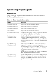
... set to Disabled, the system can support Non-Uniform Memory architecture (NUMA) (asymmetric) memory configurations. Enables or disables the low power mode of system memory. NOTE: The Node Interleaving field must be set to conserve energy. Specifies whether system memory tests are Enabled... System Memory Type System Memory Speed Video Memory System Memory Testing Redundant Memory (Disabled default) Node Interleaving (Disabled default) Low Power Mode (Disabled default) Description Displays the amount of memory on each DIMM is enabled. Displays the amount of video memory....
... set to Disabled, the system can support Non-Uniform Memory architecture (NUMA) (asymmetric) memory configurations. Enables or disables the low power mode of system memory. NOTE: The Node Interleaving field must be set to conserve energy. Specifies whether system memory tests are Enabled... System Memory Type System Memory Speed Video Memory System Memory Testing Redundant Memory (Disabled default) Node Interleaving (Disabled default) Low Power Mode (Disabled default) Description Displays the amount of memory on each DIMM is enabled. Displays the amount of video memory....

Information Update
Page 22
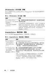
...Screen Table 1-5 lists new Integrated Devices screen options. When set to the operating system. Table 1-4. CPU Information Screen Option Demand-Based Power Management (Enabled default) Description NOTE: Check your operating system documentation to All ports On (the default value). Table 1-5. If any ...of the Advanced Configuration (Disabled default) and Power Interface (ACPI) 3.0b specification. NOTE: You can only enable the internal USB port if the User Accessible USB Ports option on...
...Screen Table 1-5 lists new Integrated Devices screen options. When set to the operating system. Table 1-4. CPU Information Screen Option Demand-Based Power Management (Enabled default) Description NOTE: Check your operating system documentation to All ports On (the default value). Table 1-5. If any ...of the Advanced Configuration (Disabled default) and Power Interface (ACPI) 3.0b specification. NOTE: You can only enable the internal USB port if the User Accessible USB Ports option on...

Information Update
Page 45
内存屏幕 表 1-3 列出了 Memory Information 表 1-3. Memory Information 选项 System Memory Size System Memory Type System Memory Speed Video Memory System Memory Testing Redundant Memory Disabled Node Interleaving Disabled Low Power Mode Disabled Enabled Disabled Spare Mode DIMM Node Interleaving Enabled Disabled NUMA Node Interleaving Disabled Disabled Enabled 信息更新 45
内存屏幕 表 1-3 列出了 Memory Information 表 1-3. Memory Information 选项 System Memory Size System Memory Type System Memory Speed Video Memory System Memory Testing Redundant Memory Disabled Node Interleaving Disabled Low Power Mode Disabled Enabled Disabled Spare Mode DIMM Node Interleaving Enabled Disabled NUMA Node Interleaving Disabled Disabled Enabled 信息更新 45
Information Update
Page 46
... 表 1-4. CPU Information(CPU 选项 说明 Demand-Based Power Management Enabled CPU CPU CPU Disabled Integrated Devices 表 1-5 Integrated Devices 表 1-5. Integrated Devices 选项 说明 Internal USB Port (内部 USB ...
... 表 1-4. CPU Information(CPU 选项 说明 Demand-Based Power Management Enabled CPU CPU CPU Disabled Integrated Devices 表 1-5 Integrated Devices 表 1-5. Integrated Devices 选项 说明 Internal USB Port (内部 USB ...

Information Update
Page 132
Memory Information 説明 System Memory Size System Memory Type System Memory Speed Video Memory System Memory Testing Enabled Disabled Redundant Memory Disabled) Spare Mode DIMM の第 1 Node Interleaving Node Interleaving Disabled) NUMA(Non-Uniform Memory Architecture Node Interleaving Disabled Low Power Mode Disabled) Low Power Mode Disabled Enabled 132 Memory Information 1-3 表 1-3.
Memory Information 説明 System Memory Size System Memory Type System Memory Speed Video Memory System Memory Testing Enabled Disabled Redundant Memory Disabled) Spare Mode DIMM の第 1 Node Interleaving Node Interleaving Disabled) NUMA(Non-Uniform Memory Architecture Node Interleaving Disabled Low Power Mode Disabled) Low Power Mode Disabled Enabled 132 Memory Information 1-3 表 1-3.

Information Update
Page 133
CPU Information(CPU Demand-Based Power Management Enabled) 説明 メモ:OS CPU OS CPU OS CPU が 1 Disabled Integrated Devices Integrated Devices 1-5 表 1-5. CPU Information(CPU Demand-Based Power Management 1-4 表 1-4. Integrated Devices 説明 Internal USB Port USB On) USB User Accessible USB Ports USB ポ All ports On(すべて きます。 133
CPU Information(CPU Demand-Based Power Management Enabled) 説明 メモ:OS CPU OS CPU OS CPU が 1 Disabled Integrated Devices Integrated Devices 1-5 表 1-5. CPU Information(CPU Demand-Based Power Management 1-4 表 1-4. Integrated Devices 説明 Internal USB Port USB On) USB User Accessible USB Ports USB ポ All ports On(すべて きます。 133

Information Update
Page 158
System Setup 표 1-3은 Memory Information 표 1-3 옵션 System Memory Size System Memory Type System Memory Speed Video Memory System Memory Testing Redundant Memory Disabled Node Interleaving Disabled Low Power Mode Disabled Enabled Disabled Spare Mode DIMM Node Interleaving Enabled Disabled NUMA (Non-Uniform Memory Architecture Node Interleaving Disabled Disabled Enabled 158
System Setup 표 1-3은 Memory Information 표 1-3 옵션 System Memory Size System Memory Type System Memory Speed Video Memory System Memory Testing Redundant Memory Disabled Node Interleaving Disabled Low Power Mode Disabled Enabled Disabled Spare Mode DIMM Node Interleaving Enabled Disabled NUMA (Non-Uniform Memory Architecture Node Interleaving Disabled Disabled Enabled 158
Information Update
Page 159
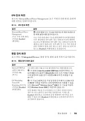
CPU 표 1-4는 Demand-Based Power Management 표 1-4. CPU 옵션 Demand-Based Power Management Enabled 설명 CPU CPU CPU Disabled 표 1-5에는 새 Integrated Devices 표 1-5 옵션 설명 Internal USB Port (내부 USB ...
CPU 표 1-4는 Demand-Based Power Management 표 1-4. CPU 옵션 Demand-Based Power Management Enabled 설명 CPU CPU CPU Disabled 표 1-5에는 새 Integrated Devices 표 1-5 옵션 설명 Internal USB Port (내부 USB ...


