

Installing a SATA Optical Drive
Page 5
...interposer release latch 4 SATA cable 6 carrier latch Replacing a PowerEdge 1950 Optical Drive NOTE: The replacement drive tray provided in the installation kit must be used with the holes in the side of the drive. Installing a SATA Optical Drive 5 Release the rails to attach the drive to the old drive. Figure 1-1. ...Spread the side rails of the replacement drive tray and insert the back end of the SATA optical drive into the tray until the pins on the carrier align with PowerEdge 1950 systems. If you are replacing an existing optical drive, do not...
...interposer release latch 4 SATA cable 6 carrier latch Replacing a PowerEdge 1950 Optical Drive NOTE: The replacement drive tray provided in the installation kit must be used with the holes in the side of the drive. Installing a SATA Optical Drive 5 Release the rails to attach the drive to the old drive. Figure 1-1. ...Spread the side rails of the replacement drive tray and insert the back end of the SATA optical drive into the tray until the pins on the carrier align with PowerEdge 1950 systems. If you are replacing an existing optical drive, do not...
Hardware Owner's Manual (PDF)
Page 56
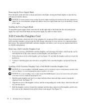
... are removing a SAS RAID controller daughter card, disconnect the battery cable from the card by its socket. to clear the bay, and remove from the rails. NOTICE: If you have completed installing the card. 1 Hold the metal daughter card tray by releasing the tab on the cable connector on the daughter... on the chassis, then lower the card tray onto the chassis. 3 Slide the daughter card tray towards the hard drives. 3 Continue to hold the guide rails outward as you to set up any internal hard drives in a non-redundant configuration.
... are removing a SAS RAID controller daughter card, disconnect the battery cable from the card by its socket. to clear the bay, and remove from the rails. NOTICE: If you have completed installing the card. 1 Hold the metal daughter card tray by releasing the tab on the cable connector on the daughter... on the chassis, then lower the card tray onto the chassis. 3 Slide the daughter card tray towards the hard drives. 3 Continue to hold the guide rails outward as you to set up any internal hard drives in a non-redundant configuration.

Hardware Owner's Manual (PDF)
Page 78
... interposer card: a Viewing the hard drive carrier from the carrier. See Figure 3-19. 2 Viewing the assembly as shown in the carrier rail. 2 Remove the four screws from the slide rails on the hard-drive carrier and separate the hard drive from the rear, locate the release lever on the hard drive carrier... Figure 3-19, align the bottom rear screw hole on the hard drive with the hole labeled "SAS" on the left end away from the carrier rail to release the connector.
... interposer card: a Viewing the hard drive carrier from the carrier. See Figure 3-19. 2 Viewing the assembly as shown in the carrier rail. 2 Remove the four screws from the slide rails on the hard-drive carrier and separate the hard drive from the rear, locate the release lever on the hard drive carrier... Figure 3-19, align the bottom rear screw hole on the hard drive with the hole labeled "SAS" on the left end away from the carrier rail to release the connector.

Hardware Owner's Manual (PDF)
Page 81
... 3-21. c Push the bottom end of the card towards the hard drive until the latch on the card bracket clicks into the inside top carrier rail so that the tabs on the interposer card bracket attach to the slots on the inside of the carrier... rail. 4 Attach the interposer card to the rear of the SATA hard drive: a Angle the top of the interposer card into place. See Figure 3-21. b Rotate ...
... 3-21. c Push the bottom end of the card towards the hard drive until the latch on the card bracket clicks into the inside top carrier rail so that the tabs on the interposer card bracket attach to the slots on the inside of the carrier... rail. 4 Attach the interposer card to the rear of the SATA hard drive: a Angle the top of the interposer card into place. See Figure 3-21. b Rotate ...

Getting Started Guide
Page 8
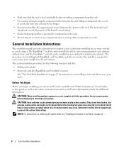
..., and Monitor Connect the keyboard, mouse, and monitor (optional). Be sure to tighten the screws (if any) on installing your system in a rack. Installing the Rail and System in a Rack Install the system in the rack once you simultaneously connect two monitors to the system, using the front and rear video...
..., and Monitor Connect the keyboard, mouse, and monitor (optional). Be sure to tighten the screws (if any) on installing your system in a rack. Installing the Rail and System in a Rack Install the system in the rack once you simultaneously connect two monitors to the system, using the front and rear video...

Rack Installation Guide
Page 5
...: Rack Mounting of Systems 5 General Installation Instructions 6 Before You Begin 6 Important Safety Information 7 Rack Requirements for VersaRails 7 Rack Stabilizer Feet 7 Recommended Tools and Supplies 7 Sliding Rails Rack Kit Contents 8 Static Rails Rack Kit Contents 9 Installation Tasks 10 Removing the Rack Doors 10 Marking the Rack 10 Configuring the Sliding...
...: Rack Mounting of Systems 5 General Installation Instructions 6 Before You Begin 6 Important Safety Information 7 Rack Requirements for VersaRails 7 Rack Stabilizer Feet 7 Recommended Tools and Supplies 7 Sliding Rails Rack Kit Contents 8 Static Rails Rack Kit Contents 9 Installation Tasks 10 Removing the Rack Doors 10 Marking the Rack 10 Configuring the Sliding...

Rack Installation Guide
Page 6
2 Two-Post Rack Installation 27 Safety Instructions 27 SAFETY: Rack Mounting of Systems 27 Before You Begin 28 Important Safety Information 28 Recommended Tools and Supplies 28 Rack Kit Contents 29 Installation Tasks 30 Marking the Rack 30 Universal-Hole Spacing Racks 30 Wide-Hole Spacing Racks 31 Installing the Mounting Rails 32 Center-Mount Installation 32 Flush-Mount Installation 33 Installing Chassis Static Rail Modules 36 Installing the System in the Rack 37 Removing the System From the Rack 37 Index 39 4 Contents
2 Two-Post Rack Installation 27 Safety Instructions 27 SAFETY: Rack Mounting of Systems 27 Before You Begin 28 Important Safety Information 28 Recommended Tools and Supplies 28 Rack Kit Contents 29 Installation Tasks 30 Marking the Rack 30 Universal-Hole Spacing Racks 30 Wide-Hole Spacing Racks 31 Installing the Mounting Rails 32 Center-Mount Installation 32 Flush-Mount Installation 33 Installing Chassis Static Rail Modules 36 Installing the System in the Rack 37 Removing the System From the Rack 37 Index 39 4 Contents
Rack Installation Guide
Page 8
... information. They do not have brakes. Retract the leveling feet when relocating the rack cabinet. NOTE: For instructions on installing a static rails kit in a two-post rack.) Before You Begin Before you begin installing your system in the rack, carefully read "Safety Instructions," ...as the safety instructions found in a rack. This section includes procedures for the following four-post rack kits: • Sliding rails rack kit • Static rails rack kit (RapidRails and VersaRails versions) (See "Two-Post Rack Installation" on page 27 for instructions on installing the system itself...
... information. They do not have brakes. Retract the leveling feet when relocating the rack cabinet. NOTE: For instructions on installing a static rails kit in a two-post rack.) Before You Begin Before you begin installing your system in the rack, carefully read "Safety Instructions," ...as the safety instructions found in a rack. This section includes procedures for the following four-post rack kits: • Sliding rails rack kit • Static rails rack kit (RapidRails and VersaRails versions) (See "Two-Post Rack Installation" on page 27 for instructions on installing the system itself...

Rack Installation Guide
Page 10
Sliding Rails Rack Kit Contents • One pair of slide assemblies (convertible to RapidRails or VersaRails configuration) • One cable-management arm • One tray • One ... screws described in illustrations and in procedural steps are identified by size and number of threads per inch is identified as a 10-32 screw. Sliding Rails Rack Kit Contents 1 6 5 2 3 4 1 tray 4 tie wraps 2 slide assemblies (2) 5 status indicator cable (if applicable) 3 10-32 x 0.5-inch flange-head Phillips screws (8) (VersaRails configuration only) 6 cable-management...
Sliding Rails Rack Kit Contents • One pair of slide assemblies (convertible to RapidRails or VersaRails configuration) • One cable-management arm • One tray • One ... screws described in illustrations and in procedural steps are identified by size and number of threads per inch is identified as a 10-32 screw. Sliding Rails Rack Kit Contents 1 6 5 2 3 4 1 tray 4 tie wraps 2 slide assemblies (2) 5 status indicator cable (if applicable) 3 10-32 x 0.5-inch flange-head Phillips screws (8) (VersaRails configuration only) 6 cable-management...

Rack Installation Guide
Page 11
... of threads per inch is identified as a 10-32 screw. Static Rails Rack Kit Contents 1 3 2 L FRONT 1 10-32 x 0.5-inch flange-head 2 static mounting rails (2) Phillips screws (8) (VersaRails kits only) 3 chassis static rail modules (2) Four-Post Rack Installation 9 For example, a #10 Phillips...-head screw with either VersaRails brackets or RapidRails brackets. • One pair of chassis static rail modules • 10-32 x 0.5-inch flange-head Phillips screws (8) (VersaRails kits only) • Releasable tie wraps (2) (not shown...
... of threads per inch is identified as a 10-32 screw. Static Rails Rack Kit Contents 1 3 2 L FRONT 1 10-32 x 0.5-inch flange-head 2 static mounting rails (2) Phillips screws (8) (VersaRails kits only) 3 chassis static rail modules (2) Four-Post Rack Installation 9 For example, a #10 Phillips...-head screw with either VersaRails brackets or RapidRails brackets. • One pair of chassis static rail modules • 10-32 x 0.5-inch flange-head Phillips screws (8) (VersaRails kits only) • Releasable tie wraps (2) (not shown...

Rack Installation Guide
Page 12
... lines and numbers in 1-U increments. If you want, you can make a note of vertical space for the front and back vertical rails (see Figure 1-3). Rack cabinets that meet EIA-310 standards have round or square holes. CAUTION: Store the two doors where they will... in their numbered order: 1 Removing the rack doors 2 Marking the rack 3 Configuring the sliding rail assemblies (sliding rail kits only) 4 Installing chassis static rail modules (static rail kits only) 5 Installing the mounting rails in the rack 6 Installing the system in the rack 7 Installing the tray and cable-management arm ...
... lines and numbers in 1-U increments. If you want, you can make a note of vertical space for the front and back vertical rails (see Figure 1-3). Rack cabinets that meet EIA-310 standards have round or square holes. CAUTION: Store the two doors where they will... in their numbered order: 1 Removing the rack doors 2 Marking the rack 3 Configuring the sliding rail assemblies (sliding rail kits only) 4 Installing chassis static rail modules (static rail kits only) 5 Installing the mounting rails in the rack 6 Installing the system in the rack 7 Installing the tray and cable-management arm ...

Rack Installation Guide
Page 13
...inches) above the top hole). This mark or piece of tape indicates where the system's upper edge will be located on the rack's front vertical rails where you want to locate the bottom of the narrowest metal area between holes (marked with a horizontal line on some rack cabinets-see Figure 1-4). ... just above the original mark you made (or count up three holes in a rack that meets EIA-310 standards) and mark the rack's front vertical rails with a felt-tipped pen or masking tape (if you are installing in the rack. Four-Post Rack Installation 11 Figure 1-3. The bottom of each 1-U...
...inches) above the top hole). This mark or piece of tape indicates where the system's upper edge will be located on the rack's front vertical rails where you want to locate the bottom of the narrowest metal area between holes (marked with a horizontal line on some rack cabinets-see Figure 1-4). ... just above the original mark you made (or count up three holes in a rack that meets EIA-310 standards) and mark the rack's front vertical rails with a felt-tipped pen or masking tape (if you are installing in the rack. Four-Post Rack Installation 11 Figure 1-3. The bottom of each 1-U...

Rack Installation Guide
Page 14
Figure 1-4. Marking the Vertical Rails 1 1 marks on vertical rail (2) 12 Four-Post Rack Installation
Figure 1-4. Marking the Vertical Rails 1 1 marks on vertical rail (2) 12 Four-Post Rack Installation

Rack Installation Guide
Page 15
...screws to attach it to the vertical rail. Changing the Position of the bracket determines whether the rail assembly is used as a RapidRail or a VersaRail. Figure 1-5. The RapidRail side of the rail. To rotate the mounting bracket and change the mounting rails from RapidRails to VersaRails (see Figure...the opposite direction on the rotating mounting bracket. 2 Rotate the bracket and slide it to the vertical rail. Configuring the Sliding Rail Assemblies (Sliding Rail Kits Only) The sliding rail assembly has a rotating mounting bracket at each end of the bracket has a hook and a latch that...
...screws to attach it to the vertical rail. Changing the Position of the bracket determines whether the rail assembly is used as a RapidRail or a VersaRail. Figure 1-5. The RapidRail side of the rail. To rotate the mounting bracket and change the mounting rails from RapidRails to VersaRails (see Figure...the opposite direction on the rotating mounting bracket. 2 Rotate the bracket and slide it to the vertical rail. Configuring the Sliding Rail Assemblies (Sliding Rail Kits Only) The sliding rail assembly has a rotating mounting bracket at each end of the bracket has a hook and a latch that...

Rack Installation Guide
Page 16
...or remove the chassis static rail modules from the chassis. 1 To install a rail module, locate the three keyhole slots on the rail module and the corresponding shoulder screws on the release latch, then slide the rail forward and remove the rail module from the chassis,... module towards the back of the system. 3 Repeat steps 1 and 2 to install the other rail module. To remove a rail module from the chassis. Installing and Removing Static Rail Chassis Modules 1 5 2 4 3 1 keyhole slots (6) 4 rail modules (2) 2 shoulder screws (6) 5 system 3 release latch 14 Four-Post Rack Installation
...or remove the chassis static rail modules from the chassis. 1 To install a rail module, locate the three keyhole slots on the rail module and the corresponding shoulder screws on the release latch, then slide the rail forward and remove the rail module from the chassis,... module towards the back of the system. 3 Repeat steps 1 and 2 to install the other rail module. To remove a rail module from the chassis. Installing and Removing Static Rail Chassis Modules 1 5 2 4 3 1 keyhole slots (6) 4 rail modules (2) 2 shoulder screws (6) 5 system 3 release latch 14 Four-Post Rack Installation

Rack Installation Guide
Page 17
... (or numbered locations) on the vertical rails. Installing the Mounting Rails in "Marking the Rack" (see Figure 1-7). Installing RapidRails Mounting Rails 1 At the front of the rack cabinet, position one of rack 1 mounting hooks (2) 2 push buttons (2) 3 mounting rails (2) Four-Post Rack Installation 15 The... top mounting hook on the front mounting-bracket flange should enter the top hole between the marks or tape you made on the vertical rails in the Rack NOTE: The following instructions apply...
... (or numbered locations) on the vertical rails. Installing the Mounting Rails in "Marking the Rack" (see Figure 1-7). Installing RapidRails Mounting Rails 1 At the front of the rack cabinet, position one of rack 1 mounting hooks (2) 2 push buttons (2) 3 mounting rails (2) Four-Post Rack Installation 15 The... top mounting hook on the front mounting-bracket flange should enter the top hole between the marks or tape you made on the vertical rails in the Rack NOTE: The following instructions apply...

Rack Installation Guide
Page 18
... the back of the cabinet, pull back on the mounting-bracket flange until the mounting holes align with their respective holes on the back vertical rail. 4 Install two 10-32 x 0.5-inch flange-head Phillips screws in the upper and lower holes in "Marking the Rack" (see Figure 1-7). 3 At the back of.... The three holes on the front of the mounting-bracket flange should align with the holes between the marks you made on the front vertical rail. 2 Install two 10-32 x 0.5-inch flange-head Phillips screws in the upper and lower holes in the mountingbracket flange to secure the mounting...
... the back of the cabinet, pull back on the mounting-bracket flange until the mounting holes align with their respective holes on the back vertical rail. 4 Install two 10-32 x 0.5-inch flange-head Phillips screws in the upper and lower holes in "Marking the Rack" (see Figure 1-7). 3 At the back of.... The three holes on the front of the mounting-bracket flange should align with the holes between the marks you made on the front vertical rail. 2 Install two 10-32 x 0.5-inch flange-head Phillips screws in the upper and lower holes in the mountingbracket flange to secure the mounting...

Rack Installation Guide
Page 19
Installing VersaRails Mounting Rails 1 2 3 front of rack 1 mounting-bracket flange 2 10-32 x 0.5-inch flange-head 3 mounting rails (2) Phillips screws (4 per mounting rail) Four-Post Rack Installation 17 Figure 1-8.
Installing VersaRails Mounting Rails 1 2 3 front of rack 1 mounting-bracket flange 2 10-32 x 0.5-inch flange-head 3 mounting rails (2) Phillips screws (4 per mounting rail) Four-Post Rack Installation 17 Figure 1-8.

Rack Installation Guide
Page 20
... rack front panel to secure the slide assemblies to the rack. 18 Four-Post Rack Installation See "Installing the Tray and Cable-Management Arm (Sliding Rail Kits Only)" on page 22. 8 Tighten the thumbscrews on the slide assemblies. 4 Engage the back shoulder screws into their respective J-slots. 5 ... above the extended slides. CAUTION: Because of the size and weight of the system, never attempt to install the system in the mounting rails by yourself. The three shoulder screws on each inner slide, then push the system into the corresponding J-slots on the inner slide assemblies ...
... rack front panel to secure the slide assemblies to the rack. 18 Four-Post Rack Installation See "Installing the Tray and Cable-Management Arm (Sliding Rail Kits Only)" on page 22. 8 Tighten the thumbscrews on the slide assemblies. 4 Engage the back shoulder screws into their respective J-slots. 5 ... above the extended slides. CAUTION: Because of the size and weight of the system, never attempt to install the system in the mounting rails by yourself. The three shoulder screws on each inner slide, then push the system into the corresponding J-slots on the inner slide assemblies ...

Rack Installation Guide
Page 21
Figure 1-9. Installing a System With Sliding Rails 1 5 2 4 1 shoulder screws (6) 4 front release latch 2 slide-release latch 5 inner slide rails (2) 3 3 J slots (6) Four-Post Rack Installation 19
Figure 1-9. Installing a System With Sliding Rails 1 5 2 4 1 shoulder screws (6) 4 front release latch 2 slide-release latch 5 inner slide rails (2) 3 3 J slots (6) Four-Post Rack Installation 19


