

Getting Started Guide
Page 5
... provides support for symmetric multiprocessing (SMP), which is available on systems with two Intel Xeon processors. slot 3 is opened. • An 800-W power supply. • Six system cooling fans. PCIe slots accommodate up to x8 expansion cards. Not all versions of the Intel Xeon processor will work properly...installing combinations of 256-MB, 512-MB, 1-GB or 2-GB memory modules in an expansion-card cage. The upgrade kit from Dell. System Features The major hardware and software features of your system by installing a second processor, you must order the processor upgrade kits from...
... provides support for symmetric multiprocessing (SMP), which is available on systems with two Intel Xeon processors. slot 3 is opened. • An 800-W power supply. • Six system cooling fans. PCIe slots accommodate up to x8 expansion cards. Not all versions of the Intel Xeon processor will work properly...installing combinations of 256-MB, 512-MB, 1-GB or 2-GB memory modules in an expansion-card cage. The upgrade kit from Dell. System Features The major hardware and software features of your system by installing a second processor, you must order the processor upgrade kits from...
Getting Started Guide
Page 9
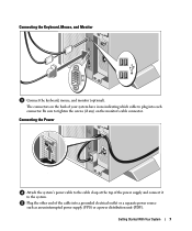
...indicating which cable to the system. Plug the other end of the power supply and connect it to plug into a grounded electrical outlet or a separate power source such as an uninterrupted power supply (UPS) or a power distribution unit (PDU). The connectors on the monitor's cable connector. ...Connecting the Power Attach the system's power cable to the cable clasp at the top of the cable...
...indicating which cable to the system. Plug the other end of the power supply and connect it to plug into a grounded electrical outlet or a separate power source such as an uninterrupted power supply (UPS) or a power distribution unit (PDU). The connectors on the monitor's cable connector. ...Connecting the Power Attach the system's power cable to the cable clasp at the top of the cable...
Getting Started Guide
Page 10
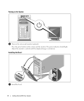
Adjust the monitor's controls until the displayed image is satisfactory. Installing the Bezel Install the bezel. 8 Getting Started With Your System The power indicators should light. Press the power button on the system and monitor (optional). Turning on the System Turn on the system and the monitor.
Adjust the monitor's controls until the displayed image is satisfactory. Installing the Bezel Install the bezel. 8 Getting Started With Your System The power indicators should light. Press the power button on the system and monitor (optional). Turning on the System Turn on the system and the monitor.
Getting Started Guide
Page 12
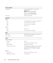
... With Your System Drives (continued) Optical drive Flash drive Connectors Back NIC Serial USB Video Front Video USB Video Video type Video memory Power AC power supply Wattage Voltage Heat dissipation Maximum inrush current Batteries System battery RAID battery (optional) one optional CD, DVD, or combination CD-RW/...-63 Hz 2320 BTU/hr maximum Under typical line conditions and over the entire system ambient operating range, the inrush current may reach 55 A per power supply for integrated 1-GB NIC) 9-pin, DTE, 16550-compatible Four 4-pin, USB 2.0-compliant 15-pin VGA 15-pin VGA Two 4-pin, USB...
... With Your System Drives (continued) Optical drive Flash drive Connectors Back NIC Serial USB Video Front Video USB Video Video type Video memory Power AC power supply Wattage Voltage Heat dissipation Maximum inrush current Batteries System battery RAID battery (optional) one optional CD, DVD, or combination CD-RW/...-63 Hz 2320 BTU/hr maximum Under typical line conditions and over the entire system ambient operating range, the inrush current may reach 55 A per power supply for integrated 1-GB NIC) 9-pin, DTE, 16550-compatible Four 4-pin, USB 2.0-compliant 15-pin VGA 15-pin VGA Two 4-pin, USB...
Hardware Owner's Manual (PDF)
Page 4
... and Closing the System 46 Removing the Bezel 46 Installing the Bezel 47 Opening the System 48 Closing the System 48 Power Supply 50 Removing the Power Supply 50 Installing the Power Supply 51 Fans 52 Removing and Installing a Fan 53 Removing and Installing the Cooling Shroud Fan 54 Expansion Cards 56 Installing...
... and Closing the System 46 Removing the Bezel 46 Installing the Bezel 47 Opening the System 48 Closing the System 48 Power Supply 50 Removing the Power Supply 50 Installing the Power Supply 51 Fans 52 Removing and Installing a Fan 53 Removing and Installing the Cooling Shroud Fan 54 Expansion Cards 56 Installing...
Hardware Owner's Manual (PDF)
Page 6
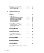
... a Serial I/O Device 105 Troubleshooting a USB Device 105 Troubleshooting a NIC 106 Troubleshooting a Wet System 106 Troubleshooting a Damaged System 107 Troubleshooting the System Battery 108 Troubleshooting the Power Supply 108 Troubleshooting System Cooling Problems 109 Troubleshooting a Fan 109 Troubleshooting System Memory 110 Troubleshooting a Diskette Drive 112 Troubleshooting an Optical Drive 113 Troubleshooting an...
... a Serial I/O Device 105 Troubleshooting a USB Device 105 Troubleshooting a NIC 106 Troubleshooting a Wet System 106 Troubleshooting a Damaged System 107 Troubleshooting the System Battery 108 Troubleshooting the Power Supply 108 Troubleshooting System Cooling Problems 109 Troubleshooting a Fan 109 Troubleshooting System Memory 110 Troubleshooting a Diskette Drive 112 Troubleshooting an Optical Drive 113 Troubleshooting an...

Hardware Owner's Manual (PDF)
Page 12
... to identify a particular system. The identification buttons on the front and back of the system can cause the LCD to flash blue to AC power and an error has been detected, the LCD lights amber regardless of a paper clip. Provides system ID, status information, and system error messages... personnel or by descriptive text. If the system is not running an ACPI-compliant operating system, the system performs a graceful shutdown before the power is on the back blink until one of the buttons is pushed again. Table 1-2. The LCD lights amber when the system needs attention, ...
... to identify a particular system. The identification buttons on the front and back of the system can cause the LCD to flash blue to AC power and an error has been detected, the LCD lights amber regardless of a paper clip. Provides system ID, status information, and system error messages... personnel or by descriptive text. If the system is not running an ACPI-compliant operating system, the system performs a graceful shutdown before the power is on the back blink until one of the buttons is pushed again. Table 1-2. The LCD lights amber when the system needs attention, ...
Hardware Owner's Manual (PDF)
Page 14
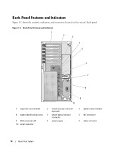
Back-Panel Features and Indicators Figure 1-2 shows the controls, indicators, and connectors located on the system's back panel. Figure 1-2. Back-Panel Features and Indicators 1 2 3 4 5 6 7 8 1 expansion-card slots (6) 4 system identification button 7 USB connectors (4) 10 serial connector 10 2 remote access connector (optional) 5 system status indicator connector 8 power supply 9 3 system status indicator 6 NIC connector 9 video connector 14 About Your System
Back-Panel Features and Indicators Figure 1-2 shows the controls, indicators, and connectors located on the system's back panel. Figure 1-2. Back-Panel Features and Indicators 1 2 3 4 5 6 7 8 1 expansion-card slots (6) 4 system identification button 7 USB connectors (4) 10 serial connector 10 2 remote access connector (optional) 5 system status indicator connector 8 power supply 9 3 system status indicator 6 NIC connector 9 video connector 14 About Your System
Hardware Owner's Manual (PDF)
Page 16
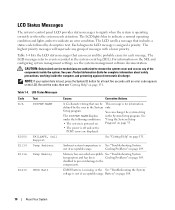
... of the components inside the computer, and protecting against electrostatic discharge. CAUTION: Only trained service technicians are displayed. Program" on page 33. • The power is powered on. Ambient system temperature is operating correctly or when the system needs attention. LCD Status Messages Code Text N/A SYSTEM NAME E1000 E1114 FAILSAFE, Call Support...
... of the components inside the computer, and protecting against electrostatic discharge. CAUTION: Only trained service technicians are displayed. Program" on page 33. • The power is powered on. Ambient system temperature is operating correctly or when the system needs attention. LCD Status Messages Code Text N/A SYSTEM NAME E1000 E1114 FAILSAFE, Call Support...
Hardware Owner's Manual (PDF)
Page 17
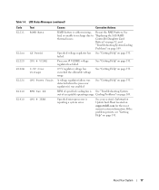
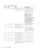
...LCD Status Messages (continued) Code E1211 E12nn E1229 E122B E122C E1310 E1410 Text ROMB Batt XX PwrGd CPU # VCORE 0.9V Over Voltage CPU Power Fault RPM Fan ## CPU # IERR Causes Corrective Actions RAID battery is reporting a system error. Processor # VCORE voltage regulator has failed. ...Table 1-4. See your system's Information Update Tech Sheet located on page 131. Specified voltage regulator has See "Getting Help" on support.dell.com for the most current system information. A voltage regulator failure was detected when the processor regulator(s) was enabled See "Getting Help" on...
...LCD Status Messages (continued) Code E1211 E12nn E1229 E122B E122C E1310 E1410 Text ROMB Batt XX PwrGd CPU # VCORE 0.9V Over Voltage CPU Power Fault RPM Fan ## CPU # IERR Causes Corrective Actions RAID battery is reporting a system error. Processor # VCORE voltage regulator has failed. ...Table 1-4. See your system's Information Update Tech Sheet located on page 131. Specified voltage regulator has See "Getting Help" on support.dell.com for the most current system information. A voltage regulator failure was detected when the processor regulator(s) was enabled See "Getting Help" on...
Hardware Owner's Manual (PDF)
Page 18
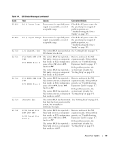
...Getting Help" on page 118. The system BIOS has reported a See "Getting Help" on page 108. Power supply voltage is in a configuration unsupported by Dell. specified power Supply" on page 131. LCD Status Messages (continued) Code E1414 E1418 E141C E141F E1420 E1421 E1422 E1618 Text...LCD continues to display this message until the system's power cord is out of See "Troubleshooting the Power acceptable range; If the problem persists, ensure that your system's Getting Started Guide. See the Dell OpenManage Baseboard Management Controller User's Guide for information about...
...Getting Help" on page 118. The system BIOS has reported a See "Getting Help" on page 108. Power supply voltage is in a configuration unsupported by Dell. specified power Supply" on page 131. LCD Status Messages (continued) Code E1414 E1418 E141C E141F E1420 E1421 E1422 E1618 Text...LCD continues to display this message until the system's power cord is out of See "Troubleshooting the Power acceptable range; If the problem persists, ensure that your system's Getting Started Guide. See the Dell OpenManage Baseboard Management Controller User's Guide for information about...
Hardware Owner's Manual (PDF)
Page 19
... BIOS has reported a system board is faulty. If the problem persists, the system board is faulty. If problem persists, see "Troubleshooting the Power Supply" on page 131. See PCI system error on a component "Getting Help" on page 131. See "Getting Help" on page 131.... in the system, but is faulty. Table 1-4. If problem persists, see "Troubleshooting Expansion Cards" on a component expansion cards. Check the AC power source for the specified power supply. I /O channel check error. PCI PERR B## D## F## PCI PERR Slot # The system BIOS has reported a PCI parity error on ...
... BIOS has reported a system board is faulty. If the problem persists, the system board is faulty. If problem persists, see "Troubleshooting the Power Supply" on page 131. See PCI system error on a component "Getting Help" on page 131. See "Getting Help" on page 131.... in the system, but is faulty. Table 1-4. If problem persists, see "Troubleshooting Expansion Cards" on a component expansion cards. Check the AC power source for the specified power supply. I /O channel check error. PCI PERR B## D## F## PCI PERR Slot # The system BIOS has reported a PCI parity error on ...
Hardware Owner's Manual (PDF)
Page 22
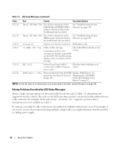
... receive a series of three error events. See "Troubleshooting System Memory" on page 155. See battery has less than 24 hours of events, and is a failing power supply. 22 About Your System NOTE: For the full name of the connections in this table, see the "Glossary" on page 110. LCD Status Messages...
... receive a series of three error events. See "Troubleshooting System Memory" on page 155. See battery has less than 24 hours of events, and is a failing power supply. 22 About Your System NOTE: For the full name of the connections in this table, see the "Glossary" on page 110. LCD Status Messages...
Hardware Owner's Manual (PDF)
Page 23
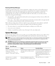
... authorized to notify you receive a system message that can occur and the probable cause and corrective action for the system. • Power cycle - If the problem persists, see "Troubleshooting System Memory" on page 80. About Your System 23 NOTE: If you of range...module(s). For example, if temperature for complete information about safety precautions, working inside the system. wait approximately ten seconds, reconnect the power cable, and restart the system. Causes Corrective Actions Installed memory modules are not the Ensure that is complete. Turn off the ...
... authorized to notify you receive a system message that can occur and the probable cause and corrective action for the system. • Power cycle - If the problem persists, see "Troubleshooting System Memory" on page 80. About Your System 23 NOTE: If you of range...module(s). For example, if temperature for complete information about safety precautions, working inside the system. wait approximately ten seconds, reconnect the power cable, and restart the system. Causes Corrective Actions Installed memory modules are not the Ensure that is complete. Turn off the ...
Hardware Owner's Manual (PDF)
Page 25
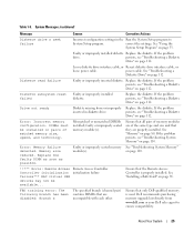
...diskette. Diskette subsystem reset failed Faulty or improperly installed diskette. Replace the diskette. Memory size reduced. About Your System 25 power cable. Replace the diskette. If the problem persists, see "Troubleshooting System Memory" on page 112. DIMMs must be available... on page 112. Dell recommends purchasing memory upgrade kits directly from or improperly inserted in the Run the System Setup program to ensure compatibility. Loose diskette drive interface cable, or Reseat diskette drive interface cable, or loose power cable. on page ...
...diskette. Diskette subsystem reset failed Faulty or improperly installed diskette. Replace the diskette. Memory size reduced. About Your System 25 power cable. Replace the diskette. If the problem persists, see "Troubleshooting System Memory" on page 112. DIMMs must be available... on page 112. Dell recommends purchasing memory upgrade kits directly from or improperly inserted in the Run the System Setup program to ensure compatibility. Loose diskette drive interface cable, or Reseat diskette drive interface cable, or loose power cable. on page ...

Hardware Owner's Manual (PDF)
Page 31
About Your System 31 Alert Messages Systems management software generates alert messages for drive, temperature, fan, and power conditions. For more information, see the systems management software documentation. Alert messages include information, status, warning, and failure messages for your system.
About Your System 31 Alert Messages Systems management software generates alert messages for drive, temperature, fan, and power conditions. For more information, see the systems management software documentation. Alert messages include information, status, warning, and failure messages for your system.
Hardware Owner's Manual (PDF)
Page 37
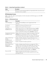
... Enabled permits all logical processors to be reported to use of random memory access. Demand-Based Power Management (Disabled default) Enables or disables demand-based power management. Adjacent Cache Line Prefetch (Enabled default) Enables or disables optimal use Virtualization Technology incorporated ... default) Displays when the processors support HyperThreading. Only the first logical processor of the CPUs do not support demand-based power management, the field will not be used by software that require high use of sequential memory access. If any of ...
... Enabled permits all logical processors to be reported to use of random memory access. Demand-Based Power Management (Disabled default) Enables or disables demand-based power management. Adjacent Cache Line Prefetch (Enabled default) Enables or disables optimal use Virtualization Technology incorporated ... default) Displays when the processors support HyperThreading. Only the first logical processor of the CPUs do not support demand-based power management, the field will not be used by software that require high use of sequential memory access. If any of ...
Hardware Owner's Manual (PDF)
Page 40
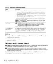
... Use the NMI button only if directed to do so by qualified support personnel or by changing a jumper setting. When set to the last power state. If system security is enabled in the System Setup program. The button is a concern, operate your system unlocked so that someone can perform... an orderly shutdown before power is turned off. • If the system is not running and unattended without the system password feature enabled. When disabled, the button can ...
... Use the NMI button only if directed to do so by qualified support personnel or by changing a jumper setting. When set to the last power state. If system security is enabled in the System Setup program. The button is a concern, operate your system unlocked so that someone can perform... an orderly shutdown before power is turned off. • If the system is not running and unattended without the system password feature enabled. When disabled, the button can ...
Hardware Owner's Manual (PDF)
Page 44
... logging and SNMP alerting • Access to system event log and sensor status • Control of system functions including power on or restart your operating system begins to load before you want to clear the existing setup password. Baseboard Management Controller... Configuration The Baseboard Management Controller (BMC) enables configuring, monitoring, and recovery of the system's power or operating state • Provides text console redirection for the BMC and systems management applications. BMC Setup Module Options For information...
... logging and SNMP alerting • Access to system event log and sensor status • Control of system functions including power on or restart your operating system begins to load before you want to clear the existing setup password. Baseboard Management Controller... Configuration The Baseboard Management Controller (BMC) enables configuring, monitoring, and recovery of the system's power or operating state • Provides text console redirection for the BMC and systems management applications. BMC Setup Module Options For information...
Hardware Owner's Manual (PDF)
Page 45
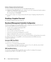
Installing System Components This section describes how to install the following system components: • Power supply • Cooling fans • Expansion cards • Hard drives • Tape, optical, and diskette drives • System battery • System memory • RAC card &#...
Installing System Components This section describes how to install the following system components: • Power supply • Cooling fans • Expansion cards • Hard drives • Tape, optical, and diskette drives • System battery • System memory • RAC card &#...


