

Getting Started Guide
Page 5
... Features The major hardware and software features of your system by installing a second processor, you must order the processor upgrade kits from Dell contains the correct version of the processor and heat sink. • A minimum of 512 MB of 533 or 667 MHz (when... 3.3-V, 64-bit, 133-MHz PCI-X slots; Slot 1 accommodates halflength expansion cards. The upgrade kit from Dell. slot 3 is opened. • An 800-W power supply. • Six system cooling fans. Getting Started With Your System 3 SMP greatly improves overall system performance by installing combinations of 256-MB, 512...
... Features The major hardware and software features of your system by installing a second processor, you must order the processor upgrade kits from Dell contains the correct version of the processor and heat sink. • A minimum of 512 MB of 533 or 667 MHz (when... 3.3-V, 64-bit, 133-MHz PCI-X slots; Slot 1 accommodates halflength expansion cards. The upgrade kit from Dell. slot 3 is opened. • An 800-W power supply. • Six system cooling fans. Getting Started With Your System 3 SMP greatly improves overall system performance by installing combinations of 256-MB, 512...
Getting Started Guide
Page 6
... is 1024 X 768. • Systems management circuitry that monitors operation of DDR SDRAM video memory (nonupgradable). This video subsystem contains 16 MB of the system fans as well as critical system voltages and temperatures. Supported Operating Systems • Microsoft® Windows Server™ 2003 Standard and Enterprise Editions • Microsoft Windows...
... is 1024 X 768. • Systems management circuitry that monitors operation of DDR SDRAM video memory (nonupgradable). This video subsystem contains 16 MB of the system fans as well as critical system voltages and temperatures. Supported Operating Systems • Microsoft® Windows Server™ 2003 Standard and Enterprise Editions • Microsoft Windows...
Hardware Owner's Manual (PDF)
Page 4
... the System 48 Closing the System 48 Power Supply 50 Removing the Power Supply 50 Installing the Power Supply 51 Fans 52 Removing and Installing a Fan 53 Removing and Installing the Cooling Shroud Fan 54 Expansion Cards 56 Installing an Expansion Card 57 Removing an Expansion Card 58 Hard Drives 59 Removing a Hard...
... the System 48 Closing the System 48 Power Supply 50 Removing the Power Supply 50 Installing the Power Supply 51 Fans 52 Removing and Installing a Fan 53 Removing and Installing the Cooling Shroud Fan 54 Expansion Cards 56 Installing an Expansion Card 57 Removing an Expansion Card 58 Hard Drives 59 Removing a Hard...

Hardware Owner's Manual (PDF)
Page 5
... Battery 75 Cooling Shroud 77 Removing the Cooling Shroud 77 Installing the Cooling Shroud 79 Fan Brackets 79 Removing the Center Fan Bracket 79 Replacing the Center Fan Bracket 79 Removing the Back Fan Bracket 80 Replacing the Back Fan Bracket 80 Memory 80 General Memory Module Installation Guidelines 82 Non-Optimal Memory Configurations 82...
... Battery 75 Cooling Shroud 77 Removing the Cooling Shroud 77 Installing the Cooling Shroud 79 Fan Brackets 79 Removing the Center Fan Bracket 79 Replacing the Center Fan Bracket 79 Removing the Back Fan Bracket 80 Replacing the Back Fan Bracket 80 Memory 80 General Memory Module Installation Guidelines 82 Non-Optimal Memory Configurations 82...
Hardware Owner's Manual (PDF)
Page 6
... 106 Troubleshooting a Wet System 106 Troubleshooting a Damaged System 107 Troubleshooting the System Battery 108 Troubleshooting the Power Supply 108 Troubleshooting System Cooling Problems 109 Troubleshooting a Fan 109 Troubleshooting System Memory 110 Troubleshooting a Diskette Drive 112 Troubleshooting an Optical Drive 113 Troubleshooting an External SCSI Tape Drive 113 Troubleshooting a Hard Drive 115...
... 106 Troubleshooting a Wet System 106 Troubleshooting a Damaged System 107 Troubleshooting the System Battery 108 Troubleshooting the Power Supply 108 Troubleshooting System Cooling Problems 109 Troubleshooting a Fan 109 Troubleshooting System Memory 110 Troubleshooting a Diskette Drive 112 Troubleshooting an Optical Drive 113 Troubleshooting an External SCSI Tape Drive 113 Troubleshooting a Hard Drive 115...
Hardware Owner's Manual (PDF)
Page 17
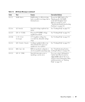
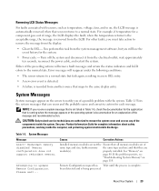
Specified microprocessor is See "Troubleshooting System out of specified cooling fan is reporting a system error. If the problem persists, see "Getting Help" on support.dell.com for the most current system information. failed. About Your System 17 See your system's Information Update Tech Sheet... (continued) Code E1211 E12nn E1229 E122B E122C E1310 E1410 Text ROMB Batt XX PwrGd CPU # VCORE 0.9V Over Voltage CPU Power Fault RPM Fan ## CPU # IERR Causes Corrective Actions RAID battery is either missing, Reseat the RAID battery. See "Getting Help" on page 131. 0.9...
Specified microprocessor is See "Troubleshooting System out of specified cooling fan is reporting a system error. If the problem persists, see "Getting Help" on support.dell.com for the most current system information. failed. About Your System 17 See your system's Information Update Tech Sheet... (continued) Code E1211 E12nn E1229 E122B E122C E1310 E1410 Text ROMB Batt XX PwrGd CPU # VCORE 0.9V Over Voltage CPU Power Fault RPM Fan ## CPU # IERR Causes Corrective Actions RAID battery is either missing, Reseat the RAID battery. See "Getting Help" on page 131. 0.9...
Hardware Owner's Manual (PDF)
Page 23
... LCD displays the fault; You perform this task from another source that all memory modules are of a possible problem with sensors, such as temperature, voltage, fans, and so on the screen to notify you must take action to remove the system cover and access any of the message and recommended action...
... LCD displays the fault; You perform this task from another source that all memory modules are of a possible problem with sensors, such as temperature, voltage, fans, and so on the screen to notify you must take action to remove the system cover and access any of the message and recommended action...

Hardware Owner's Manual (PDF)
Page 31
For more information, see the systems management software documentation. About Your System 31 Alert Messages Systems management software generates alert messages for drive, temperature, fan, and power conditions. Alert messages include information, status, warning, and failure messages for your system.
For more information, see the systems management software documentation. About Your System 31 Alert Messages Systems management software generates alert messages for drive, temperature, fan, and power conditions. Alert messages include information, status, warning, and failure messages for your system.
Hardware Owner's Manual (PDF)
Page 45
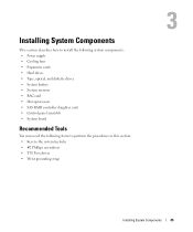
Installing System Components This section describes how to install the following system components: • Power supply • Cooling fans • Expansion cards • Hard drives • Tape, optical, and diskette drives • System battery • System memory • RAC card • Microprocessors • SAS ...
Installing System Components This section describes how to install the following system components: • Power supply • Cooling fans • Expansion cards • Hard drives • Tape, optical, and diskette drives • System battery • System memory • RAC card • Microprocessors • SAS ...
Hardware Owner's Manual (PDF)
Page 50
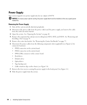
... drive • Tape backup unit • Cable retention clips on page 48. 4 Remove the expansion-bay and processor-cooling fans (FAN1, FAN2, and FAN3). See "Removing the Center Fan Bracket" on page 79. 6 Disconnect the power cables from the following components where applicable (see Figure 3-4) 7 Remove the .... NOTICE: To ensure proper system cooling, the power supply blank must be installed on page 53. 5 Remove the center fan bracket. See "Removing and Installing a Fan" on the unoccupied power supply bay. Power Supply Your system supports one power supply rated at an output of 800 W.
... drive • Tape backup unit • Cable retention clips on page 48. 4 Remove the expansion-bay and processor-cooling fans (FAN1, FAN2, and FAN3). See "Removing the Center Fan Bracket" on page 79. 6 Disconnect the power cables from the following components where applicable (see Figure 3-4) 7 Remove the .... NOTICE: To ensure proper system cooling, the power supply blank must be installed on page 53. 5 Remove the center fan bracket. See "Removing and Installing a Fan" on the unoccupied power supply bay. Power Supply Your system supports one power supply rated at an output of 800 W.
Hardware Owner's Manual (PDF)
Page 52
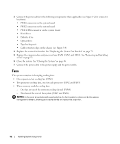
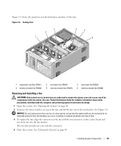
... rear of the system (FAN5 and FAN6) NOTICE: In the event of the memory cooling shroud (FAN4) - One fan on top of a problem with a particular fan, the fan's number is referenced by the systems management software, allowing you to the power supply and the power outlet. See "Closing... the System" on page 53. 6 Close the system. Fans The system contains six hot-plug cooling fans: • One expansion-bay cooling fan (FAN1) • Two processor cooling fans, one for connector locations): • PWR1 connector on the system board • PWR2 connector...
... rear of the system (FAN5 and FAN6) NOTICE: In the event of the memory cooling shroud (FAN4) - One fan on top of a problem with a particular fan, the fan's number is referenced by the systems management software, allowing you to the power supply and the power outlet. See "Closing... the System" on page 53. 6 Close the system. Fans The system contains six hot-plug cooling fans: • One expansion-bay cooling fan (FAN1) • Two processor cooling fans, one for connector locations): • PWR1 connector on the system board • PWR2 connector...
Hardware Owner's Manual (PDF)
Page 53
... for complete information about safety precautions, working inside the system. NOTICE: Do not remove more than one fan at a time and do not operate the system with the fan connector on page 48. Overheating can occur, resulting in a system shutdown and loss of time. Figure 3-5. ...See your Product Information Guide for an extended period of data. 3 To replace the fan, align the connector on the fan with any of the components inside the computer, and protecting against electrostatic discharge. 1 Open the system. See Figure 3-6. See "Closing...
... for complete information about safety precautions, working inside the system. NOTICE: Do not remove more than one fan at a time and do not operate the system with the fan connector on page 48. Overheating can occur, resulting in a system shutdown and loss of time. Figure 3-5. ...See your Product Information Guide for an extended period of data. 3 To replace the fan, align the connector on the fan with any of the components inside the computer, and protecting against electrostatic discharge. 1 Open the system. See Figure 3-6. See "Closing...
Hardware Owner's Manual (PDF)
Page 54
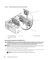
... inside the computer, and protecting against electrostatic discharge. See Figure 3-7. Installing and Removing a Fan From the Fan Brackets 1 2 3 4 1 fan release latches (2) 4 fan connector on each side of the fan bracket, and then rotate the bracket to the up position. See "Opening the System" on... remove the cooling shroud from the cooling shroud by squeezing the latches on system board 2 fan 3 center fan bracket Removing and Installing the Cooling Shroud Fan CAUTION: Only trained service technicians are authorized to perform this step. 54 Installing System Components
... inside the computer, and protecting against electrostatic discharge. See Figure 3-7. Installing and Removing a Fan From the Fan Brackets 1 2 3 4 1 fan release latches (2) 4 fan connector on each side of the fan bracket, and then rotate the bracket to the up position. See "Opening the System" on... remove the cooling shroud from the cooling shroud by squeezing the latches on system board 2 fan 3 center fan bracket Removing and Installing the Cooling Shroud Fan CAUTION: Only trained service technicians are authorized to perform this step. 54 Installing System Components
Hardware Owner's Manual (PDF)
Page 55
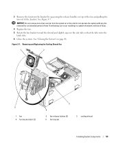
See Figure 3-7. Figure 3-7. Removing and Replacing the Cooling Shroud Fan 1 2 5 1 fan 4 fan bracket latch (2) 3 4 2 fan release latches (2) 5 fan bracket 3 cooling shroud Installing System Components 55 NOTICE: Do not remove more than one fan from the bracket by squeezing the release handles on page 48. Overheating can occur resulting...shutdown and loss of time. 3 Remove the fan from the system at a time and do not operate the system with any fan removed for an extended period of data. 4 Replace the fan. 5 Rotate the fan bracket toward the shroud and slightly squeeze the side...
See Figure 3-7. Figure 3-7. Removing and Replacing the Cooling Shroud Fan 1 2 5 1 fan 4 fan bracket latch (2) 3 4 2 fan release latches (2) 5 fan bracket 3 cooling shroud Installing System Components 55 NOTICE: Do not remove more than one fan from the bracket by squeezing the release handles on page 48. Overheating can occur resulting...shutdown and loss of time. 3 Remove the fan from the system at a time and do not operate the system with any fan removed for an extended period of data. 4 Replace the fan. 5 Rotate the fan bracket toward the shroud and slightly squeeze the side...
Hardware Owner's Manual (PDF)
Page 59
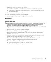
... page 48. 11 Connect the power cable to the system. See "Removing the Center Fan Bracket" on page 48. 4 Remove the expansion-bay and processor fans (FAN1, FAN2, and FAN3). Hard Drives Removing a Hard Drive CAUTION: Only trained service technicians are authorized to ...See "Removing the Bezel" on the stabilizer into place against electrostatic discharge. 1 Turn off the system, including any of the center fans. 6 Remove the center fan bracket. See Figure 3-10. See your Product Information Guide for complete information about safety precautions, working inside the system. 8 If ...
... page 48. 11 Connect the power cable to the system. See "Removing the Center Fan Bracket" on page 48. 4 Remove the expansion-bay and processor fans (FAN1, FAN2, and FAN3). Hard Drives Removing a Hard Drive CAUTION: Only trained service technicians are authorized to ...See "Removing the Bezel" on the stabilizer into place against electrostatic discharge. 1 Turn off the system, including any of the center fans. 6 Remove the center fan bracket. See Figure 3-10. See your Product Information Guide for complete information about safety precautions, working inside the system. 8 If ...
Hardware Owner's Manual (PDF)
Page 62
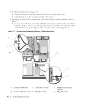
... interface and power cables as follows: • For up to two SATA drives, connect the cables to the two SATA connectors on System Board) 6 5 4 1 2 3 1 center fan retention cage 2 power cable connector 4 hard drive interface connector 5 SATA_A connector 62 Installing System Components 3 hard drive interface cable connector 6 SATA_B connector Route the cables...
... interface and power cables as follows: • For up to two SATA drives, connect the cables to the two SATA connectors on System Board) 6 5 4 1 2 3 1 center fan retention cage 2 power cable connector 4 hard drive interface connector 5 SATA_A connector 62 Installing System Components 3 hard drive interface cable connector 6 SATA_B connector Route the cables...
Hardware Owner's Manual (PDF)
Page 63
... slot 4 (PCIE_X4_4). • For up to the connector on the system board and the connector on the card itself. Route the cables through the center fan retention cage.
... slot 4 (PCIE_X4_4). • For up to the connector on the system board and the connector on the card itself. Route the cables through the center fan retention cage.
Hardware Owner's Manual (PDF)
Page 64
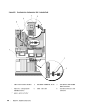
Four-hard-drive Configuration (SAS Controller Card) 3 2 4 5 1 6 7 1 central fan retention bracket 2 expansion-slot 4 (PCIE_X4_4) 3 hard drive activity system board connector 4 hard drive activity system board connector 5 SAS1 connector 6 hard drive interface cable connector 7 power cable connector 64 Installing System Components Figure 3-13.
Four-hard-drive Configuration (SAS Controller Card) 3 2 4 5 1 6 7 1 central fan retention bracket 2 expansion-slot 4 (PCIE_X4_4) 3 hard drive activity system board connector 4 hard drive activity system board connector 5 SAS1 connector 6 hard drive interface cable connector 7 power cable connector 64 Installing System Components Figure 3-13.
Hardware Owner's Manual (PDF)
Page 65
... SAS or SATA drives in a RAID configuration and illustrated in Figure 3-13 should only be installed into slot 4 (PCIE_X4_4). Route the cables through the center fan retention cage. • For up to an optional SAS RAID controller daughter card installed into the integrated daughter card slot (INT_STORAGE). Installing System Components 65...
... SAS or SATA drives in a RAID configuration and illustrated in Figure 3-13 should only be installed into slot 4 (PCIE_X4_4). Route the cables through the center fan retention cage. • For up to an optional SAS RAID controller daughter card installed into the integrated daughter card slot (INT_STORAGE). Installing System Components 65...
Hardware Owner's Manual (PDF)
Page 66
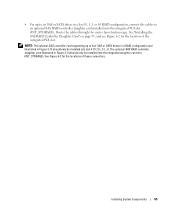
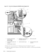
... activity system board connector (HD_ACT_CARD) 2 SAS RAID controller daughter 3 SASx connector (2) card battery connector 4 hard drive LED activity cable 5 center fan retention cage connector 6 hard drive interface cable connector 7 hard drive power connector 5 Replace the center fan bracket. Figure 3-14. See "Replacing the Center Fan Bracket" on page 53. 66 Installing System Components
... activity system board connector (HD_ACT_CARD) 2 SAS RAID controller daughter 3 SASx connector (2) card battery connector 4 hard drive LED activity cable 5 center fan retention cage connector 6 hard drive interface cable connector 7 hard drive power connector 5 Replace the center fan bracket. Figure 3-14. See "Replacing the Center Fan Bracket" on page 53. 66 Installing System Components


