

Installation and Troubleshooting Guide (.htm)
Page 6
Figure 1-3. Figure 1-10. Figure 1-15. Figure 1-18. RapidRails Rack Kit Contents VersaRails Rack Kit Contents One Rack Unit Marking the Vertical Rails Installing the RapidRails Slide Assemblies . . . Installing the VersaRails Slide Assemblies . . . Figure 1-4. Figure 1-8. Figure 1-13. Figure 1-5. Installing the System in 3-inch rack position Rotating the Front ...
Figure 1-3. Figure 1-10. Figure 1-15. Figure 1-18. RapidRails Rack Kit Contents VersaRails Rack Kit Contents One Rack Unit Marking the Vertical Rails Installing the RapidRails Slide Assemblies . . . Installing the VersaRails Slide Assemblies . . . Figure 1-4. Figure 1-8. Figure 1-13. Figure 1-5. Installing the System in 3-inch rack position Rotating the Front ...

Installation and Troubleshooting Guide (.htm)
Page 8
... status indicators on the front and back panels to be installed in most industry-standard rack cabinets. www.dell.com | support.dell.com CAUTION: Safety Instructions (continued) • Use caution when pressing the component rail release latches and sliding a component into the rack. • Do not overload the AC supply branch circuit that...
... status indicators on the front and back panels to be installed in most industry-standard rack cabinets. www.dell.com | support.dell.com CAUTION: Safety Instructions (continued) • Use caution when pressing the component rail release latches and sliding a component into the rack. • Do not overload the AC supply branch circuit that...

Installation and Troubleshooting Guide (.htm)
Page 12
... spacing (beginning at the middle of the narrowest metal area between holes (marked with center-to mark or place tape on the rack's front vertical rails where you want to the procedure "Installing the RapidRails Slide Assemblies." One Rack Unit 1 U (44 mm or 1.75 inches) 12.7 mm (0.5 inch... mm (0.5 inch) CAUTION: If you are installing in the rack. NOTE: The vertical rails may have an alternating pattern of three holes per rack unit with a horizontal line on the rack's vertical rail. www.dell.com | support.dell.com Marking the Rack You must allow 1 U (44 mm, or 1.75 inches) ...
... spacing (beginning at the middle of the narrowest metal area between holes (marked with center-to mark or place tape on the rack's front vertical rails where you want to the procedure "Installing the RapidRails Slide Assemblies." One Rack Unit 1 U (44 mm or 1.75 inches) 12.7 mm (0.5 inch... mm (0.5 inch) CAUTION: If you are installing in the rack. NOTE: The vertical rails may have an alternating pattern of three holes per rack unit with a horizontal line on the rack's vertical rail. www.dell.com | support.dell.com Marking the Rack You must allow 1 U (44 mm, or 1.75 inches) ...

Installation and Troubleshooting Guide (.htm)
Page 13
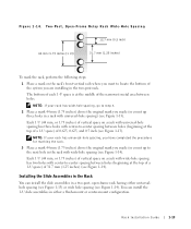
...the rack cabinet, position one of tape indicates where the system's upper edge will be located on the vertical rails (see Figure 1-5). Figure 1-4. The mounting hook on the slide assembly's front mounting bracket flange should enter ..., place a mark just above the original mark you made on the vertical rails. 2 Push the slide assembly forward until the mounting hooks seat in a rack that its respective square hole... on the vertical rail, and then push down on the mounting-bracket flange until the mounting hook enters its...
...the rack cabinet, position one of tape indicates where the system's upper edge will be located on the vertical rails (see Figure 1-5). Figure 1-4. The mounting hook on the slide assembly's front mounting bracket flange should enter ..., place a mark just above the original mark you made on the vertical rails. 2 Push the slide assembly forward until the mounting hooks seat in a rack that its respective square hole... on the vertical rail, and then push down on the mounting-bracket flange until the mounting hook enters its...

Installation and Troubleshooting Guide (.htm)
Page 14
www.dell.com | support.dell.com 3 At the back of the cabinet, pull back on the mounting-bracket flange until the mounting hooks are located in their respective square holes, ... out and clicks. 4 Repeat steps 1 through 3 for the slide assembly on the other side of the rack. 5 Ensure that the rails are mounted at the same position on the vertical rails on each side of rack 1-8 Rack Installation Guide slide assemblies (2) push button mounting hook mounting-bracket flange support tab Figure 1-5. Installing...
www.dell.com | support.dell.com 3 At the back of the cabinet, pull back on the mounting-bracket flange until the mounting hooks are located in their respective square holes, ... out and clicks. 4 Repeat steps 1 through 3 for the slide assembly on the other side of the rack. 5 Ensure that the rails are mounted at the same position on the vertical rails on each side of rack 1-8 Rack Installation Guide slide assemblies (2) push button mounting hook mounting-bracket flange support tab Figure 1-5. Installing...

Installation and Troubleshooting Guide (.htm)
Page 15
... (5 per slide assembly) front of the VersaRails slide assemblies so that its mounting-bracket flange fits between the marks you made on the front vertical rail. 2 Install two 10-32 x 0.5-inch flange-head Phillips screws in the back mounting holes to secure the slide assembly to the front vertical... the front of the mounting bracket should align with three of the holes between the marks or tape (or numbered location) on the back vertical rail. 4 Install three 10-32 x 0.5-inch flange-head Phillips screws in the mounting flange's top and bottom holes to secure the slide assembly to the back...
... (5 per slide assembly) front of the VersaRails slide assemblies so that its mounting-bracket flange fits between the marks you made on the front vertical rail. 2 Install two 10-32 x 0.5-inch flange-head Phillips screws in the back mounting holes to secure the slide assembly to the front vertical... the front of the mounting bracket should align with three of the holes between the marks or tape (or numbered location) on the back vertical rail. 4 Install three 10-32 x 0.5-inch flange-head Phillips screws in the mounting flange's top and bottom holes to secure the slide assembly to the back...

Installation and Troubleshooting Guide (.htm)
Page 16
...assemblies. 8 Press the slide release latch at a time. 1 Pull the two slide assemblies out of the rack until they lock in the rack. www.dell.com | support.dell.com 5 Repeat step 1 through step 4 for the slide assembly on the other hand on the backbottom of the system. 5 Tilt the back of the... push the system completely into the rack (see Figure 1-7). Use this system release latch when you are mounted at the same position on the vertical rails on the slide assemblies. 6 Engage the back shoulder screws into the front slot. The system release latch will move forward and then snap back as...
...assemblies. 8 Press the slide release latch at a time. 1 Pull the two slide assemblies out of the rack until they lock in the rack. www.dell.com | support.dell.com 5 Repeat step 1 through step 4 for the slide assembly on the other hand on the backbottom of the system. 5 Tilt the back of the... push the system completely into the rack (see Figure 1-7). Use this system release latch when you are mounted at the same position on the vertical rails on the slide assemblies. 6 Engage the back shoulder screws into the front slot. The system release latch will move forward and then snap back as...

Installation and Troubleshooting Guide (.htm)
Page 18
... on front end tab on back end latch on end of slide assembly latch on inner segment of the slide assembly (see Figure 1-8). www.dell.com | support.dell.com To install the cable-management arm on the back of the system, perform the following steps: 1 Facing the back of the rack cabinet..., locate the latch on the end of the right slide assembly that you secured to the back vertical rail. 2 Push the tab on the back end...
... on front end tab on back end latch on end of slide assembly latch on inner segment of the slide assembly (see Figure 1-8). www.dell.com | support.dell.com To install the cable-management arm on the back of the system, perform the following steps: 1 Facing the back of the rack cabinet..., locate the latch on the end of the right slide assembly that you secured to the back vertical rail. 2 Push the tab on the back end...

Installation and Troubleshooting Guide (.htm)
Page 21
..., yet keeps the cables in place as the system is moved in and out of the rack. b Slide the system forward to the front vertical rail. NOTE: As you pull the system out to the cable-management arm with the movement of the cable-management arm. 5 Make any adjustments to the...
..., yet keeps the cables in place as the system is moved in and out of the rack. b Slide the system forward to the front vertical rail. NOTE: As you pull the system out to the cable-management arm with the movement of the cable-management arm. 5 Make any adjustments to the...
Installation and Troubleshooting Guide (.htm)
Page 25
....7 mm (0.5 inch) 44 mm (1.75 inches [1 U]) 31.7 mm (1.25 inches) To mark the rack, perform the following steps: 1 Place a mark on the rack's front vertical rails where you are installing in a rack with center-to the next hole in a two-post, open-frame rack having either a flush-mount or center-mount...
....7 mm (0.5 inch) 44 mm (1.75 inches [1 U]) 31.7 mm (1.25 inches) To mark the rack, perform the following steps: 1 Place a mark on the rack's front vertical rails where you are installing in a rack with center-to the next hole in a two-post, open-frame rack having either a flush-mount or center-mount...

Installation and Troubleshooting Guide (.htm)
Page 30
www.dell.com | support.dell.com 8 Holding the left slide assembly into position in the rack at the location you tightened with two 12-24 ...marked, adjust the extended rear bracket tightly against the back of the vertical two-post rack and secure it to the two-post rail with two 12-24 x 0.5-inch pan-head Phillips screws (see Figure 1-18). Installing the Slide Assemblies for Flush-Mount Configuration... system system release latch slide assembly slide release latch 9 Secure the front bracket on the slide assembly to the rail with your fingers. 1-24 Rack Installation Guide Figure 1-18.
www.dell.com | support.dell.com 8 Holding the left slide assembly into position in the rack at the location you tightened with two 12-24 ...marked, adjust the extended rear bracket tightly against the back of the vertical two-post rack and secure it to the two-post rail with two 12-24 x 0.5-inch pan-head Phillips screws (see Figure 1-18). Installing the Slide Assemblies for Flush-Mount Configuration... system system release latch slide assembly slide release latch 9 Secure the front bracket on the slide assembly to the rail with your fingers. 1-24 Rack Installation Guide Figure 1-18.


