

Rack Installation Guide
Page 3
... Installing the Cable-Management Arm 1-11 Routing Cables 1-14 Replacing the Rack Doors 1-16 Two-Post Rack Installation Recommended Tools and Supplies Rack Kit Contents Two-Post Rack Installation Tasks Marking the Rack Installing the Slide Assemblies in the Rack Installing the System in the Rack Installing the Cable-Management Arm Routing Cables 1-16 1-16 1-17 1-17...
... Installing the Cable-Management Arm 1-11 Routing Cables 1-14 Replacing the Rack Doors 1-16 Two-Post Rack Installation Recommended Tools and Supplies Rack Kit Contents Two-Post Rack Installation Tasks Marking the Rack Installing the Slide Assemblies in the Rack Installing the System in the Rack Installing the Cable-Management Arm Routing Cables 1-16 1-16 1-17 1-17...
Rack Installation Guide
Page 4
... Wire Covers Installing the Power Cord Strain Relief . . . Figure 1-7. Figure 1-13. Figure 1-2. Figure 1-17. Installing the VersaRails Slide Assemblies . . . Figure 1-8. Installing the System in 3-inch rack position Rotating the Front Mounting Bracket for Flush-Mount Installation Installing the Slide Assemblies for Flush-Mount Configuration 1-4 1-5 1-6 1-7 1-8 1-9 1-11 1-12 1-13 1-14 1-15 1-17 1-18...
... Wire Covers Installing the Power Cord Strain Relief . . . Figure 1-7. Figure 1-13. Figure 1-2. Figure 1-17. Installing the VersaRails Slide Assemblies . . . Figure 1-8. Installing the System in 3-inch rack position Rotating the Front Mounting Bracket for Flush-Mount Installation Installing the Slide Assemblies for Flush-Mount Configuration 1-4 1-5 1-6 1-7 1-8 1-9 1-11 1-12 1-13 1-14 1-15 1-17 1-18...

Rack Installation Guide
Page 5
... this task. • Before working on the rack, make sure that the stabilizers are secured to the rack, extended to the floor, and that the full weight of a Dell rack. Therefore, always install the stabilizers before working environment from the rack. NOTE: Your system is your responsibility to ensure... the System Information Guide. The weight of more than one time. Install front and side stabilizers on a single rack or front stabilizers for use in a Dell™ rack cabinet using the customer rack kit. If you install the kit in any system as well as a component for joined multiple...
... this task. • Before working on the rack, make sure that the stabilizers are secured to the rack, extended to the floor, and that the full weight of a Dell rack. Therefore, always install the stabilizers before working environment from the rack. NOTE: Your system is your responsibility to ensure... the System Information Guide. The weight of more than one time. Install front and side stabilizers on a single rack or front stabilizers for use in a Dell™ rack cabinet using the customer rack kit. If you install the kit in any system as well as a component for joined multiple...

Rack Installation Guide
Page 6
... (installed in either center-mount or flush-mount configuration) For ease in the rack cabinet. www.dell.com | support.dell.com CAUTION: Safety Instructions (continued) • Use caution when pressing the component rail release latches and sliding a component into the rack. • Do not overload the AC supply branch circuit that extends the information...
... (installed in either center-mount or flush-mount configuration) For ease in the rack cabinet. www.dell.com | support.dell.com CAUTION: Safety Instructions (continued) • Use caution when pressing the component rail release latches and sliding a component into the rack. • Do not overload the AC supply branch circuit that extends the information...
Rack Installation Guide
Page 7
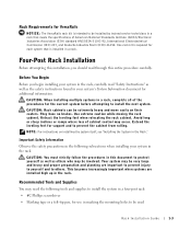
...ANSI/EIA-310-D-92, International Electrotechnical Commission (IEC) 297, and Deutsche Industrie Norm (DIN) 41494. Use extreme caution while moving the rack cabinet. CAUTION: You must strictly follow the procedures in this document to others who may need the following subsections when installing your system...to be involved. Important Safety Information Observe the safety precautions in the following tools and supplies to install the system in a four-post rack: • #2 Phillips screwdriver • Masking tape or a felt-tip pen, for use in marking the mounting holes to be ...
...ANSI/EIA-310-D-92, International Electrotechnical Commission (IEC) 297, and Deutsche Industrie Norm (DIN) 41494. Use extreme caution while moving the rack cabinet. CAUTION: You must strictly follow the procedures in this document to others who may need the following subsections when installing your system...to be involved. Important Safety Information Observe the safety precautions in the following tools and supplies to install the system in a four-post rack: • #2 Phillips screwdriver • Masking tape or a felt-tip pen, for use in marking the mounting holes to be ...
Rack Installation Guide
Page 8
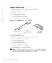
... Contents cable-management arm slide assemblies (2) status-indicator cable stop blocks (2) VersaRails Rack Kit Contents The VersaRails rack kit includes the following items (see Figure 1-2): • One pair of VersaRails slide assemblies • One cable-management arm •...in illustrations and in Figure 1-1) Figure 1-1. For example, a #10 Phillips-head screw with 32 threads per -inch. www.dell.com | support.dell.com RapidRails Rack Kit Contents The RapidRails rack kit includes the following items (see Figure 1-1): • One pair of threads-per inch is identified as a 10-32 ...
... Contents cable-management arm slide assemblies (2) status-indicator cable stop blocks (2) VersaRails Rack Kit Contents The VersaRails rack kit includes the following items (see Figure 1-2): • One pair of VersaRails slide assemblies • One cable-management arm •...in illustrations and in Figure 1-1) Figure 1-1. For example, a #10 Phillips-head screw with 32 threads per -inch. www.dell.com | support.dell.com RapidRails Rack Kit Contents The RapidRails rack kit includes the following items (see Figure 1-1): • One pair of threads-per inch is identified as a 10-32 ...

Rack Installation Guide
Page 9
... (2) stop blocks (2) 10-32 x 0.5-inch flange-head status-indicator cable Phillips screws (10) Installation Tasks Installing a rack kit involves performing the following tasks in their numbered order: 1 Removing the rack doors 2 Marking the rack 3 Installing the slide assemblies in the rack • RapidRails slide assemblies • VersaRails slide assemblies 4 Installing the system in the...
... (2) stop blocks (2) 10-32 x 0.5-inch flange-head status-indicator cable Phillips screws (10) Installation Tasks Installing a rack kit involves performing the following tasks in their numbered order: 1 Removing the rack doors 2 Marking the rack 3 Installing the slide assemblies in the rack • RapidRails slide assemblies • VersaRails slide assemblies 4 Installing the system in the...
Rack Installation Guide
Page 10
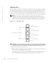
... (beginning at the middle of the narrowest metal area between holes (marked with center-to mark or place tape on the rack's vertical rail. www.dell.com | support.dell.com Marking the Rack You must allow 1 U (44 mm, or 1.75 inches) of vertical space for each 1-U space is at the top hole of a 1-U space...
... (beginning at the middle of the narrowest metal area between holes (marked with center-to mark or place tape on the rack's vertical rail. www.dell.com | support.dell.com Marking the Rack You must allow 1 U (44 mm, or 1.75 inches) of vertical space for each 1-U space is at the top hole of a 1-U space...

Rack Installation Guide
Page 11
...the slide assembly's front mounting bracket flange should enter the top hole between the marks you made (or count up three holes in a rack that its respective square hole on the vertical rail, and then push down on the mounting-bracket flange until the mounting hook enters its ...mounting-bracket flange fits between the marks or tape you placed on the rack (see Figure 1-4). Rack Installation Guide 1-7 Figure 1-4. 2 Place a mark 44 mm (1.75 inches) above the top hole). This mark or piece of the RapidRails slide ...
...the slide assembly's front mounting bracket flange should enter the top hole between the marks you made (or count up three holes in a rack that its respective square hole on the vertical rail, and then push down on the mounting-bracket flange until the mounting hook enters its ...mounting-bracket flange fits between the marks or tape you placed on the rack (see Figure 1-4). Rack Installation Guide 1-7 Figure 1-4. 2 Place a mark 44 mm (1.75 inches) above the top hole). This mark or piece of the RapidRails slide ...

Rack Installation Guide
Page 12
Figure 1-5. Installing the RapidRails Slide Assemblies front of the rack. www.dell.com | support.dell.com 3 At the back of the cabinet, pull back on the mounting-bracket flange until the mounting hooks are located in their respective square holes, ... in the square holes and the push button pops out and clicks. 4 Repeat steps 1 through 3 for the slide assembly on the other side of the rack. 5 Ensure that the rails are mounted at the same position on the vertical rails on each side of...
Figure 1-5. Installing the RapidRails Slide Assemblies front of the rack. www.dell.com | support.dell.com 3 At the back of the cabinet, pull back on the mounting-bracket flange until the mounting hooks are located in their respective square holes, ... in the square holes and the push button pops out and clicks. 4 Repeat steps 1 through 3 for the slide assembly on the other side of the rack. 5 Ensure that the rails are mounted at the same position on the vertical rails on each side of...

Rack Installation Guide
Page 13
Installing the VersaRails Slide Assemblies 1 At the front of the rack cabinet, position one of rack Rack Installation Guide 1-9 Figure 1-6. Installing the VersaRails Slide Assemblies slide assemblies (2) mounting-bracket flange 10-32 x 0.5-inch flange-head Phillips screws (5 per slide assembly) front ... 1-6). 3 At the back of the cabinet, pull back on the mounting-bracket flange until the mounting holes align with their respective holes on the rack (see Figure 1-6). The three holes on the front of the mounting bracket should align with three of the holes between the marks or tape (or...
Installing the VersaRails Slide Assemblies 1 At the front of the rack cabinet, position one of rack Rack Installation Guide 1-9 Figure 1-6. Installing the VersaRails Slide Assemblies slide assemblies (2) mounting-bracket flange 10-32 x 0.5-inch flange-head Phillips screws (5 per slide assembly) front ... 1-6). 3 At the back of the cabinet, pull back on the mounting-bracket flange until the mounting holes align with their respective holes on the rack (see Figure 1-6). The three holes on the front of the mounting bracket should align with three of the holes between the marks or tape (or...

Rack Installation Guide
Page 14
... the bezel away from the slide assemblies. 8 Press the slide release latch at the side of each slide and push the system completely into the rack (see Figure 1-7). Use this system release latch when you are mounted at the same position on the vertical rails on each side of the front... chassis panel to secure the system to the rack. 1-10 Rack Installation Guide www.dell.com | support.dell.com 5 Repeat step 1 through step 4 for the slide assembly on the other hand on the backbottom of the system. 5 Tilt the back...
... the bezel away from the slide assemblies. 8 Press the slide release latch at the side of each slide and push the system completely into the rack (see Figure 1-7). Use this system release latch when you are mounted at the same position on the vertical rails on each side of the front... chassis panel to secure the system to the rack. 1-10 Rack Installation Guide www.dell.com | support.dell.com 5 Repeat step 1 through step 4 for the slide assembly on the other hand on the backbottom of the system. 5 Tilt the back...

Rack Installation Guide
Page 15
.... Installing the System in the right side of the rack cabinet, as viewed from the back. or left-side of the rack for ease in the rack, consider installing the cable-management arms on the right- Rack Installation Guide 1-11 Figure 1-7. This procedure describes installing ...the cable-management arm in the Rack (RapidRails or VersaRails) bezel thumbscrews (2) shoulder screw...
.... Installing the System in the right side of the rack cabinet, as viewed from the back. or left-side of the rack for ease in the rack, consider installing the cable-management arms on the right- Rack Installation Guide 1-11 Figure 1-7. This procedure describes installing ...the cable-management arm in the Rack (RapidRails or VersaRails) bezel thumbscrews (2) shoulder screw...

Rack Installation Guide
Page 16
...end tab on back end latch on end of slide assembly latch on inner segment of slide assembly cable-management arm 1-12 Rack Installation Guide stop block www.dell.com | support.dell.com To install the cable-management arm on the back of the system, perform the following steps: 1 Facing the back of... the rack cabinet, locate the latch on the end of the right slide assembly that you secured to the back vertical rail. 2 Push...
...end tab on back end latch on end of slide assembly latch on inner segment of slide assembly cable-management arm 1-12 Rack Installation Guide stop block www.dell.com | support.dell.com To install the cable-management arm on the back of the system, perform the following steps: 1 Facing the back of... the rack cabinet, locate the latch on the end of the right slide assembly that you secured to the back vertical rail. 2 Push...

Rack Installation Guide
Page 17
... Guide 1-13 The stop block. 5 Install the status-indicator cable plug into its load of installed cables. The rack kit has two stop block on the latch on the back part of the opposite slide assembly (see Figure 1-8). 4 Install a stop blocks: one for right-...
... Guide 1-13 The stop block. 5 Install the status-indicator cable plug into its load of installed cables. The rack kit has two stop block on the latch on the back part of the opposite slide assembly (see Figure 1-8). 4 Install a stop blocks: one for right-...

Rack Installation Guide
Page 18
...connectors on the system back. For details on cable connections, see your system's Installation and Troubleshooting Guide and the User's Guide. 1-14 Rack Installation Guide NOTICE: Although the strain-relief can accommodate power cords with a bend radius of up to 19 mm (0.75 inch), the ...forming a tight loop, and install the strain-relief tie-wrap loosely around the looped power cords (see Figure 1-10). Figure 1-10. www.dell.com | support.dell.com 7 Route the status-indicator end of the cable-management arm (see Figure 1-9). 8 Connect the power cords to their receptacles on the ...
...connectors on the system back. For details on cable connections, see your system's Installation and Troubleshooting Guide and the User's Guide. 1-14 Rack Installation Guide NOTICE: Although the strain-relief can accommodate power cords with a bend radius of up to 19 mm (0.75 inch), the ...forming a tight loop, and install the strain-relief tie-wrap loosely around the looped power cords (see Figure 1-10). Figure 1-10. www.dell.com | support.dell.com 7 Route the status-indicator end of the cable-management arm (see Figure 1-9). 8 Connect the power cords to their receptacles on the ...

Rack Installation Guide
Page 19
... its furthest extension, the slide assemblies lock in the middle and on the side of the slide, and then slide the system completely into the rack. 4 Slide the system in and out of the cablemanagement arm). c Route the cables along the cable-management arm, make any necessary adjustments to ensure that..., and secure the cables to the front vertical rail. Routing Cables strain-relief tab and tie-wrap tie-wrap tie-wrap tie-wrap tie-wrap Rack Installation Guide 1-15 Allow some cable slack in the cable-management arm to prevent damage to the cables. 3 Secure the cables to the cable-...
... its furthest extension, the slide assemblies lock in the middle and on the side of the slide, and then slide the system completely into the rack. 4 Slide the system in and out of the cablemanagement arm). c Route the cables along the cable-management arm, make any necessary adjustments to ensure that..., and secure the cables to the front vertical rail. Routing Cables strain-relief tab and tie-wrap tie-wrap tie-wrap tie-wrap tie-wrap Rack Installation Guide 1-15 Allow some cable slack in the cable-management arm to prevent damage to the cables. 3 Secure the cables to the cable-...

Rack Installation Guide
Page 20
... the system to others may result. Damage to the system and personal injury to yourself and to be pulled out for servicing. www.dell.com | support.dell.com Replacing the Rack Doors Refer to remove or install them by industry standards. See the two-post, open frame relay... rack to the floor, the ceiling or upper wall, and where applicable, to mark the mounting holes 1-16 Rack Installation Guide See "Safety Instructions" at the front of this...
... the system to others may result. Damage to the system and personal injury to yourself and to be pulled out for servicing. www.dell.com | support.dell.com Replacing the Rack Doors Refer to remove or install them by industry standards. See the two-post, open frame relay... rack to the floor, the ceiling or upper wall, and where applicable, to mark the mounting holes 1-16 Rack Installation Guide See "Safety Instructions" at the front of this...

Rack Installation Guide
Page 21
...• Ten 12-24 x 0.5-inch pan-head Phillips screws • Releasable tie wraps (not shown in the rack Rack Installation Guide 1-17 Rack Kit Contents The two-post rack kit includes (see Figure 1-12): • One pair of slide assemblies (two-post) • One stiffening ... One cable-management arm • Two stop blocks (2) Two-Post Rack Installation Tasks Installing a two-post rack kit includes the following tasks in their numbered order: 1 Marking the rack 2 Installing the slide assemblies in the rack • Center-mount installation • Flush-mount installation 3 Installing the...
...• Ten 12-24 x 0.5-inch pan-head Phillips screws • Releasable tie wraps (not shown in the rack Rack Installation Guide 1-17 Rack Kit Contents The two-post rack kit includes (see Figure 1-12): • One pair of slide assemblies (two-post) • One stiffening ... One cable-management arm • Two stop blocks (2) Two-Post Rack Installation Tasks Installing a two-post rack kit includes the following tasks in their numbered order: 1 Marking the rack 2 Installing the slide assemblies in the rack • Center-mount installation • Flush-mount installation 3 Installing the...

Rack Installation Guide
Page 22
...0.625 inch, and 0.5 inch) for the front and back vertical column of holes (see Figure 1-14). 1-18 Rack Installation Guide Universal-Hole Spacing Racks Industry-standard two-post racks with universal-hole spacing have an alternating pattern of two holes per U with center-to -center hole spacing (beginning ...mm and 12.7 mm (1.25 inches and 0.5 inch) for each system you install in the two-post rack. www.dell.com | support.dell.com 4 Installing the cable-management arm 5 Routing cables Marking the Rack You must allow 1 U (44 mm or 1.75 inches) of vertical space for the vertical column of...
...0.625 inch, and 0.5 inch) for the front and back vertical column of holes (see Figure 1-14). 1-18 Rack Installation Guide Universal-Hole Spacing Racks Industry-standard two-post racks with universal-hole spacing have an alternating pattern of two holes per U with center-to -center hole spacing (beginning ...mm and 12.7 mm (1.25 inches and 0.5 inch) for each system you install in the two-post rack. www.dell.com | support.dell.com 4 Installing the cable-management arm 5 Routing cables Marking the Rack You must allow 1 U (44 mm or 1.75 inches) of vertical space for the vertical column of...


