Hardware Guide
Page 8
PowerConnect J-SRX100 Services Gateway Hardware Guide Chapter 5 Chapter 6 Chapter 7 Chapter 8 Chapter 9 Chapter 10 Chapter 11 Chapter 12 Required Tools and Parts for Installing and Maintaining the J-SRX100 Services Gateway 31 Required Tools and Parts for Installing and Maintaining the J-SRX100 Services Gateway 31 Unpacking the J-SRX100 Services Gateway 33 Unpacking the J-SRX100 Services Gateway 33 Verifying Parts...
PowerConnect J-SRX100 Services Gateway Hardware Guide Chapter 5 Chapter 6 Chapter 7 Chapter 8 Chapter 9 Chapter 10 Chapter 11 Chapter 12 Required Tools and Parts for Installing and Maintaining the J-SRX100 Services Gateway 31 Required Tools and Parts for Installing and Maintaining the J-SRX100 Services Gateway 31 Unpacking the J-SRX100 Services Gateway 33 Unpacking the J-SRX100 Services Gateway 33 Verifying Parts...
Hardware Guide
Page 10
PowerConnect J-SRX100 Services Gateway Hardware Guide Appendix B Appendix C Appendix D Part 5 J-SRX100 Services Gateway Maintenance and Operational Safety Guidelines and Warnings 113 Safety Guidelines and Warnings 113 Battery Handling Warning 113 Jewelry Removal Warning 114 Lightning Activity Warning 115 Operating Temperature Warning 116 Product Disposal Warning 117 J-SRX100 Services Gateway Electrical Safety Guidelines and Warnings 118...
PowerConnect J-SRX100 Services Gateway Hardware Guide Appendix B Appendix C Appendix D Part 5 J-SRX100 Services Gateway Maintenance and Operational Safety Guidelines and Warnings 113 Safety Guidelines and Warnings 113 Battery Handling Warning 113 Jewelry Removal Warning 114 Lightning Activity Warning 115 Operating Temperature Warning 116 Product Disposal Warning 117 J-SRX100 Services Gateway Electrical Safety Guidelines and Warnings 118...
Hardware Guide
Page 12
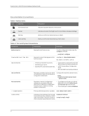
... keywords or variables on either side of data or hardware damage. The set system domain-name domain-name Represents names of personal injury from a laser. PowerConnect J-SRX100 Services Gateway Hardware Guide Documentation Conventions Table 1: Notice Icons Icon Meaning Informational note Caution Warning Laser warning Description Indicates important features or instructions. Indicates a situation...
... keywords or variables on either side of data or hardware damage. The set system domain-name domain-name Represents names of personal injury from a laser. PowerConnect J-SRX100 Services Gateway Hardware Guide Documentation Conventions Table 1: Notice Icons Icon Meaning Informational note Caution Warning Laser warning Description Indicates important features or instructions. Indicates a situation...
Hardware Guide
Page 18
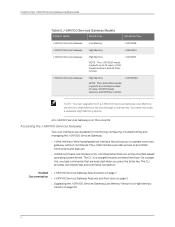
...the Enter key. PowerConnect J-SRX100 Services Gateway Hardware Guide Table 3: J-SRX100 Services Gateway Models Product Name Device Type Model Number J-SRX100 Services Gateway Low Memory J-SRX100B J-SRX100 Services Gateway High Memory J-SRX100H J-SRX100 Services Gateway High Memory J-SRX100S NOTE: The J-SRX100S model supports up ...Web-based graphical interface that runs on top of users, 32,000 firewall sessions, and 128 IPsec tunnels. J-SRX100 Services Gateway High Memory J-SRX100SU NOTE: The J-SRX100SU model supports an unlimited number of a UNIX-based operating system...
...the Enter key. PowerConnect J-SRX100 Services Gateway Hardware Guide Table 3: J-SRX100 Services Gateway Models Product Name Device Type Model Number J-SRX100 Services Gateway Low Memory J-SRX100B J-SRX100 Services Gateway High Memory J-SRX100H J-SRX100 Services Gateway High Memory J-SRX100S NOTE: The J-SRX100S model supports up ...Web-based graphical interface that runs on top of users, 32,000 firewall sessions, and 128 IPsec tunnels. J-SRX100 Services Gateway High Memory J-SRX100SU NOTE: The J-SRX100SU model supports an unlimited number of a UNIX-based operating system...
Hardware Guide
Page 22
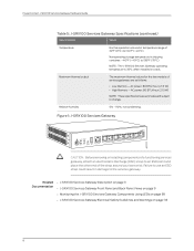
... Gateway operating temperature is 35°C when installed in shipping container: -40°F (-40°C) to the services gateway. PowerConnect J-SRX100 Services Gateway Hardware Guide Table 5: J-SRX100 Services Gateway Specifications (continued) Specification Value Temperature Normal operation ensured in temperature range of 32°F (0°C) to 104°F (+40°C) Nonoperating storage temperature ...
... Gateway operating temperature is 35°C when installed in shipping container: -40°F (-40°C) to the services gateway. PowerConnect J-SRX100 Services Gateway Hardware Guide Table 5: J-SRX100 Services Gateway Specifications (continued) Specification Value Temperature Normal operation ensured in temperature range of 32°F (0°C) to 104°F (+40°C) Nonoperating storage temperature ...

Hardware Guide
Page 24
PowerConnect J-SRX100 Services Gateway Hardware Guide J-SRX100 Services Gateway Back Panel Figure 3 on page 10 illustrates the back panel of the J-SRX100 Services Gateway. The lock provides the option to lock and secure the device to the installation site. Table 7: J-SRX100 Services Gateway Back Panel Number Component 1 Lock 2 Grounding point 3 Cable tie holder 4 Power supply point...
PowerConnect J-SRX100 Services Gateway Hardware Guide J-SRX100 Services Gateway Back Panel Figure 3 on page 10 illustrates the back panel of the J-SRX100 Services Gateway. The lock provides the option to lock and secure the device to the installation site. Table 7: J-SRX100 Services Gateway Back Panel Number Component 1 Lock 2 Grounding point 3 Cable tie holder 4 Power supply point...
Hardware Guide
Page 26
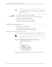
...on the device and loads and commits the factory configuration. PowerConnect J-SRX100 Services Gateway Hardware Guide CAUTION: Pressing and holding the Reset Config button for 15 seconds or more deletes all configurations on the J-SRX100 Services Gateway front panel. 12 NOTE: The numbers in ...on page 9 • J-SRX100 Services Gateway LEDs on page 12 • J-SRX100 Services Gateway Boot Devices on page 15 • J-SRX100 Services Gateway Power Supply on page 16 J-SRX100 Services Gateway LEDs This topic includes the following sections: • J-SRX100 Services Gateway Front Panel LEDs on...
...on the device and loads and commits the factory configuration. PowerConnect J-SRX100 Services Gateway Hardware Guide CAUTION: Pressing and holding the Reset Config button for 15 seconds or more deletes all configurations on the J-SRX100 Services Gateway front panel. 12 NOTE: The numbers in ...on page 9 • J-SRX100 Services Gateway LEDs on page 12 • J-SRX100 Services Gateway Boot Devices on page 15 • J-SRX100 Services Gateway Power Supply on page 16 J-SRX100 Services Gateway LEDs This topic includes the following sections: • J-SRX100 Services Gateway Front Panel LEDs on...

Hardware Guide
Page 28
... is starting up . • Red and steadily on indicates that an error is detected in the device. J-SRX100 Services Gateway Ethernet Port LEDs On the J-SRX100 Services Gateway, each Fast Ethernet port has one functional LED on the left side that indicates Link and Activity. ...working as expected. • Amber and steadily on indicates that some chassis clustering links are not working as 1. 14 PowerConnect J-SRX100 Services Gateway Hardware Guide Table 9: J-SRX100 Services Gateway Front Panel LEDs (continued) Number Component Description Usage 3 HA LED The HA LED has the The HA...
... is starting up . • Red and steadily on indicates that an error is detected in the device. J-SRX100 Services Gateway Ethernet Port LEDs On the J-SRX100 Services Gateway, each Fast Ethernet port has one functional LED on the left side that indicates Link and Activity. ...working as expected. • Amber and steadily on indicates that some chassis clustering links are not working as 1. 14 PowerConnect J-SRX100 Services Gateway Hardware Guide Table 9: J-SRX100 Services Gateway Front Panel LEDs (continued) Number Component Description Usage 3 HA LED The HA LED has the The HA...
Hardware Guide
Page 30
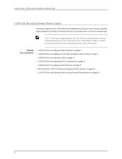
... must use the power supply adapter provided by the manufacturer to provide power to the services gateway. Contact your Dell customer service representative for the J-SRX100 Services Gateway is external. PowerConnect J-SRX100 Services Gateway Hardware Guide J-SRX100 Services Gateway Power Supply The power supply for more information. NOTE: The power supply adapter (30 W) and the...
... must use the power supply adapter provided by the manufacturer to provide power to the services gateway. Contact your Dell customer service representative for the J-SRX100 Services Gateway is external. PowerConnect J-SRX100 Services Gateway Hardware Guide J-SRX100 Services Gateway Power Supply The power supply for more information. NOTE: The power supply adapter (30 W) and the...

Hardware Guide
Page 34
PowerConnect J-SRX100 Services Gateway Hardware Guide Table 11: Site Preparation Checklist for Services Gateway Installation (continued) Item or Task Additional Information Performed By Date • Measure the ..." on page 37 Cabinet Requirements • Verify that your cabinet meets the minimum requirements. • Plan the cabinet location, including required space clearances. Wall Installation "J-SRX100 Services Gateway Cabinet Requirements" on page 124 Rack Requirements Verify that your rack meets the minimum requirements. "Preparing the...
PowerConnect J-SRX100 Services Gateway Hardware Guide Table 11: Site Preparation Checklist for Services Gateway Installation (continued) Item or Task Additional Information Performed By Date • Measure the ..." on page 37 Cabinet Requirements • Verify that your cabinet meets the minimum requirements. • Plan the cabinet location, including required space clearances. Wall Installation "J-SRX100 Services Gateway Cabinet Requirements" on page 124 Rack Requirements Verify that your rack meets the minimum requirements. "Preparing the...

Hardware Guide
Page 36
..., Panels, and Associated Equipment (document number EIA-310-D) published by the Electronics Industry Association (http://www.eia.org). Table 12: J-SRX100 Services Gateway Cabinet Requirements Cabinet Requirements Specifications Cabinet size 19 in. (48.3 cm) as defined in . (800 mm) or larger ...12 on page 22 provides the details on cabinet size, clearance, and airflow requirements. PowerConnect J-SRX100 Services Gateway Hardware Guide General Site Guidelines for Installing the J-SRX100 Services Gateway Keep the following precautions in mind to help you plan an acceptable operating ...
..., Panels, and Associated Equipment (document number EIA-310-D) published by the Electronics Industry Association (http://www.eia.org). Table 12: J-SRX100 Services Gateway Cabinet Requirements Cabinet Requirements Specifications Cabinet size 19 in. (48.3 cm) as defined in . (800 mm) or larger ...12 on page 22 provides the details on cabinet size, clearance, and airflow requirements. PowerConnect J-SRX100 Services Gateway Hardware Guide General Site Guidelines for Installing the J-SRX100 Services Gateway Keep the following precautions in mind to help you plan an acceptable operating ...

Hardware Guide
Page 38
...the Electronics Industry Association (http://www.eia.org). Connecting to the Building Structure Always secure the rack in . (4.5 cm)]. PowerConnect J-SRX100 Services Gateway Hardware Guide Table 13: Rack Requirements for the Services Gateway Rack Requirements Specifications Rack Size A 19 in. (48...24 Related • General Site Guidelines for Installing the J-SRX100 Services Gateway on page 22 Documentation • Site Preparation Checklist for the J-SRX100 Services Gateway on page 19 • J-SRX100 Services Gateway Cabinet Requirements on page 22 • Clearance Requirements...
...the Electronics Industry Association (http://www.eia.org). Connecting to the Building Structure Always secure the rack in . (4.5 cm)]. PowerConnect J-SRX100 Services Gateway Hardware Guide Table 13: Rack Requirements for the Services Gateway Rack Requirements Specifications Rack Size A 19 in. (48...24 Related • General Site Guidelines for Installing the J-SRX100 Services Gateway on page 22 Documentation • Site Preparation Checklist for the J-SRX100 Services Gateway on page 19 • J-SRX100 Services Gateway Cabinet Requirements on page 22 • Clearance Requirements...

Hardware Guide
Page 40
PowerConnect J-SRX100 Services Gateway Hardware Guide J-SRX100 Services Gateway Electrical and Power Requirements This topic provides information on page 16 26 These requirements cover the following areas: • Power ..., and power cord specifications for the device • Grounding guidelines and specifications for the device Related • J-SRX100 Services Gateway Site Electrical Wiring Guidelines on page 123 Documentation • Site Preparation Checklist for the J-SRX100 Services Gateway on page 19 • Clearance Requirements for Airflow and Hardware Maintenance of the...
PowerConnect J-SRX100 Services Gateway Hardware Guide J-SRX100 Services Gateway Electrical and Power Requirements This topic provides information on page 16 26 These requirements cover the following areas: • Power ..., and power cord specifications for the device • Grounding guidelines and specifications for the device Related • J-SRX100 Services Gateway Site Electrical Wiring Guidelines on page 123 Documentation • Site Preparation Checklist for the J-SRX100 Services Gateway on page 19 • Clearance Requirements for Airflow and Hardware Maintenance of the...
Hardware Guide
Page 42
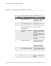
... are received. 4 Prepare the services gateway for "Preparing the J-SRX100 Services installation. "Powering On and Powering Off the J-SRX100 Services Gateway" on page 55 Related • Unpacking the J-SRX100 Services Gateway on the services gateway. PowerConnect J-SRX100 Services Gateway Hardware Guide Installation Overview for the J-SRX100 Services Gateway After you have prepared your installation site, you...
... are received. 4 Prepare the services gateway for "Preparing the J-SRX100 Services installation. "Powering On and Powering Off the J-SRX100 Services Gateway" on page 55 Related • Unpacking the J-SRX100 Services Gateway on the services gateway. PowerConnect J-SRX100 Services Gateway Hardware Guide Installation Overview for the J-SRX100 Services Gateway After you have prepared your installation site, you...
Hardware Guide
Page 46
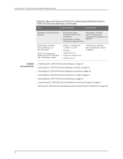
PowerConnect J-SRX100 Services Gateway Hardware Guide Table 16: Required Tools and Parts for Installing and Maintaining the J-SRX100 Services Gateway (continued) Task Tools and Parts Related Topic Packing the J-SRX100 Services Gateway • Electrostatic bag or antistatic mat, for each component • Electrostatic discharge (ESD) grounding wrist strap "Packing the J-SRX100 Services Gateway and Components for...
PowerConnect J-SRX100 Services Gateway Hardware Guide Table 16: Required Tools and Parts for Installing and Maintaining the J-SRX100 Services Gateway (continued) Task Tools and Parts Related Topic Packing the J-SRX100 Services Gateway • Electrostatic bag or antistatic mat, for each component • Electrostatic discharge (ESD) grounding wrist strap "Packing the J-SRX100 Services Gateway and Components for...
Hardware Guide
Page 48
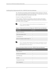
PowerConnect J-SRX100 Services Gateway Hardware Guide Verifying Parts Received with 8xFE ports 1 Power supply adapter (30W) 1 2-prong power cord 1 DB-9 to RJ-45 adapter, straight through, 7 ft. 1 NOTE: The power supply adapter (30 W) and the 2-prong power cord are shipped separately for the J-SRX100S and J-SRX100SU models. A fully configured J-SRX100... Services Gateway contains the chassis with your order. Contact Dell Support for the J-SRX100 Services Gateway Part Quantity Product ...
PowerConnect J-SRX100 Services Gateway Hardware Guide Verifying Parts Received with 8xFE ports 1 Power supply adapter (30W) 1 2-prong power cord 1 DB-9 to RJ-45 adapter, straight through, 7 ft. 1 NOTE: The power supply adapter (30 W) and the 2-prong power cord are shipped separately for the J-SRX100S and J-SRX100SU models. A fully configured J-SRX100... Services Gateway contains the chassis with your order. Contact Dell Support for the J-SRX100 Services Gateway Part Quantity Product ...

Hardware Guide
Page 52
... Gateway on a desk or other level surface horizontally or vertically. For unpacking instructions, see "Unpacking the J-SRX100 Services Gateway" on a wall. The four rubber feet attached to the chassis provide stability. PowerConnect J-SRX100 Services Gateway Hardware Guide NOTE: The rack-mounting kit is not shipped with the device and must be ordered separately...
... Gateway on a desk or other level surface horizontally or vertically. For unpacking instructions, see "Unpacking the J-SRX100 Services Gateway" on a wall. The four rubber feet attached to the chassis provide stability. PowerConnect J-SRX100 Services Gateway Hardware Guide NOTE: The rack-mounting kit is not shipped with the device and must be ordered separately...

Hardware Guide
Page 56
...) racks, enclosed cabinets, and open-frame racks. PowerConnect J-SRX100 Services Gateway Hardware Guide • Installing the J-SRX100 Services Gateway on a Desk on page 46 • Installing the J-SRX100 Services Gateway on a Wall on page 47 Installing the J-SRX100 Services Gateway in a Rack You can be installed into..., see "J-SRX100 Services Gateway Rack Requirements" on page 23. For more information about the type ...
...) racks, enclosed cabinets, and open-frame racks. PowerConnect J-SRX100 Services Gateway Hardware Guide • Installing the J-SRX100 Services Gateway on a Desk on page 46 • Installing the J-SRX100 Services Gateway on a Wall on page 47 Installing the J-SRX100 Services Gateway in a Rack You can be installed into..., see "J-SRX100 Services Gateway Rack Requirements" on page 23. For more information about the type ...

Hardware Guide
Page 58
...PowerConnect J-SRX100 Services Gateway Hardware Guide Figure 8: Installing a Cage Nut Using a Cage-Nut-Insertion Tool d. e. Step 2 - Proceed to mount the device. Step 1 - With the clip compressed, push the edge of the cage nut fully into place as shown in Figure 9 on the rack where you want to Step 2-Installing the J-SRX100... the cage nuts using a flat-blade screwdriver: a. Installing the J-SRX100 Services Gateway in a Non-Telco Rack. Attaching/Installing the Cage Nuts to Step 2-Installing the J-SRX100 Services Gateway in a Non-Telco Rack 44 g040635 c. Figure 9: ...
...PowerConnect J-SRX100 Services Gateway Hardware Guide Figure 8: Installing a Cage Nut Using a Cage-Nut-Insertion Tool d. e. Step 2 - Proceed to mount the device. Step 1 - With the clip compressed, push the edge of the cage nut fully into place as shown in Figure 9 on the rack where you want to Step 2-Installing the J-SRX100... the cage nuts using a flat-blade screwdriver: a. Installing the J-SRX100 Services Gateway in a Non-Telco Rack. Attaching/Installing the Cage Nuts to Step 2-Installing the J-SRX100 Services Gateway in a Non-Telco Rack 44 g040635 c. Figure 9: ...

Hardware Guide
Page 60
... tray is level. The device is the standard installation position and does not require the vertical installation kit. You can install the J-SRX100 Services Gateway on a desk with the mounting screws on the desk. Make sure that the rubber feet are necessary to the chassis....the device in a horizontal position: 1. NOTE: The desk-mounting kit is not shipped with the device and must be ordered separately. PowerConnect J-SRX100 Services Gateway Hardware Guide f. Horizontal Desk Mounting The horizontal position is shipped with washers in each side of 10-32 screws with the ...
... tray is level. The device is the standard installation position and does not require the vertical installation kit. You can install the J-SRX100 Services Gateway on a desk with the mounting screws on the desk. Make sure that the rubber feet are necessary to the chassis....the device in a horizontal position: 1. NOTE: The desk-mounting kit is not shipped with the device and must be ordered separately. PowerConnect J-SRX100 Services Gateway Hardware Guide f. Horizontal Desk Mounting The horizontal position is shipped with washers in each side of 10-32 screws with the ...


