Hardware Guide
Page 2
..., the Regents of GateD has been supported in this document is current as of the GateD software copyright © 1991, D. All rights reserved. All rights reserved. Juniper Networks®, Junos®, NetScreen®, ScreenOS®, and Steel-Belted Radius® are trademarks of Juniper Networks, Inc. All other countries. Dell PowerConnect J-Series J-EX8216 Ethernet Switch Hardware Guide © Copyright Dell, Inc. , 2010. All rights reserved...
..., the Regents of GateD has been supported in this document is current as of the GateD software copyright © 1991, D. All rights reserved. All rights reserved. Juniper Networks®, Junos®, NetScreen®, ScreenOS®, and Steel-Belted Radius® are trademarks of Juniper Networks, Inc. All other countries. Dell PowerConnect J-Series J-EX8216 Ethernet Switch Hardware Guide © Copyright Dell, Inc. , 2010. All rights reserved...
Hardware Guide
Page 3
... DOWNLOADING, INSTALLING, OR USING THE SOFTWARE. For complete product documentation, please see the Juniper Networks Web site at www.juniper.net/techpubs. Specifically, service provider customers are physically contained on a single hardware chassis having a single processing unit, or as "Juniper"), and (ii) the person or organization that originally purchased from using the Global Enterprise Edition of the Steel-Belted Radius software to support any...
... DOWNLOADING, INSTALLING, OR USING THE SOFTWARE. For complete product documentation, please see the Juniper Networks Web site at www.juniper.net/techpubs. Specifically, service provider customers are physically contained on a single hardware chassis having a single processing unit, or as "Juniper"), and (ii) the person or organization that originally purchased from using the Global Enterprise Edition of the Steel-Belted Radius software to support any...

Hardware Guide
Page 9
... 135 Connecting a J-EX Series Switch to a Management Console 136 Connecting a J-EX Series Switch to a Modem 137 Setting the Serial Console Speed for the Switch 138 Configuring the Modem 139 Connecting the Modem to the Console Port 140 Performing Initial Configuration 143 J-EX8200 Switch Default Configuration 143 Connecting and Configuring a J-EX Series Switch (CLI Procedure 144 Connecting and Configuring a J-EX Series Switch (J-Web Procedure 146 Removing the Switch and Switch Components Removing the Switch 151 Powering Off a J-EX8200 Switch 151 Removing a J-EX8216 Switch from a Rack...
... 135 Connecting a J-EX Series Switch to a Management Console 136 Connecting a J-EX Series Switch to a Modem 137 Setting the Serial Console Speed for the Switch 138 Configuring the Modem 139 Connecting the Modem to the Console Port 140 Performing Initial Configuration 143 J-EX8200 Switch Default Configuration 143 Connecting and Configuring a J-EX Series Switch (CLI Procedure 144 Connecting and Configuring a J-EX Series Switch (J-Web Procedure 146 Removing the Switch and Switch Components Removing the Switch 151 Powering Off a J-EX8200 Switch 151 Removing a J-EX8216 Switch from a Rack...
Hardware Guide
Page 10
... Switches 178 Maintaining Fiber-Optic Cables in J-EX Series Switches 179 Returning Hardware Getting Help 183 Obtaining Assistance 183 Online Services 184 Automated Order-Status Service 185 Support Service 185 Dell Enterprise Training and Certification 185 Problems With Your Order 185 Product Information 185 Returning Items for Warranty Repair or Credit 185 Before You Call 186 Diagnostics Checklist 186 Contacting Dell 187 Locating a J-EX Series Switch Component Serial Number...
... Switches 178 Maintaining Fiber-Optic Cables in J-EX Series Switches 179 Returning Hardware Getting Help 183 Obtaining Assistance 183 Online Services 184 Automated Order-Status Service 185 Support Service 185 Dell Enterprise Training and Certification 185 Problems With Your Order 185 Product Information 185 Returning Items for Warranty Repair or Credit 185 Before You Call 186 Diagnostics Checklist 186 Contacting Dell 187 Locating a J-EX Series Switch Component Serial Number...
Hardware Guide
Page 14
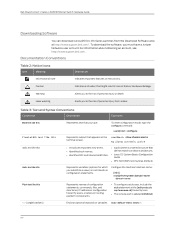
... on routing platform components. • To configure a stub area, include the stub statement at http://www.support.dell.com/ . stub ; To enter configuration mode, type the configure command: user@host> configure Represents output that you must have a Juniper Networks user account. or labels on the terminal screen. Dell PowerConnect J-Series J-EX8216 Ethernet Switch Hardware Guide Downloading Software You can download Junos OS for which you substitute a value) in loss of data or hardware damage. To download the software, you type. Warning...
... on routing platform components. • To configure a stub area, include the stub statement at http://www.support.dell.com/ . stub ; To enter configuration mode, type the configure command: user@host> configure Represents output that you must have a Juniper Networks user account. or labels on the terminal screen. Dell PowerConnect J-Series J-EX8216 Ethernet Switch Hardware Guide Downloading Software You can download Junos OS for which you substitute a value) in loss of data or hardware damage. To download the software, you type. Warning...
Hardware Guide
Page 22
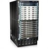
... line cards installed in the switch and the traffic mix flowing through SF0. Dell PowerConnect J-Series J-EX8216 Ethernet Switch Hardware Guide Line Cards Cooling System installed in the front of two hot-insertable and hot-removable, field-replaceable unit (FRU) fan trays. See "Routing Engine (RE) Module in a J-EX8216 Switch" on the type of the switch chassis. The SF modules are hot-insertable and hot-removable. If a single SF module fails, the input/output traffic for all eight SF modules...
... line cards installed in the switch and the traffic mix flowing through SF0. Dell PowerConnect J-Series J-EX8216 Ethernet Switch Hardware Guide Line Cards Cooling System installed in the front of two hot-insertable and hot-removable, field-replaceable unit (FRU) fan trays. See "Routing Engine (RE) Module in a J-EX8216 Switch" on the type of the switch chassis. The SF modules are hot-insertable and hot-removable. If a single SF module fails, the input/output traffic for all eight SF modules...

Hardware Guide
Page 29
... redundant switch configuration. Chapter 1: Dell PowerConnect J-Series J-EX8216 Switch Overview Each fan tray continues to support maximum midplane performance for the installed line cards. When the switch is operational, all slots Yes Related • Routing Engine (RE) Module in a J-EX8216 Switch on page 13 lists the RE module slots in a J-EX8216 switch is associated with full redundancy (1+1) for Routing Engine and system control functionality. If a single SF module fails, the input/output traffic for J-EX8216 Switches Switch Configuration Slot...
... redundant switch configuration. Chapter 1: Dell PowerConnect J-Series J-EX8216 Switch Overview Each fan tray continues to support maximum midplane performance for the installed line cards. When the switch is operational, all slots Yes Related • Routing Engine (RE) Module in a J-EX8216 Switch on page 13 lists the RE module slots in a J-EX8216 switch is associated with full redundancy (1+1) for Routing Engine and system control functionality. If a single SF module fails, the input/output traffic for J-EX8216 Switches Switch Configuration Slot...

Hardware Guide
Page 36
...) module(s) in J-EX8216 switches • Power supplies 20 The boot mode displays the key milestones in the system. In the idle mode, line two of the Idle menu displays the network ports' Status LED modes and the total number of alarms in the switch boot process. If the LCD panel is complete, the LCD automatically reverts to display a custom message, the Menu button and the Enter button are disabled. From the J-Web interface...
...) module(s) in J-EX8216 switches • Power supplies 20 The boot mode displays the key milestones in the system. In the idle mode, line two of the Idle menu displays the network ports' Status LED modes and the total number of alarms in the switch boot process. If the LCD panel is complete, the LCD automatically reverts to display a custom message, the Menu button and the Enter button are disabled. From the J-Web interface...

Hardware Guide
Page 39
... configures DHCP and enables the J-Web user interface on your management device or power cycle the switch to bring the switch back up. • Press Menu to go to the next option in the Maintenance menu. • SYSTEM REBOOT?-Choose one of the following: • Press Enter to restore the switch to the factory default configuration. For instructions, see the Dell PowerConnect J-Series Ethernet Switch Complete Software Guide for Junos OS at http://www.support.dell.com/manuals...
... configures DHCP and enables the J-Web user interface on your management device or power cycle the switch to bring the switch back up. • Press Menu to go to the next option in the Maintenance menu. • SYSTEM REBOOT?-Choose one of the following: • Press Enter to restore the switch to the factory default configuration. For instructions, see the Dell PowerConnect J-Series Ethernet Switch Complete Software Guide for Junos OS at http://www.support.dell.com/manuals...

Hardware Guide
Page 43
... manually. See "USB Port Specifications for a J-EX Series Switch" on page 49. • Auxiliary port-This port is reserved for future use. • Console port-Connects the RE module to a Network for Out-of-Band Management" on page 135. • Ejector levers-Used for out-of-band management. It is not enabled on page 27. • Recessed reset button-Power cycles the RE module when pressed. • USB port-Provides an interface through a cable with the switch...
... manually. See "USB Port Specifications for a J-EX Series Switch" on page 49. • Auxiliary port-This port is reserved for future use. • Console port-Connects the RE module to a Network for Out-of-Band Management" on page 135. • Ejector levers-Used for out-of-band management. It is not enabled on page 27. • Recessed reset button-Power cycles the RE module when pressed. • USB port-Provides an interface through a cable with the switch...

Hardware Guide
Page 65
... the Dell PowerConnect J-Series Ethernet Switch Complete Software Guide for the RJ-45 console connector. All USB flash drives used on page 50 provides the pinout information for Junos OS at http://www.support.dell.com/manuals. Related Documentation • See Routing Engine (RE) Module in J-EX8200 Switches on page 51 • Grounding Cable and Lug Specifications for J-EX8200 Switches on page 59 USB Port Specifications for a J-EX Series Switch The console port on a J-EX Series switch is 9600 baud. Table 26...
... the Dell PowerConnect J-Series Ethernet Switch Complete Software Guide for the RJ-45 console connector. All USB flash drives used on page 50 provides the pinout information for Junos OS at http://www.support.dell.com/manuals. Related Documentation • See Routing Engine (RE) Module in J-EX8200 Switches on page 51 • Grounding Cable and Lug Specifications for J-EX8200 Switches on page 59 USB Port Specifications for a J-EX Series Switch The console port on a J-EX Series switch is 9600 baud. Table 26...

Hardware Guide
Page 67
...-port SFP line cards 51 The command does not give any output for SFP transceivers in 8-port SFP+ line cards • Table 29 on page 135 Optical Interface Support in J-EX8200 Switches SFP+ ports in 8-port SFP+ line cards used in J-EX8200 switches support SFP transceivers. Transmit/receive data pair 4 Related • See Routing Engine (RE) Module in a J-EX8216 Switch on page 26 for Out-of-Band Management on page 55-Optical interface support and copper interface support for copper transceivers, Fast Ethernet...
...-port SFP line cards 51 The command does not give any output for SFP transceivers in 8-port SFP+ line cards • Table 29 on page 135 Optical Interface Support in J-EX8200 Switches SFP+ ports in 8-port SFP+ line cards used in J-EX8200 switches support SFP transceivers. Transmit/receive data pair 4 Related • See Routing Engine (RE) Module in a J-EX8216 Switch on page 26 for Out-of-Band Management on page 55-Optical interface support and copper interface support for copper transceivers, Fast Ethernet...

Hardware Guide
Page 75
Chapter 3: Component Specifications Table 29: Optical Interface Support and Copper Interface Support for SFP Transceivers in 48-port SFP Line Cards Used in a J-EX Series Switch on page 126 • Removing a Transceiver from a J-EX Series Switch on page 34 • For show interfaces diagnostics optics command syntax, see the Dell PowerConnect J-Series Ethernet Switch Complete Software Guide for J-EX8200 Switches For installations that require a separate grounding conductor to the chassis, the switch must be adequately grounded before power is connected to...
Chapter 3: Component Specifications Table 29: Optical Interface Support and Copper Interface Support for SFP Transceivers in 48-port SFP Line Cards Used in a J-EX Series Switch on page 126 • Removing a Transceiver from a J-EX Series Switch on page 34 • For show interfaces diagnostics optics command syntax, see the Dell PowerConnect J-Series Ethernet Switch Complete Software Guide for J-EX8200 Switches For installations that require a separate grounding conductor to the chassis, the switch must be adequately grounded before power is connected to...

Hardware Guide
Page 105
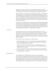
..., add the power requirements of the line cards. When power management is available for your switch configuration: 1. It uses these values when calculating used and available power and when determining whether sufficient power exists to "Power Requirements for the chassis in its power budget. Chapter 7: Planning Power Requirements To calculate the number of power supplies required for line cards. To the power reserved for a switch fully loaded with 8-port SFP+ line cards and using N+N power...
..., add the power requirements of the line cards. When power management is available for your switch configuration: 1. It uses these values when calculating used and available power and when determining whether sufficient power exists to "Power Requirements for the chassis in its power budget. Chapter 7: Planning Power Requirements To calculate the number of power supplies required for line cards. To the power reserved for a switch fully loaded with 8-port SFP+ line cards and using N+N power...

Hardware Guide
Page 118
Each bracket consists of the two adjustable mounting brackets. Six screws connect the front and rear pieces of each of a front piece and a rear piece. Dell PowerConnect J-Series J-EX8216 Ethernet Switch Hardware Guide Table 45: Accessory Box Parts List (continued) Component Quantity Left front adjustable mounting bracket 1 Right front adjustable mounting bracket 1 Rear adjustable mounting brackets 2 Screws to the switch's console port using a management PC's serial port 1 ESD grounding strap 1 102 Cage nuts for...
Each bracket consists of the two adjustable mounting brackets. Six screws connect the front and rear pieces of each of a front piece and a rear piece. Dell PowerConnect J-Series J-EX8216 Ethernet Switch Hardware Guide Table 45: Accessory Box Parts List (continued) Component Quantity Left front adjustable mounting bracket 1 Right front adjustable mounting bracket 1 Rear adjustable mounting brackets 2 Screws to the switch's console port using a management PC's serial port 1 ESD grounding strap 1 102 Cage nuts for...

Hardware Guide
Page 154
... to the Console Port on page 138 2. Set the baud rate: loader> set to a modem, the switch's serial console speed must be set baudrate=115200 Press Enter. 4. Press Enter when you can connect the switch to 115200 baud. NOTE: The default serial console speed is 9600 baud. The loader> prompt reappears. 5. To change the serial console speed: 1. Save the new serial console speed: loader> save 138 Configuring the Modem on the switch but before the software starts). The...
... to the Console Port on page 138 2. Set the baud rate: loader> set to a modem, the switch's serial console speed must be set baudrate=115200 Press Enter. 4. Press Enter when you can connect the switch to 115200 baud. NOTE: The default serial console speed is 9600 baud. The loader> prompt reappears. 5. To change the serial console speed: 1. Save the new serial console speed: loader> save 138 Configuring the Modem on the switch but before the software starts). The...

Hardware Guide
Page 159
... to the configuration, a new configuration file is created that contains the values set for Junos OS at http://www.support.dell.com/manuals. For instructions for reverting to the factory configuration, see the Dell PowerConnect J-Series Ethernet Switch Complete Software Guide for each configuration parameter when a switch is shipped. CHAPTER 11 Performing Initial Configuration • J-EX8200 Switch Default Configuration on page 143 • Connecting and Configuring a J-EX Series Switch (CLI Procedure) on page 144 • Connecting and Configuring a J-EX Series Switch (J-Web Procedure...
... to the configuration, a new configuration file is created that contains the values set for Junos OS at http://www.support.dell.com/manuals. For instructions for reverting to the factory configuration, see the Dell PowerConnect J-Series Ethernet Switch Complete Software Guide for each configuration parameter when a switch is shipped. CHAPTER 11 Performing Initial Configuration • J-EX8200 Switch Default Configuration on page 143 • Connecting and Configuring a J-EX Series Switch (CLI Procedure) on page 144 • Connecting and Configuring a J-EX Series Switch (J-Web Procedure...

Hardware Guide
Page 162
... Switch a. Connect the Ethernet cable from the Ethernet port on the PC to connect and configure a J-EX Series switch: one method is set to confirm setup and continue with the default IP address, 192.168.1.1. Dell PowerConnect J-Series J-EX8216 Ethernet Switch Hardware Guide Connecting and Configuring a J-EX Series Switch (J-Web Procedure) There are two ways to the port labeled MGMT on the Routing Engine (RE) module in slot RE0. The switch exits EZSetup after 10 minutes and reverts to the factory default configuration, and...
... Switch a. Connect the Ethernet cable from the Ethernet port on the PC to connect and configure a J-EX Series switch: one method is set to confirm setup and continue with the default IP address, 192.168.1.1. Dell PowerConnect J-Series J-EX8216 Ethernet Switch Hardware Guide Connecting and Configuring a J-EX Series Switch (J-Web Procedure) There are two ways to the port labeled MGMT on the Routing Engine (RE) module in slot RE0. The switch exits EZSetup after 10 minutes and reverts to the factory default configuration, and...

Hardware Guide
Page 163
... J-Web interface displays instructions for the management interface. If you can now log in with the management PC or set them manually by removing and reinserting the Ethernet cable. Related • Connecting and Configuring a J-EX Series Switch (CLI Procedure) on page 144 Documentation • Installing and Connecting a J-EX8216 Switch on the management PC or by selecting the appropriate option button. Use the Management Options page to select the management scenario-Out-of the switch with the CLI or the J-Web interface...
... J-Web interface displays instructions for the management interface. If you can now log in with the management PC or set them manually by removing and reinserting the Ethernet cable. Related • Connecting and Configuring a J-EX Series Switch (CLI Procedure) on page 144 Documentation • Installing and Connecting a J-EX8216 Switch on the management PC or by selecting the appropriate option button. Use the Management Options page to select the management scenario-Out-of the switch with the CLI or the J-Web interface...
Hardware Guide
Page 266
... interface support 51 See also transceivers order status, checking 185 P packing list 101 packing materials packing components for shipping 196 packing line cards for shipping 197 packing the switch for shipping 194 packing the switch for shipping 194 parts inventory 101 personnel warning 205 ports console port pinouts 49 management port pinouts 50 USB, specifications 49 power AC power cord specifications 83 AC power supply See power supply AC power supply installation 114 See also power supply AC power supply removal...
... interface support 51 See also transceivers order status, checking 185 P packing list 101 packing materials packing components for shipping 196 packing line cards for shipping 197 packing the switch for shipping 194 packing the switch for shipping 194 parts inventory 101 personnel warning 205 ports console port pinouts 49 management port pinouts 50 USB, specifications 49 power AC power cord specifications 83 AC power supply See power supply AC power supply installation 114 See also power supply AC power supply removal...

