Hardware Guide
Page 2
... reseller agreement or end-user purchase agreement executed between you and Juniper Networks. Reproduction of Juniper Networks, Inc. is automatically terminated. Juniper Networks assumes no part of GateD has been supported in the public domain. Dell PowerConnect J-Series J-EX8208 Ethernet Switch Hardware Guide © Copyright Dell, Inc. , 2010. SOFTWARE LICENSE The terms and conditions for further details. By using this software are described in the software license contained in this...
... reseller agreement or end-user purchase agreement executed between you and Juniper Networks. Reproduction of Juniper Networks, Inc. is automatically terminated. Juniper Networks assumes no part of GateD has been supported in the public domain. Dell PowerConnect J-Series J-EX8208 Ethernet Switch Hardware Guide © Copyright Dell, Inc. , 2010. SOFTWARE LICENSE The terms and conditions for further details. By using this software are described in the software license contained in this...
Hardware Guide
Page 3
... the Software after download, installation or use any commercial network access services. The foregoing license is granted herein to the Steel-Belted Radius or Odyssey Access Client software only, Customer shall use particular features, functionalities, services, applications, operations, or capabilities, or provide throughput, performance, configuration, bandwidth, interface, processing, temporal, or geographical limits. No license is not transferable or assignable by Customer only to manage access to support...
... the Software after download, installation or use any commercial network access services. The foregoing license is granted herein to the Steel-Belted Radius or Odyssey Access Client software only, Customer shall use particular features, functionalities, services, applications, operations, or capabilities, or provide throughput, performance, configuration, bandwidth, interface, processing, temporal, or geographical limits. No license is not transferable or assignable by Customer only to manage access to support...

Hardware Guide
Page 9
...EX Series Switch to a Modem 136 Setting the Serial Console Speed for the Switch 137 Configuring the Modem 138 Connecting the Modem to the Console Port 139 Connecting a J-EX Series Switch to a Network for Out-of-Band Management . . 140 Performing Initial Configuration 143 J-EX8200 Switch Default Configuration 143 Connecting and Configuring a J-EX Series Switch (CLI Procedure 144 Connecting and Configuring a J-EX Series Switch (J-Web Procedure 146 Removing the Switch and Switch Components Removing the Switch 151 Powering Off a J-EX8200 Switch 151 Removing a J-EX8208 Switch from a Rack...
...EX Series Switch to a Modem 136 Setting the Serial Console Speed for the Switch 137 Configuring the Modem 138 Connecting the Modem to the Console Port 139 Connecting a J-EX Series Switch to a Network for Out-of-Band Management . . 140 Performing Initial Configuration 143 J-EX8200 Switch Default Configuration 143 Connecting and Configuring a J-EX Series Switch (CLI Procedure 144 Connecting and Configuring a J-EX Series Switch (J-Web Procedure 146 Removing the Switch and Switch Components Removing the Switch 151 Powering Off a J-EX8200 Switch 151 Removing a J-EX8208 Switch from a Rack...
Hardware Guide
Page 10
... Switches 182 Maintaining Fiber-Optic Cables in J-EX Series Switches 183 Returning Hardware Getting Help 187 Obtaining Assistance 187 Online Services 188 Automated Order-Status Service 189 Support Service 189 Dell Enterprise Training and Certification 189 Problems With Your Order 189 Product Information 189 Returning Items for Warranty Repair or Credit 189 Before You Call 190 Diagnostics Checklist 190 Contacting Dell 191 Locating a J-EX Series Switch Component Serial Number...
... Switches 182 Maintaining Fiber-Optic Cables in J-EX Series Switches 183 Returning Hardware Getting Help 187 Obtaining Assistance 187 Online Services 188 Automated Order-Status Service 189 Support Service 189 Dell Enterprise Training and Certification 189 Problems With Your Order 189 Product Information 189 Returning Items for Warranty Repair or Credit 189 Before You Call 190 Diagnostics Checklist 190 Contacting Dell 191 Locating a J-EX Series Switch Component Serial Number...
Hardware Guide
Page 14
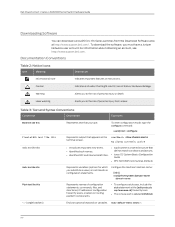
...] hierarchy level. • The console port is a named structure that you type. Configure the machine's domain name: [edit] root@# set system domain-name domain-name Represents names of data or hardware damage. or labels on the terminal screen. For information about obtaining an account, see http://www.support.dell.com. Table 3: Text and Syntax Conventions Convention Description Examples Bold text like this Fixed...
...] hierarchy level. • The console port is a named structure that you type. Configure the machine's domain name: [edit] root@# set system domain-name domain-name Represents names of data or hardware damage. or labels on the terminal screen. For information about obtaining an account, see http://www.support.dell.com. Table 3: Text and Syntax Conventions Convention Description Examples Bold text like this Fixed...

Hardware Guide
Page 26
... even when a single fan fails provided the room temperature is in the J-EX8208 chassis and the Routing Engine and control redundancy associated with no redundancy. Table 6 on page 38. Any two of the two functional modules becomes nonoperational, the third module takes over. Dell PowerConnect J-Series J-EX8208 Ethernet Switch Hardware Guide The fan tray continues to provide a working switch fabric with different SRE module and Switch Fabric (SF) module combinations. See "Cooling...
... even when a single fan fails provided the room temperature is in the J-EX8208 chassis and the Routing Engine and control redundancy associated with no redundancy. Table 6 on page 38. Any two of the two functional modules becomes nonoperational, the third module takes over. Dell PowerConnect J-Series J-EX8208 Ethernet Switch Hardware Guide The fan tray continues to provide a working switch fabric with different SRE module and Switch Fabric (SF) module combinations. See "Cooling...

Hardware Guide
Page 32
... can view real-time status information in J-EX8208 switches • Power supplies • Fan tray(s) and chassis temperature • Junos OS version installed 16 For more information, see the Dell PowerConnect J-Series Ethernet Switch Complete Software Guide for 60 seconds, the backlight turns off. The boot mode does not have any menu options. After the boot process is configured to the Idle menu. Dell PowerConnect J-Series J-EX8208 Ethernet Switch Hardware Guide Figure 5: LCD Panel in the switch boot process. The boot mode displays the key...
... can view real-time status information in J-EX8208 switches • Power supplies • Fan tray(s) and chassis temperature • Junos OS version installed 16 For more information, see the Dell PowerConnect J-Series Ethernet Switch Complete Software Guide for 60 seconds, the backlight turns off. The boot mode does not have any menu options. After the boot process is configured to the Idle menu. Dell PowerConnect J-Series J-EX8208 Ethernet Switch Hardware Guide Figure 5: LCD Panel in the switch boot process. The boot mode displays the key...

Hardware Guide
Page 35
... Status LEDs in a J-EX8200 Switch on page 20 Documentation • Field-Replaceable Units in the Maintenance menu. • ENTER EZSETUP?-Choose one of the LCD panel. To completely halt the switch, use Maintenance menu options, disable the entire menu or individual menu options. Press Enter on your management device or power cycle the switch to confirm the restoration. For instructions, see the Dell PowerConnect J-Series Ethernet Switch Complete Software Guide...
... Status LEDs in a J-EX8200 Switch on page 20 Documentation • Field-Replaceable Units in the Maintenance menu. • ENTER EZSETUP?-Choose one of the LCD panel. To completely halt the switch, use Maintenance menu options, disable the entire menu or individual menu options. Press Enter on your management device or power cycle the switch to confirm the restoration. For instructions, see the Dell PowerConnect J-Series Ethernet Switch Complete Software Guide...

Hardware Guide
Page 39
...-band management. See "Connecting a J-EX Series Switch to a system console through which you can install Junos OS manually. Table 13 on and off • Controls system resets and boot sequence for the switch • Monitors and controls the fan speed, power status for installing and removing the SRE module. • Captive screws-Secure the SRE module in place. Chapter 2: Component Descriptions • Powers the line cards on page 24 describes these components: • SRE module LEDs...
...-band management. See "Connecting a J-EX Series Switch to a system console through which you can install Junos OS manually. Table 13 on and off • Controls system resets and boot sequence for the switch • Monitors and controls the fan speed, power status for installing and removing the SRE module. • Captive screws-Secure the SRE module in place. Chapter 2: Component Descriptions • Powers the line cards on page 24 describes these components: • SRE module LEDs...

Hardware Guide
Page 59
... booting the switch from a software package installed on a USB flash drive, see the the Dell PowerConnect J-Series Ethernet Switch Complete Software Guide for Junos OS at http://www.support.dell.com/manuals. All USB flash drives used on a J-EX Series switch is 9600 baud. 43 We strongly recommend that uses an RJ-45 connector to connect to a console management device. Dell can provide only limited support for the console port is an RS-232 serial interface that you use only supported USB flash drives. The default baud rate...
... booting the switch from a software package installed on a USB flash drive, see the the Dell PowerConnect J-Series Ethernet Switch Complete Software Guide for Junos OS at http://www.support.dell.com/manuals. All USB flash drives used on a J-EX Series switch is 9600 baud. 43 We strongly recommend that uses an RJ-45 connector to connect to a console management device. Dell can provide only limited support for the console port is an RS-232 serial interface that you use only supported USB flash drives. The default baud rate...

Hardware Guide
Page 61
... operational mode CLI command show interfaces diagnostics. Transmit/receive data pair 4 Related • See Switch Fabric and Routing Engine (SRE) Module in a J-EX8208 Switch on page 22 Documentation for port location. • Connecting a J-EX Series Switch to a Network for Out-of-Band Management on page 46-Optical interface support for SFP+ transceivers in J-EX8200 switches support digital optical monitoring (DOM): you can view the diagnostic details for SFP transceivers: • Table 25 on page 140 Optical Interface Support...
... operational mode CLI command show interfaces diagnostics. Transmit/receive data pair 4 Related • See Switch Fabric and Routing Engine (SRE) Module in a J-EX8208 Switch on page 22 Documentation for port location. • Connecting a J-EX Series Switch to a Network for Out-of-Band Management on page 46-Optical interface support for SFP+ transceivers in J-EX8200 switches support digital optical monitoring (DOM): you can view the diagnostic details for SFP transceivers: • Table 25 on page 140 Optical Interface Support...

Hardware Guide
Page 69
Chapter 3: Component Specifications Table 26: Optical Interface Support and Copper Interface Support for SFP Transceivers in 48-port SFP Line Cards Used in a J-EX Series Switch on page 125 • Removing a Transceiver from a J-EX Series Switch on page 29 • For show interfaces diagnostics optics command syntax, see the Dell PowerConnect J-Series Ethernet Switch Complete Software Guide for J-EX8200 Switches For installations that require a separate grounding conductor to the chassis, the switch must be adequately grounded before power is connected to...
Chapter 3: Component Specifications Table 26: Optical Interface Support and Copper Interface Support for SFP Transceivers in 48-port SFP Line Cards Used in a J-EX Series Switch on page 125 • Removing a Transceiver from a J-EX Series Switch on page 29 • For show interfaces diagnostics optics command syntax, see the Dell PowerConnect J-Series Ethernet Switch Complete Software Guide for J-EX8200 Switches For installations that require a separate grounding conductor to the chassis, the switch must be adequately grounded before power is connected to...

Hardware Guide
Page 98
... Table 38 on page 82. It uses these values when calculating used and available power and when determining whether sufficient power exists to "Power Requirements for J-EX8208 Switch Components" on chassis components installed. 2. The watt values shown in its power budget. Dell PowerConnect J-Series J-EX8208 Ethernet Switch Hardware Guide To calculate the number of power that does not vary depending on page 76. For example, for a switch fully loaded with 8-port SFP+ line cards and using N+N power...
... Table 38 on page 82. It uses these values when calculating used and available power and when determining whether sufficient power exists to "Power Requirements for J-EX8208 Switch Components" on chassis components installed. 2. The watt values shown in its power budget. Dell PowerConnect J-Series J-EX8208 Ethernet Switch Hardware Guide To calculate the number of power that does not vary depending on page 76. For example, for a switch fully loaded with 8-port SFP+ line cards and using N+N power...

Hardware Guide
Page 110
... and Support Information 1 Registration and Software Updates for Your Dell PowerConnect J-Series Product 1 Open Source Code Notice 1 Ethernet cable, RJ-45/RJ-45, 4-pair stranded UTP, category #5 1 RJ-45 to female DB-9 cable, to connect to connect the front pieces and rear pieces of the adjustable mounting brackets for your rack or cabinet. Dell PowerConnect J-Series J-EX8208 Ethernet Switch Hardware Guide Table 41: Accessory Box Parts List (continued) Component Quantity Screws to the switch's console port using a management PC's serial port 1 ESD...
... and Support Information 1 Registration and Software Updates for Your Dell PowerConnect J-Series Product 1 Open Source Code Notice 1 Ethernet cable, RJ-45/RJ-45, 4-pair stranded UTP, category #5 1 RJ-45 to female DB-9 cable, to connect to connect the front pieces and rear pieces of the adjustable mounting brackets for your rack or cabinet. Dell PowerConnect J-Series J-EX8208 Ethernet Switch Hardware Guide Table 41: Accessory Box Parts List (continued) Component Quantity Screws to the switch's console port using a management PC's serial port 1 ESD...
Hardware Guide
Page 114
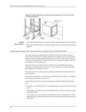
... and parts available to install the power cord tray: • A Phillips (+) screwdriver, number 1, 2, or 3, depending on the size of your rack requires them-of the appropriate size to attach the power cord tray to the rack (provided for a J-EX8200 Switch The power cord tray is supplied with all J-EX8200 switches. Dell PowerConnect J-Series J-EX8208 Ethernet Switch Hardware Guide Figure 37: Adjustable Mounting Brackets Installed in a Four-Post Rack (J-EX8208 Switch) Related Documentation • Mounting a J-EX8208 Switch on a Rack or Cabinet Using a Mechanical...
... and parts available to install the power cord tray: • A Phillips (+) screwdriver, number 1, 2, or 3, depending on the size of your rack requires them-of the appropriate size to attach the power cord tray to the rack (provided for a J-EX8200 Switch The power cord tray is supplied with all J-EX8200 switches. Dell PowerConnect J-Series J-EX8208 Ethernet Switch Hardware Guide Figure 37: Adjustable Mounting Brackets Installed in a Four-Post Rack (J-EX8208 Switch) Related Documentation • Mounting a J-EX8208 Switch on a Rack or Cabinet Using a Mechanical...
Hardware Guide
Page 159
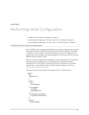
...://www.support.dell.com/manuals. You can always revert to the factory configuration, see the Dell PowerConnect J-Series Ethernet Switch Complete Software Guide for system parameters such as the ARP aging timer, the system log, and file messages, while also enabling the LLDP protocol, the RSTP protocol, IGMP snooping, and storm control. CHAPTER 11 Performing Initial Configuration • J-EX8200 Switch Default Configuration on page 143 • Connecting and Configuring a J-EX Series Switch (CLI Procedure) on page 144 • Connecting and Configuring a J-EX Series Switch (J-Web...
...://www.support.dell.com/manuals. You can always revert to the factory configuration, see the Dell PowerConnect J-Series Ethernet Switch Complete Software Guide for system parameters such as the ARP aging timer, the system log, and file messages, while also enabling the LLDP protocol, the RSTP protocol, IGMP snooping, and storm control. CHAPTER 11 Performing Initial Configuration • J-EX8200 Switch Default Configuration on page 143 • Connecting and Configuring a J-EX Series Switch (CLI Procedure) on page 144 • Connecting and Configuring a J-EX Series Switch (J-Web...

Hardware Guide
Page 162
... initial setup mode. This port is configured as an option in a J-EX8200 Switch a. Connect the Ethernet cable from the Ethernet port on the PC to the right of the LCD panel (see Figure 73 on the Switch Fabric and Routing Engine (SRE) module in the menu only when the switch is set to the switch. Dell PowerConnect J-Series J-EX8208 Ethernet Switch Hardware Guide Connecting and Configuring a J-EX Series Switch (J-Web Procedure) There are two ways to connect and configure a J-EX Series switch: one...
... initial setup mode. This port is configured as an option in a J-EX8200 Switch a. Connect the Ethernet cable from the Ethernet port on the PC to the right of the LCD panel (see Figure 73 on the Switch Fabric and Routing Engine (SRE) module in the menu only when the switch is set to the switch. Dell PowerConnect J-Series J-EX8208 Ethernet Switch Hardware Guide Connecting and Configuring a J-EX Series Switch (J-Web Procedure) There are two ways to connect and configure a J-EX Series switch: one...

Hardware Guide
Page 163
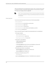
... Login. 5. Click Next. 9. Click Finish. If you may select options to enable Telnet, SSH, and SNMP services. NOTE: After the configuration is committed, the connectivity between the PC and the switch might be made, the J-Web interface displays instructions for the management interface. This is optional. • Enter a password and reenter the password. • Specify the time zone. • Synchronize the date and time settings of the switch with the CLI...
... Login. 5. Click Next. 9. Click Finish. If you may select options to enable Telnet, SSH, and SNMP services. NOTE: After the configuration is committed, the connectivity between the PC and the switch might be made, the J-Web interface displays instructions for the management interface. This is optional. • Enter a password and reenter the password. • Specify the time zone. • Synchronize the date and time settings of the switch with the CLI...
Hardware Guide
Page 204
... Caribbean countries) • http://www.dell.ca (Canada only) You can access Dell Support through the following services are not always available in as user: anonymous, and use your e-mail address as your Express Service Code to route the call directly to the proper support personnel. Dell PowerConnect J-Series J-EX8208 Ethernet Switch Hardware Guide Online Services When prompted by Dell's automated telephone system, enter your password. 188 For instructions on using the Dell Support, see "Support Service" on availability.
... Caribbean countries) • http://www.dell.ca (Canada only) You can access Dell Support through the following services are not always available in as user: anonymous, and use your e-mail address as your Express Service Code to route the call directly to the proper support personnel. Dell PowerConnect J-Series J-EX8208 Ethernet Switch Hardware Guide Online Services When prompted by Dell's automated telephone system, enter your password. 188 For instructions on using the Dell Support, see "Support Service" on availability.
Hardware Guide
Page 272
... fiber-optic cables 183 line card cables 182 line cards, handling 179 line cards, holding 180 line cards, storing 182 warnings 226 management console connection 135 management modem connection 136 management port LEDs 25 mechanical lift installation with 104 installation without 107 removal with 154 removal without 156 menus, LCD 17 modem connection configuring the modem 138 connecting 136 connecting to the console port 139 setting the serial console speed 137 modes, LCD 16 mounting brackets, installing 95 MST (Master) LED 20 N N+1 redundancy power supply configuration...
... fiber-optic cables 183 line card cables 182 line cards, handling 179 line cards, holding 180 line cards, storing 182 warnings 226 management console connection 135 management modem connection 136 management port LEDs 25 mechanical lift installation with 104 installation without 107 removal with 154 removal without 156 menus, LCD 17 modem connection configuring the modem 138 connecting 136 connecting to the console port 139 setting the serial console speed 137 modes, LCD 16 mounting brackets, installing 95 MST (Master) LED 20 N N+1 redundancy power supply configuration...

