
Hardware Guide
Page 2
... documentation were developed at private expense, and no responsibility for using this text: Dell™, the DELL™ logo, and PowerConnect™ are trademarks of Juniper Networks, Inc. All rights reserved. is subject to Juniper Networks: U.S. Trademarks used in this publication without notice. The Juniper Networks Logo, the Junos logo, and JunosE™ are trademarks of Dell Inc. Dell PowerConnect J-Series J-EX4200 Ethernet Switch Hardware Guide © Copyright Dell...
... documentation were developed at private expense, and no responsibility for using this text: Dell™, the DELL™ logo, and PowerConnect™ are trademarks of Juniper Networks, Inc. All rights reserved. is subject to Juniper Networks: U.S. Trademarks used in this publication without notice. The Juniper Networks Logo, the Junos logo, and JunosE™ are trademarks of Dell Inc. Dell PowerConnect J-Series J-EX4200 Ethernet Switch Hardware Guide © Copyright Dell...
Hardware Guide
Page 3
...") BEFORE DOWNLOADING, INSTALLING, OR USING THE SOFTWARE. Such limits may restrict use to a maximum number of seats, registered endpoints, concurrent users, sessions, calls, connections, subscribers, clusters, nodes, realms, devices, links, ports or transactions, or require the purchase of all such limitations and purchase of separate licenses to use particular features, functionalities, services, applications, operations, or capabilities, or provide throughput, performance, configuration, bandwidth, interface, processing...
...") BEFORE DOWNLOADING, INSTALLING, OR USING THE SOFTWARE. Such limits may restrict use to a maximum number of seats, registered endpoints, concurrent users, sessions, calls, connections, subscribers, clusters, nodes, realms, devices, links, ports or transactions, or require the purchase of all such limitations and purchase of separate licenses to use particular features, functionalities, services, applications, operations, or capabilities, or provide throughput, performance, configuration, bandwidth, interface, processing...
Hardware Guide
Page 20
... can add more member switches to the Virtual Chassis as a single chassis, called a Virtual Chassis. The switch remains operational if a single fan fails. • Redundant Routing Engines in the rack. Dell PowerConnect J-Series J-EX4200 Ethernet Switch Hardware Guide J-EX4200 Ethernet Switches have these features: • Run under Junos OS for J-EX Series switches • Have options of 24-port and 48-port models • Have options of full (all ports) or partial (8 ports) Power over Ethernet (PoE) capability...
... can add more member switches to the Virtual Chassis as a single chassis, called a Virtual Chassis. The switch remains operational if a single fan fails. • Redundant Routing Engines in the rack. Dell PowerConnect J-Series J-EX4200 Ethernet Switch Hardware Guide J-EX4200 Ethernet Switches have these features: • Run under Junos OS for J-EX Series switches • Have options of 24-port and 48-port models • Have options of full (all ports) or partial (8 ports) Power over Ethernet (PoE) capability...

Hardware Guide
Page 22
... a J-EX4200 switch with 24 Gigabit Ethernet ports. Figure 2 on page 7 shows the front panel of a J-EX4200 switch with 48 Gigabit Ethernet ports. Dell PowerConnect J-Series J-EX4200 Ethernet Switch Hardware Guide Table 5: Physical Specifications of the J-EX4200 Switch Chassis (continued) Description Value Chassis width Chassis depth • 17.25 in. (43.82 cm) • 19 in. (48.2 cm) with mounting brackets attached • Without power supply installed-17 in. (43.18 cm) • With power supply installed: • 320 W AC power supply installed...
... a J-EX4200 switch with 24 Gigabit Ethernet ports. Figure 2 on page 7 shows the front panel of a J-EX4200 switch with 48 Gigabit Ethernet ports. Dell PowerConnect J-Series J-EX4200 Ethernet Switch Hardware Guide Table 5: Physical Specifications of the J-EX4200 Switch Chassis (continued) Description Value Chassis width Chassis depth • 17.25 in. (43.82 cm) • 19 in. (48.2 cm) with mounting brackets attached • Without power supply installed-17 in. (43.18 cm) • With power supply installed: • 320 W AC power supply installed...
Hardware Guide
Page 24
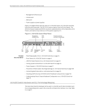
... 105 • Understanding Virtual Chassis Hardware Configuration on a J-EX4200 Switch on page 8 shows the rear panel of the power supply by 2.25 in . Dell PowerConnect J-Series J-EX4200 Ethernet Switch Hardware Guide • Management Ethernet port • Console port • ESD point • Power supply or power supplies Figure 4 on page 75 J-EX4200 Switch Hardware and CLI Terminology Mapping This topic describes the hardware terms used in J-EX4200 switch documentation and the corresponding terms used in the Junos OS command line interface (CLI). See Table 6 on page 9. 8
... 105 • Understanding Virtual Chassis Hardware Configuration on a J-EX4200 Switch on page 8 shows the rear panel of the power supply by 2.25 in . Dell PowerConnect J-Series J-EX4200 Ethernet Switch Hardware Guide • Management Ethernet port • Console port • ESD point • Power supply or power supplies Figure 4 on page 75 J-EX4200 Switch Hardware and CLI Terminology Mapping This topic describes the hardware terms used in J-EX4200 switch documentation and the corresponding terms used in the Junos OS command line interface (CLI). See Table 6 on page 9. 8
Hardware Guide
Page 31
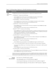
... the Dell PowerConnect J-Series Ethernet Switch Complete Software Guide for configuring the LCD panel on J-EX Series switches in the Maintenance menu. • LOAD RESCUE?-Choose one of the following: • Press the Enter button to restore the switch to the factory default configuration. Press the Enter button again to the System Halt option. If you delete the VCP, the port is in J-EX4200 Switches on page 16 • Connecting and Configuring a J-EX Series Switch (CLI...
... the Dell PowerConnect J-Series Ethernet Switch Complete Software Guide for configuring the LCD panel on J-EX Series switches in the Maintenance menu. • LOAD RESCUE?-Choose one of the following: • Press the Enter button to restore the switch to the factory default configuration. Press the Enter button again to the System Halt option. If you delete the VCP, the port is in J-EX4200 Switches on page 16 • Connecting and Configuring a J-EX Series Switch (CLI...

Hardware Guide
Page 33
... the network link and turns off the ALM LED. (See "Connecting a J-EX Series Switch to a Network for Out-of-Band Management" on page 120.) Connecting the switch to back it active on the switch and do not also create a rescue configuration to a dedicated management console instead of the three LEDs remotely through the CLI by issuing the operational mode command show chassis lcd. For more information, see the Dell PowerConnect J-Series Ethernet Switch Complete Software Guide for J-EX Series switches...
... the network link and turns off the ALM LED. (See "Connecting a J-EX Series Switch to a Network for Out-of-Band Management" on page 120.) Connecting the switch to back it active on the switch and do not also create a rescue configuration to a dedicated management console instead of the three LEDs remotely through the CLI by issuing the operational mode command show chassis lcd. For more information, see the Dell PowerConnect J-Series Ethernet Switch Complete Software Guide for J-EX Series switches...

Hardware Guide
Page 45
... the Dell PowerConnect J-Series Ethernet Switch Complete Software Guide for Junos OS at http://www.support.dell.com/manuals. 29 CHAPTER 3 Component Specifications • USB Port Specifications for a J-EX Series Switch on page 29 • Network Port Connector Pinout Information for a J-EX4200 Switch on page 30 • Console Port Connector Pinout Information for a J-EX Series Switch on page 30 • Management Port Connector Pinout Information for a J-EX4200 Switch on page 31 • Optical Interface Support in J-EX4200 Switches on page 32 • Uplink Modules Connector...
... the Dell PowerConnect J-Series Ethernet Switch Complete Software Guide for Junos OS at http://www.support.dell.com/manuals. 29 CHAPTER 3 Component Specifications • USB Port Specifications for a J-EX Series Switch on page 29 • Network Port Connector Pinout Information for a J-EX4200 Switch on page 30 • Console Port Connector Pinout Information for a J-EX Series Switch on page 30 • Management Port Connector Pinout Information for a J-EX4200 Switch on page 31 • Optical Interface Support in J-EX4200 Switches on page 32 • Uplink Modules Connector...

Hardware Guide
Page 57
...) uplink module on page 42 provides the uplink modules connector pinout information. 41 Chapter 3: Component Specifications Table 20: Optical Interface Support for Gigabit Ethernet SFP+ Transceivers in a J-EX Series Switch on page 110 • Removing a Transceiver from a J-EX Series Switch on page 144 Uplink Modules Connector Pinout Information for Junos OS at http://www.support.dell.com/manuals. • Installing a Transceiver in J-EX4200 Switches (continued) Ethernet Standard Specifications 10GBase-LR Model Number EX-SFP-10GE-LR Rate 10 Gbps Connector Type LC Fiber...
...) uplink module on page 42 provides the uplink modules connector pinout information. 41 Chapter 3: Component Specifications Table 20: Optical Interface Support for Gigabit Ethernet SFP+ Transceivers in a J-EX Series Switch on page 110 • Removing a Transceiver from a J-EX Series Switch on page 144 Uplink Modules Connector Pinout Information for Junos OS at http://www.support.dell.com/manuals. • Installing a Transceiver in J-EX4200 Switches (continued) Ethernet Standard Specifications 10GBase-LR Model Number EX-SFP-10GE-LR Rate 10 Gbps Connector Type LC Fiber...
Hardware Guide
Page 97
... use the autoprovisioning feature to add member switches to the factory defaults. For information about reverting to the factory default configuration, see the Dell PowerConnect J-Series Ethernet Switch Complete Software Guide for interconnecting with the new switch through an uplink module port by the master. • If you are expanding a preprovisioned configuration, made a note of the serial number (on the existing member switch. You can specify the role of the switch). To add a new member switch...
... use the autoprovisioning feature to add member switches to the factory defaults. For information about reverting to the factory default configuration, see the Dell PowerConnect J-Series Ethernet Switch Complete Software Guide for interconnecting with the new switch through an uplink module port by the master. • If you are expanding a preprovisioned configuration, made a note of the serial number (on the existing member switch. You can specify the role of the switch). To add a new member switch...

Hardware Guide
Page 98
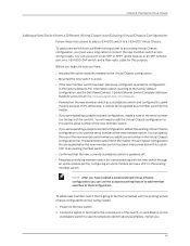
... http://www.support.dell.com/manuals. 82 Use the CLI or the J-Web interface to a J-EX4200 Virtual Chassis. Power on each of the Virtual Chassis configuration. Adding a New Switch to an Existing Preprovisioned Virtual Chassis Configuration Using Autoprovisioning Follow these instructions to add a J-EX4200 switch to set the uplink module ports as VCPs. Power off the new switch. 5. To configure LLDP, see see the Dell PowerConnect J-Series Ethernet Switch Complete Software Guide for the Virtual Chassis configuration. • Mounted the new switch in a rack. • Ensured...
... http://www.support.dell.com/manuals. 82 Use the CLI or the J-Web interface to a J-EX4200 Virtual Chassis. Power on each of the Virtual Chassis configuration. Adding a New Switch to an Existing Preprovisioned Virtual Chassis Configuration Using Autoprovisioning Follow these instructions to add a J-EX4200 switch to set the uplink module ports as VCPs. Power off the new switch. 5. To configure LLDP, see see the Dell PowerConnect J-Series Ethernet Switch Complete Software Guide for the Virtual Chassis configuration. • Mounted the new switch in a rack. • Ensured...
Hardware Guide
Page 99
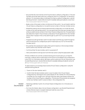
... existing preprovisioned Virtual Chassis configuration using the appropriate cable. To add a switch to the factory default configuration, see the Dell PowerConnect J-Series Ethernet Switch Complete Software Guide for Junos OS at http://www.support.dell.com/manuals. 83 Related • Replacing a Member Switch of a Virtual Chassis Configuration (CLI Procedure) on Documentation page 148 • For more information about setting an uplink module as a VCP on the existing member switch. • Ensured that the operational modes of the new member...
... existing preprovisioned Virtual Chassis configuration using the appropriate cable. To add a switch to the factory default configuration, see the Dell PowerConnect J-Series Ethernet Switch Complete Software Guide for Junos OS at http://www.support.dell.com/manuals. 83 Related • Replacing a Member Switch of a Virtual Chassis Configuration (CLI Procedure) on Documentation page 148 • For more information about setting an uplink module as a VCP on the existing member switch. • Ensured that the operational modes of the new member...
Hardware Guide
Page 106
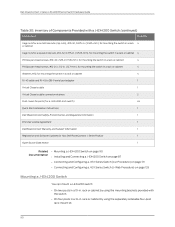
... switch) 24 Quick Start installation instructions 1 Dell PowerConnect Safety, Environmental, and Regulatory Information 1 End User License Agreement 1 DellPowerConnect Warranty and Support Information 1 Registration and Software Updates for Your Dell PowerConnect J-Series Product 1 Open Source Code Notice 1 Related • Mounting a J-EX4200 Switch on page 90 Documentation • Installing and Connecting a J-EX4200 Switch on page 87 • Connecting and Configuring a J-EX Series Switch (CLI Procedure) on page 131 • Connecting and Configuring a J-EX Series Switch (J-Web...
... switch) 24 Quick Start installation instructions 1 Dell PowerConnect Safety, Environmental, and Regulatory Information 1 End User License Agreement 1 DellPowerConnect Warranty and Support Information 1 Registration and Software Updates for Your Dell PowerConnect J-Series Product 1 Open Source Code Notice 1 Related • Mounting a J-EX4200 Switch on page 90 Documentation • Installing and Connecting a J-EX4200 Switch on page 87 • Connecting and Configuring a J-EX Series Switch (CLI Procedure) on page 131 • Connecting and Configuring a J-EX Series Switch (J-Web...
Hardware Guide
Page 135
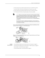
... a dedicated management console instead of -Band Management" on page 120.) Connecting the switch to an AC Power Supply in a J-EX4200 Switch Related • Connecting and Configuring a J-EX Series Switch (CLI Procedure) on page 131 Documentation • Connecting and Configuring a J-EX Series Switch (J-Web Procedure) on page 133 • Power Supply in J-EX4200 Switches on page 21 • AC Power Supply LEDs in J-EX4200 Switches on the switch completes the network link and turns off the ALM LED. (See "Connecting a J-EX Series Switch to a Network for Out-of a network does...
... a dedicated management console instead of -Band Management" on page 120.) Connecting the switch to an AC Power Supply in a J-EX4200 Switch Related • Connecting and Configuring a J-EX Series Switch (CLI Procedure) on page 131 Documentation • Connecting and Configuring a J-EX Series Switch (J-Web Procedure) on page 133 • Power Supply in J-EX4200 Switches on page 21 • AC Power Supply LEDs in J-EX4200 Switches on the switch completes the network link and turns off the ALM LED. (See "Connecting a J-EX Series Switch to a Network for Out-of a network does...
Hardware Guide
Page 138
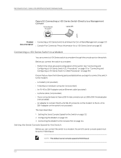
... parts available before you can connect a J-EX Series switch to a modem through the console port on the switch. NOTE: The default serial console speed is 9600 baud. 122 See "Connecting and Configuring a J-EX Series Switch (CLI Procedure)" on page 131 or "Connecting and Configuring a J-EX Series Switch (J-Web Procedure)" on page 122 2. Dell PowerConnect J-Series J-EX4200 Ethernet Switch Hardware Guide Figure 52: Connecting a J-EX Series Switch Directly to a Management Console Related • Connecting a J-EX Series Switch to a Network for Out-of the switch. Setting the Serial Console...
... parts available before you can connect a J-EX Series switch to a modem through the console port on the switch. NOTE: The default serial console speed is 9600 baud. 122 See "Connecting and Configuring a J-EX Series Switch (CLI Procedure)" on page 131 or "Connecting and Configuring a J-EX Series Switch (J-Web Procedure)" on page 122 2. Dell PowerConnect J-Series J-EX4200 Ethernet Switch Hardware Guide Figure 52: Connecting a J-EX Series Switch Directly to a Management Console Related • Connecting a J-EX Series Switch to a Network for Out-of the switch. Setting the Serial Console...

Hardware Guide
Page 143
...; Connecting and Configuring a J-EX Series Switch (J-Web Procedure) on page 133 • Setting the Mode on an SFP+ Uplink Module (CLI Procedure) on all interfaces; configures Power over Ethernet (PoE), storm control, and Ethernet switching on page 135 J-EX4200 Default Configuration Each J-EX Series switch is programmed with 24 ports (for models that contains the values set for both are the network interface ports. The following factory default configuration file is for a J-EX4200 switch with a factory default configuration that have more ports, this default configuration file has...
...; Connecting and Configuring a J-EX Series Switch (J-Web Procedure) on page 133 • Setting the Mode on an SFP+ Uplink Module (CLI Procedure) on all interfaces; configures Power over Ethernet (PoE), storm control, and Ethernet switching on page 135 J-EX4200 Default Configuration Each J-EX Series switch is programmed with 24 ports (for models that contains the values set for both are the network interface ports. The following factory default configuration file is for a J-EX4200 switch with a factory default configuration that have more ports, this default configuration file has...
Hardware Guide
Page 149
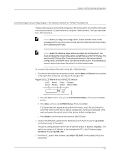
... initial setup mode. You must complete the initial configuration using the J-Web interface: 1. To transition the switch into initial setup mode, use the Menu and Enter buttons located to the right of the switch. EZSetup is displayed in the IP address range 192.168.1.2 through the console using the CLI and the other is using the J-Web interface. Connect the Ethernet cable from the Ethernet port on the PC to the factory default configuration. c. The switch exits EZSetup...
... initial setup mode. You must complete the initial configuration using the J-Web interface: 1. To transition the switch into initial setup mode, use the Menu and Enter buttons located to the right of the switch. EZSetup is displayed in the IP address range 192.168.1.2 through the console using the CLI and the other is using the J-Web interface. Connect the Ethernet cable from the Ethernet port on the PC to the factory default configuration. c. The switch exits EZSetup...

Hardware Guide
Page 173
...Problem The interface on the port in which an SFP or SFP+ transceiver is installed in an SFP+ uplink module installed in a J-EX4200 switch is incorrectly set. You must configure the operating mode of the SFP+ uplink module to match the type of transceiver you check the status with the J-Web user interface, the disabled port is not listed. Related • Troubleshooting Uplink Module Installation or Replacement on J-EX4200 Switches Documentation on page 158 • For information about J-EX4200 switch interfaces, interface configuration, and interface monitoring, see the Dell PowerConnect...
...Problem The interface on the port in which an SFP or SFP+ transceiver is installed in an SFP+ uplink module installed in a J-EX4200 switch is incorrectly set. You must configure the operating mode of the SFP+ uplink module to match the type of transceiver you check the status with the J-Web user interface, the disabled port is not listed. Related • Troubleshooting Uplink Module Installation or Replacement on J-EX4200 Switches Documentation on page 158 • For information about J-EX4200 switch interfaces, interface configuration, and interface monitoring, see the Dell PowerConnect...

Hardware Guide
Page 178
... addresses • mobile_support@us.dell.com • support@us.dell.com • la-techsupport@dell.com (Latin America and Caribbean countries only) • apsupport@dell.com (Asian/Pacific countries only) • Dell Marketing and Sales e-mail addresses • apmarketing@dell.com (Asian/Pacific countries only) • sales_canada@dell.com (Canada only) • Anonymous file transfer protocol (FTP) • ftp://ftp.dell.com Log in all locations outside the continental U.S. Dell PowerConnect J-Series J-EX4200 Ethernet Switch Hardware Guide Online Services...
... addresses • mobile_support@us.dell.com • support@us.dell.com • la-techsupport@dell.com (Latin America and Caribbean countries only) • apsupport@dell.com (Asian/Pacific countries only) • Dell Marketing and Sales e-mail addresses • apmarketing@dell.com (Asian/Pacific countries only) • sales_canada@dell.com (Canada only) • Anonymous file transfer protocol (FTP) • ftp://ftp.dell.com Log in all locations outside the continental U.S. Dell PowerConnect J-Series J-EX4200 Ethernet Switch Hardware Guide Online Services...
Hardware Guide
Page 235
... 175 product disposal 195 rack-mounting 185 ramps 184 read installation instructions 183 TN power system 202 wall installation 189 safety standards 207 seismic (earthquake), tested level 60 serial number chassis components, label 166 chassis, locating 165 fan tray 166 locating 165 power supply 166 uplink module 166 SFP transceivers list Fast Ethernet 38 Gigabit Ethernet 33 SFP uplink module description 26 port LEDs 18 SFP+ transceivers list Gigabit Ethernet 39 SFP+ uplink module description 26 port LEDs 18 setting the mode 135 shipping carton...
... 175 product disposal 195 rack-mounting 185 ramps 184 read installation instructions 183 TN power system 202 wall installation 189 safety standards 207 seismic (earthquake), tested level 60 serial number chassis components, label 166 chassis, locating 165 fan tray 166 locating 165 power supply 166 uplink module 166 SFP transceivers list Fast Ethernet 38 Gigabit Ethernet 33 SFP uplink module description 26 port LEDs 18 SFP+ transceivers list Gigabit Ethernet 39 SFP+ uplink module description 26 port LEDs 18 setting the mode 135 shipping carton...

