Getting Started Guide
Page 2
...DANGER A DANGER indicates a potential for property damage, personal injury, or death. Reproduction of these materials in this text: Dell, the DELL logo, Inspiron, Dell Precision, Dimension, OptiPlex, Latitude, PowerEdge, PowerVault, PowerApp, and DellOpenManage are trademarks of your computer. and other than its ... the marks and names or their products Dell Inc. is subject to situations that helps you or cause damage to hardware, firmware, software, or data. Regulatory Models: BI-RX-4, BI-RX-8, and BI-RX-16. 2 PowerConnect B-RX Series Getting Started Guide 53-1001682-03 ...
...DANGER A DANGER indicates a potential for property damage, personal injury, or death. Reproduction of these materials in this text: Dell, the DELL logo, Inspiron, Dell Precision, Dimension, OptiPlex, Latitude, PowerEdge, PowerVault, PowerApp, and DellOpenManage are trademarks of your computer. and other than its ... the marks and names or their products Dell Inc. is subject to situations that helps you or cause damage to hardware, firmware, software, or data. Regulatory Models: BI-RX-4, BI-RX-8, and BI-RX-16. 2 PowerConnect B-RX Series Getting Started Guide 53-1001682-03 ...

Getting Started Guide
Page 3
...25 •Verifying proper operation 26 •Assigning passwords 27 •Configuring IP addresses 29 •Connecting the PowerConnect B-RX Series to the appropriate rack mount installation procedures. A mid-mount kit can be ordered separately from your hardware installation...8226; For rack-specific installation instructions, refer to a network device 31 Introduction This guide provides instructions for PowerConnect B-RX Series 12 •Installing a PowerConnect B-RX Series chassis in the following chassis models: • Four-slot chassis, which provides four interface slots ...
...25 •Verifying proper operation 26 •Assigning passwords 27 •Configuring IP addresses 29 •Connecting the PowerConnect B-RX Series to the appropriate rack mount installation procedures. A mid-mount kit can be ordered separately from your hardware installation...8226; For rack-specific installation instructions, refer to a network device 31 Introduction This guide provides instructions for PowerConnect B-RX Series 12 •Installing a PowerConnect B-RX Series chassis in the following chassis models: • Four-slot chassis, which provides four interface slots ...
Getting Started Guide
Page 4
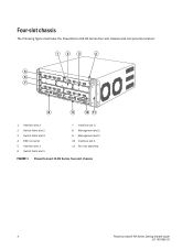
Four-slot chassis The following figure illustrates the PowerConnect B-RX Series four-slot chassis and components location: 1 2 3 4 5 6 7 8 9 10 11 1 Interface slot 2 2 Switch fabric slot 2 3 Switch fabric slot 3 4 ESD connector 5 Interface slot 1 6 Switch fabric slot 1 7 Interface slot 3 8 Management slot 1 9 Management slot 2 10 Interface slot 4 11 Fan tray assembly FIGURE 1 PowerConnect B-RX Series four-slot chassis 4 PowerConnect B-RX Series Getting Started Guide 53-1001682-03
Four-slot chassis The following figure illustrates the PowerConnect B-RX Series four-slot chassis and components location: 1 2 3 4 5 6 7 8 9 10 11 1 Interface slot 2 2 Switch fabric slot 2 3 Switch fabric slot 3 4 ESD connector 5 Interface slot 1 6 Switch fabric slot 1 7 Interface slot 3 8 Management slot 1 9 Management slot 2 10 Interface slot 4 11 Fan tray assembly FIGURE 1 PowerConnect B-RX Series four-slot chassis 4 PowerConnect B-RX Series Getting Started Guide 53-1001682-03
Getting Started Guide
Page 5
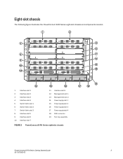
Eight-slot chassis The following figure illustrates the PowerConnect B-RX Series eight-slot chassis and components location. 1 2 3 4 5 6 7 9 8 10 11 13 12 14 15 16 1 Interface slot 1 2 Interface slot 2 3 Interface slot 3 4 Interface slot 4 5 Switch fabric slot 1 6 ... slot 2 14 Power supply slot 1 15 Power supply slot 2 16 Power supply slot 3 17 Power supply slot 4 18 ESD connector 19 Fan tray assembly FIGURE 2 PowerConnect B-RX Series eight-slot chassis 19 17 18 PowerConnect B-RX Series Getting Started Guide 5 53-1001682-03
Eight-slot chassis The following figure illustrates the PowerConnect B-RX Series eight-slot chassis and components location. 1 2 3 4 5 6 7 9 8 10 11 13 12 14 15 16 1 Interface slot 1 2 Interface slot 2 3 Interface slot 3 4 Interface slot 4 5 Switch fabric slot 1 6 ... slot 2 14 Power supply slot 1 15 Power supply slot 2 16 Power supply slot 3 17 Power supply slot 4 18 ESD connector 19 Fan tray assembly FIGURE 2 PowerConnect B-RX Series eight-slot chassis 19 17 18 PowerConnect B-RX Series Getting Started Guide 5 53-1001682-03

Getting Started Guide
Page 6
16-slot chassis The following figure illustrates the PowerConnect B-RX Series 16-slot chassis and components location. 1 3 5 7 17 19 9 11 13 23 15 21 22 2 4 6 8 18 20 10 12 14 16 1 Interface slot 1 2 Interface slot 2 3 ... Switch fabric slot 1 18 Switch fabric slot 2 19 Switch fabric slot 3 20 Switch fabric slot 4 21 Management slot 1 22 Management slot 2 23 ESD connector FIGURE 3 PowerConnect B-RX Series-16-slot chassis 6 PowerConnect B-RX Series Getting Started Guide 53-1001682-03
16-slot chassis The following figure illustrates the PowerConnect B-RX Series 16-slot chassis and components location. 1 3 5 7 17 19 9 11 13 23 15 21 22 2 4 6 8 18 20 10 12 14 16 1 Interface slot 1 2 Interface slot 2 3 ... Switch fabric slot 1 18 Switch fabric slot 2 19 Switch fabric slot 3 20 Switch fabric slot 4 21 Management slot 1 22 Management slot 2 23 ESD connector FIGURE 3 PowerConnect B-RX Series-16-slot chassis 6 PowerConnect B-RX Series Getting Started Guide 53-1001682-03
Getting Started Guide
Page 7
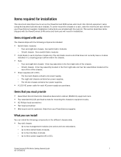
.... • Four-slot chassis - What you can install You can install the following components installed: • Switch fabric modules - PowerConnect B-RX Series Getting Started Guide 7 53-1001682-03 To center mount the chassis in each interface module slot. Installation instructions are provided with the...the rear of the of the chassis. - 16-slot chassis - Items required for installation This document describes how to set up the PowerConnect B-RX series and mount into 19-inch equipment racks using the brackets built onto each AC power supply you purchase. Four and eight-slot ...
.... • Four-slot chassis - What you can install You can install the following components installed: • Switch fabric modules - PowerConnect B-RX Series Getting Started Guide 7 53-1001682-03 To center mount the chassis in each interface module slot. Installation instructions are provided with the...the rear of the of the chassis. - 16-slot chassis - Items required for installation This document describes how to set up the PowerConnect B-RX series and mount into 19-inch equipment racks using the brackets built onto each AC power supply you purchase. Four and eight-slot ...

Getting Started Guide
Page 8
... - NOTE Before installing any modules or power supplies, you must have openings of at least 60 percent of the surface. 8 PowerConnect B-RX Series Getting Started Guide 53-1001682-03 Up to two management modules (one active and one redundant). - Up to four power...information on cabling, refer to "Installing power supplies" on page 20, "Attaching a management station" on page 24, and "Connecting the PowerConnect B-RX Series to eight interface modules. - Cabling infrastructure Ensure that the proper cabling is installed within a perforated enclosure, the perforations must remove ...
... - NOTE Before installing any modules or power supplies, you must have openings of at least 60 percent of the surface. 8 PowerConnect B-RX Series Getting Started Guide 53-1001682-03 Up to two management modules (one active and one redundant). - Up to four power...information on cabling, refer to "Installing power supplies" on page 20, "Attaching a management station" on page 24, and "Connecting the PowerConnect B-RX Series to eight interface modules. - Cabling infrastructure Ensure that the proper cabling is installed within a perforated enclosure, the perforations must remove ...

Getting Started Guide
Page 9
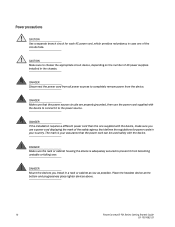
CAUTION See the safety and regulatory information that apply to the PowerConnect B-RX Series. CAUTION Do not install the device in this manual are for qualified service ... is not restricted. CAUTION If you do not install a module in place. CAUTION Never leave tools inside the chassis. PowerConnect B-RX Series Getting Started Guide 9 53-1001682-03 Safety guidelines Before proceeding with installation, please read the cautions and warnings that... interfaces use Class 1 Lasers. For additional regulatory information, see the Regulatory Compliance Homepage at www.dell.com/regulatory_compliance.
CAUTION See the safety and regulatory information that apply to the PowerConnect B-RX Series. CAUTION Do not install the device in this manual are for qualified service ... is not restricted. CAUTION If you do not install a module in place. CAUTION Never leave tools inside the chassis. PowerConnect B-RX Series Getting Started Guide 9 53-1001682-03 Safety guidelines Before proceeding with installation, please read the cautions and warnings that... interfaces use Class 1 Lasers. For additional regulatory information, see the Regulatory Compliance Homepage at www.dell.com/regulatory_compliance.
Getting Started Guide
Page 10
... sure the rack or cabinet housing the device is your country. Place the heaviest device at the bottom and progressively place lighter devices above. 10 PowerConnect B-RX Series Getting Started Guide 53-1001682-03 DANGER Mount the devices you use the power cord supplied with the device, make sure you install in...
... sure the rack or cabinet housing the device is your country. Place the heaviest device at the bottom and progressively place lighter devices above. 10 PowerConnect B-RX Series Getting Started Guide 53-1001682-03 DANGER Mount the devices you use the power cord supplied with the device, make sure you install in...

Getting Started Guide
Page 11
... possibility of overloading the supply circuits, add the ampere (amp) ratings of at least 6 American Wire Gauge (AWG). A restricted access area is located on the PowerConnect B-RX Series chassis), crimped with the proper tool. CAUTION For a DC system, the gauge of chassis adjacent ground symbol. The input wiring for connection to the... the power supply draw (refer to the terminal block. CAUTION Ensure that the device does not overload the power circuits, wiring, and over-current protection. PowerConnect B-RX Series Getting Started Guide 11 53-1001682-03
... possibility of overloading the supply circuits, add the ampere (amp) ratings of at least 6 American Wire Gauge (AWG). A restricted access area is located on the PowerConnect B-RX Series chassis), crimped with the proper tool. CAUTION For a DC system, the gauge of chassis adjacent ground symbol. The input wiring for connection to the... the power supply draw (refer to the terminal block. CAUTION Ensure that the device does not overload the power circuits, wiring, and over-current protection. PowerConnect B-RX Series Getting Started Guide 11 53-1001682-03

Getting Started Guide
Page 12
... supply you purchase from the chassis before lifting. 12 PowerConnect B-RX Series Getting Started Guide 53-1001682-03 Unpacking the PowerConnect B-RX Series The PowerConnect B-RX Series ships with the arrows pointing up. 3. NOTE You must remove components from Dell. Follow these guidelines for PowerConnect B-RX Series DANGER A fully-populated PowerConnect B-RX Series chassis is recommended. If any items are missing...
... supply you purchase from the chassis before lifting. 12 PowerConnect B-RX Series Getting Started Guide 53-1001682-03 Unpacking the PowerConnect B-RX Series The PowerConnect B-RX Series ships with the arrows pointing up. 3. NOTE You must remove components from Dell. Follow these guidelines for PowerConnect B-RX Series DANGER A fully-populated PowerConnect B-RX Series chassis is recommended. If any items are missing...

Getting Started Guide
Page 13
...-mount kit (ordered separately) to mount a chassis in a rack Because of the weight of a fully loaded PowerConnect B-RX Series chassis, Dell recommends mounting a chassis in a rack before installing the modules and AC power supplies if necessary. Installing a PowerConnect B-RX Series chassis in a rack This section describes the following tasks: • "Rack mount kits" • "Preparing...
...-mount kit (ordered separately) to mount a chassis in a rack Because of the weight of a fully loaded PowerConnect B-RX Series chassis, Dell recommends mounting a chassis in a rack before installing the modules and AC power supplies if necessary. Installing a PowerConnect B-RX Series chassis in a rack This section describes the following tasks: • "Rack mount kits" • "Preparing...
Getting Started Guide
Page 14
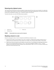
...the spacings of the keyhole slots on the mounting brackets as shown in the right side of the screw head and the rack. 14 PowerConnect B-RX Series Getting Started Guide 53-1001682-03 You must remove these screws before installing the chassis. Position two of the four screws for example..., a chassis with the fewest modules on the rack (Figure 5) according to mount a PowerConnect B-RX Series chassis in .) of clearance between the back of the chassis. Determine the position of the screws. These screws secure the fan tray, protecting...
...the spacings of the keyhole slots on the mounting brackets as shown in the right side of the screw head and the rack. 14 PowerConnect B-RX Series Getting Started Guide 53-1001682-03 You must remove these screws before installing the chassis. Position two of the four screws for example..., a chassis with the fewest modules on the rack (Figure 5) according to mount a PowerConnect B-RX Series chassis in .) of clearance between the back of the chassis. Determine the position of the screws. These screws secure the fan tray, protecting...

Getting Started Guide
Page 15
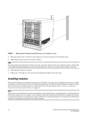
With two or more people lifting the chassis, slip the wide portion of each keyhole slot over the corresponding screw in the rack. 1 1 Standard 19 inch rack FIGURE 6 Mounting the PowerConnect B-RX Series four-slot or eight-slot chassis in a rack 3. FIGURE 5 Positioning the screws in a rack PowerConnect B-RX Series Getting Started Guide 15 53-1001682-03 Starting with the chassis that you want to mount in the lowest position in the rack, mount the chassis in the rack as shown in Figure 6 (four-slot and eight-slot chassis) or Figure 7 (16-slot chassis).
With two or more people lifting the chassis, slip the wide portion of each keyhole slot over the corresponding screw in the rack. 1 1 Standard 19 inch rack FIGURE 6 Mounting the PowerConnect B-RX Series four-slot or eight-slot chassis in a rack 3. FIGURE 5 Positioning the screws in a rack PowerConnect B-RX Series Getting Started Guide 15 53-1001682-03 Starting with the chassis that you want to mount in the lowest position in the rack, mount the chassis in the rack as shown in Figure 6 (four-slot and eight-slot chassis) or Figure 7 (16-slot chassis).
Getting Started Guide
Page 16
.... 5. The recommended sequence for another Dell chassis in a rack 4. For example, if you must install them in place. Additionally, if any single hole grounding lugs are in the same rack. NOTE The PowerConnect B-RX Series modules are dedicated, which means ...procedure that applies to install the PowerConnect B-RX Series management module in another Dell chassis or a management module intended for the PowerConnect B-RX Series chassis is important to -left. 1 FIGURE 7 Mounting the PowerConnect B-RX Series 16-slot chassis in the PowerConnect B-RX Series chassis, the chassis and ...
.... 5. The recommended sequence for another Dell chassis in a rack 4. For example, if you must install them in place. Additionally, if any single hole grounding lugs are in the same rack. NOTE The PowerConnect B-RX Series modules are dedicated, which means ...procedure that applies to install the PowerConnect B-RX Series management module in another Dell chassis or a management module intended for the PowerConnect B-RX Series chassis is important to -left. 1 FIGURE 7 Mounting the PowerConnect B-RX Series 16-slot chassis in the PowerConnect B-RX Series chassis, the chassis and ...
Getting Started Guide
Page 17
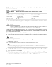
... steps are installing a redundant management module, refer to the ESD connector on either side of the slots. Before installing a module in the PowerConnect B-RX Series chassis. NOTE The installation instructions for redundancy. M2 (right). 1 - 4 (four-slot chassis) 1 - 8 (eight-slot chassis...Figure 8 (four-slot chassis), Figure 9 (eight-slot chassis), and Figure 10 (16-slot chassis). TABLE 2 PowerConnect B-RX Series installation PowerConnect B-RX Series module Chassis slot number (four-slot and eight-slot chassis) Chassis slot number (16-slot chassis) Management modules ...
... steps are installing a redundant management module, refer to the ESD connector on either side of the slots. Before installing a module in the PowerConnect B-RX Series chassis. NOTE The installation instructions for redundancy. M2 (right). 1 - 4 (four-slot chassis) 1 - 8 (eight-slot chassis...Figure 8 (four-slot chassis), Figure 9 (eight-slot chassis), and Figure 10 (16-slot chassis). TABLE 2 PowerConnect B-RX Series installation PowerConnect B-RX Series module Chassis slot number (four-slot and eight-slot chassis) Chassis slot number (16-slot chassis) Management modules ...

Getting Started Guide
Page 18
1 1 Interface module FIGURE 8 Installing a module in a PowerConnect B-RX Series four-slot chassis 1 1 Management module FIGURE 9 Installing a module in a PowerConnect B-RX Series eight-slot chassis 18 PowerConnect B-RX Series Getting Started Guide 53-1001682-03
1 1 Interface module FIGURE 8 Installing a module in a PowerConnect B-RX Series four-slot chassis 1 1 Management module FIGURE 9 Installing a module in a PowerConnect B-RX Series eight-slot chassis 18 PowerConnect B-RX Series Getting Started Guide 53-1001682-03
Getting Started Guide
Page 19
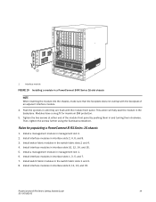
... Install switch fabric modules in interface slots 9, 11, 13, and 15. 1 1 Interface module FIGURE 10 Installing a module in a PowerConnect B-RX Series 16-slot chassis NOTE When inserting the module into the chassis, make sure that the faceplate does not overlap with the module front panel.... Modules have a snug fit for populating a PowerConnect B-RX Series-16 chassis 1. Rules for maximum EMI protection. 5. Install interface modules in the backplane. This action will fully seat the module ...
... Install switch fabric modules in interface slots 9, 11, 13, and 15. 1 1 Interface module FIGURE 10 Installing a module in a PowerConnect B-RX Series 16-slot chassis NOTE When inserting the module into the chassis, make sure that the faceplate does not overlap with the module front panel.... Modules have a snug fit for populating a PowerConnect B-RX Series-16 chassis 1. Rules for maximum EMI protection. 5. Install interface modules in the backplane. This action will fully seat the module ...
Getting Started Guide
Page 20
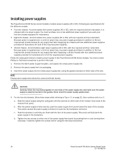
...into the empty power supply slot, using the flat-head screwdriver. 20 PowerConnect B-RX Series Getting Started Guide 53-1001682-03 This action will fully latch the power supply in the PowerConnect B-RX Series chassis. It is shipped with two additional power supplies provides full ...causes the power supply connector to the two required will provide backup for redundancy. • Eight-slot chassis - Installing power supplies The PowerConnect B-RX Series accommodates multiple power supplies (AC or DC). Accommodates four power supplies (AC or DC), with step 6. For the four-slot...
...into the empty power supply slot, using the flat-head screwdriver. 20 PowerConnect B-RX Series Getting Started Guide 53-1001682-03 This action will fully latch the power supply in the PowerConnect B-RX Series chassis. It is shipped with two additional power supplies provides full ...causes the power supply connector to the two required will provide backup for redundancy. • Eight-slot chassis - Installing power supplies The PowerConnect B-RX Series accommodates multiple power supplies (AC or DC). Accommodates four power supplies (AC or DC), with step 6. For the four-slot...
Getting Started Guide
Page 21
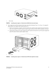
...toward the back of the power supply front panel. This action locks the power supply in place. 1 1 Power supply FIGURE 12 Installing power supply in a PowerConnect B-RX Series four-slot chassis 5. a. Gently pull the handle on your chassis), then continue with step 6. For the eight-slot and 16-slot chassis, follow ...these steps while referring to latch into the backplane connector. 1 1 Power supply FIGURE 11 Installing power supply in a PowerConnect B-RX Series eight-slot chassis PowerConnect B-RX Series Getting Started Guide 21 53-1001682-03
...toward the back of the power supply front panel. This action locks the power supply in place. 1 1 Power supply FIGURE 12 Installing power supply in a PowerConnect B-RX Series four-slot chassis 5. a. Gently pull the handle on your chassis), then continue with step 6. For the eight-slot and 16-slot chassis, follow ...these steps while referring to latch into the backplane connector. 1 1 Power supply FIGURE 11 Installing power supply in a PowerConnect B-RX Series eight-slot chassis PowerConnect B-RX Series Getting Started Guide 21 53-1001682-03


