Hardware Installation Guide
Page 3
... errors ix Contacting Dell ix Chapter 1 Product Overview Hardware features 1 Control features 3 Power supplies 13 Chapter 2 Installing the PowerConnect B-FCX Switch Unpacking the device 15 Package contents 15 General requirements 15 Installation tasks 16 Installation precautions 16 General precautions 17 Lifting precautions 17 Power precautions 17 Preparing the installation site 18 Cabling infrastructure 18 Installation location 18 Installing the device 19 Desktop installation 19 Rack mount installation 20 Connecting devices in a stack...
... errors ix Contacting Dell ix Chapter 1 Product Overview Hardware features 1 Control features 3 Power supplies 13 Chapter 2 Installing the PowerConnect B-FCX Switch Unpacking the device 15 Package contents 15 General requirements 15 Installation tasks 16 Installation precautions 16 General precautions 17 Lifting precautions 17 Power precautions 17 Preparing the installation site 18 Cabling infrastructure 18 Installation location 18 Installing the device 19 Desktop installation 19 Rack mount installation 20 Connecting devices in a stack...
Hardware Installation Guide
Page 4
... a lost password 34 Configuring IP addresses 35 Devices running Layer 2 software 35 Devices running Layer 3 software 36 Connecting network devices 39 Connectors 39 Cable specifications 39 Connecting to Ethernet or fast Ethernet hubs 39 Connecting to workstations, servers, or routers 40 Connecting a network device to a fiber port 40 Testing connectivity 43 Pinging an IP address 43 Observing LEDs 43 Tracing a route 45 Troubleshooting network connections 45 Using Virtual Cable Testing to diagnose a cable 46 Digital optical monitoring 47 Managing the PowerConnect B-FCX Hardware...
... a lost password 34 Configuring IP addresses 35 Devices running Layer 2 software 35 Devices running Layer 3 software 36 Connecting network devices 39 Connectors 39 Cable specifications 39 Connecting to Ethernet or fast Ethernet hubs 39 Connecting to workstations, servers, or routers 40 Connecting a network device to a fiber port 40 Testing connectivity 43 Pinging an IP address 43 Observing LEDs 43 Tracing a route 45 Troubleshooting network connections 45 Using Virtual Cable Testing to diagnose a cable 46 Digital optical monitoring 47 Managing the PowerConnect B-FCX Hardware...
Hardware Installation Guide
Page 8
... manual specifically notes those cases in which a command is often all lowercase. Contains the Simple Network Management Protocol (SNMP) Management Information Base (MIB) objects supported on de devices. DANGER A Danger statement indicates conditions or situations that can be potentially hazardous to you . Notes, cautions, and danger notices The following Dell documents supplement the information in this guide: • PowerConnect B-FCX Series Configuration Guide - For readability, command names...
... manual specifically notes those cases in which a command is often all lowercase. Contains the Simple Network Management Protocol (SNMP) Management Information Base (MIB) objects supported on de devices. DANGER A Danger statement indicates conditions or situations that can be potentially hazardous to you . Notes, cautions, and danger notices The following Dell documents supplement the information in this guide: • PowerConnect B-FCX Series Configuration Guide - For readability, command names...
Hardware Installation Guide
Page 9
...-effective. If you can find errors in the manuals, contact Dell Technical Support. In the Support menu, click All Support. Choose the method of these documents, which contain the most up-to-date information, refer to ensuring that is committed to Product Manuals at the bottom of countries and regions, click All. 3. PowerConnect B-FCX Switch Hardware Installation Guide ix 53-1002267-01 NOTE If...
...-effective. If you can find errors in the manuals, contact Dell Technical Support. In the Support menu, click All Support. Choose the method of these documents, which contain the most up-to-date information, refer to ensuring that is committed to Product Manuals at the bottom of countries and regions, click All. 3. PowerConnect B-FCX Switch Hardware Installation Guide ix 53-1002267-01 NOTE If...

Hardware Installation Guide
Page 13
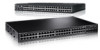
...WARNING POWER SUPPLY/FAN FRU TYPES MUST BE THE SAME AIRFLOW AIRFLOW Control features Each device front panel includes the following control features: • Serial management interface (the DB9 port labeled Console) PowerConnect B-FCX Switch Hardware Installation Guide 3 53-1002267-01 TABLE 1 Device Power supply and fan tray labels for PowerConnect B-FCX624-E, PowerConnect B-FCX624-I, PowerConnect B-FCX648-E, and PowerConnect B-FCX648-I devices Label on required power supply Label on required fan tray PowerConnect B-FCX624-E and PowerConnect B-FCX648-E WARNING E POWER SUPPLY/FAN...
...WARNING POWER SUPPLY/FAN FRU TYPES MUST BE THE SAME AIRFLOW AIRFLOW Control features Each device front panel includes the following control features: • Serial management interface (the DB9 port labeled Console) PowerConnect B-FCX Switch Hardware Installation Guide 3 53-1002267-01 TABLE 1 Device Power supply and fan tray labels for PowerConnect B-FCX624-E, PowerConnect B-FCX624-I, PowerConnect B-FCX648-E, and PowerConnect B-FCX648-I devices Label on required power supply Label on required fan tray PowerConnect B-FCX624-E and PowerConnect B-FCX648-E WARNING E POWER SUPPLY/FAN...
Hardware Installation Guide
Page 14
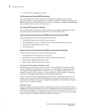
... required. 4 PowerConnect B-FCX Switch Hardware Installation Guide 53-1002267-01 The switch can also be configured to force the use of these ports does not support auto-negotiation, the communication mode of the RJ45 ports (ports 1~4). The serial management interface (the DB9 Console port) is located in a slot and has a valid link on its port, the associated RJ45 port is installed in the left corner of the front panel. Network interfaces for PowerConnect B-FCX624s and PowerConnect B-FCX648s PowerConnect B-FCX...
... required. 4 PowerConnect B-FCX Switch Hardware Installation Guide 53-1002267-01 The switch can also be configured to force the use of these ports does not support auto-negotiation, the communication mode of the RJ45 ports (ports 1~4). The serial management interface (the DB9 Console port) is located in a slot and has a valid link on its port, the associated RJ45 port is installed in the left corner of the front panel. Network interfaces for PowerConnect B-FCX624s and PowerConnect B-FCX648s PowerConnect B-FCX...

Hardware Installation Guide
Page 18
... SFF-8470 plug NOTE PowerConnect B-FCX624-E, PowerConnect B-FCX624-I, PowerConnect B-FCX648-E, and PowerConnect B-FCX648-I devices can be configured on these two ports in a stack) • Support for them to 3 meters. Cable specifications for key system and port indicators that simplifies installation and network troubleshooting. Port, system, and power status LEDs for PowerConnect B-FCX624s and PowerConnect B-FCX648s PowerConnect B-FCX switches include a display panel for CX4 stacking ports The following tables. 8 PowerConnect B-FCX Switch Hardware Installation Guide 53-1002267-01
... SFF-8470 plug NOTE PowerConnect B-FCX624-E, PowerConnect B-FCX624-I, PowerConnect B-FCX648-E, and PowerConnect B-FCX648-I devices can be configured on these two ports in a stack) • Support for them to 3 meters. Cable specifications for key system and port indicators that simplifies installation and network troubleshooting. Port, system, and power status LEDs for PowerConnect B-FCX624s and PowerConnect B-FCX648s PowerConnect B-FCX switches include a display panel for CX4 stacking ports The following tables. 8 PowerConnect B-FCX Switch Hardware Installation Guide 53-1002267-01

Hardware Installation Guide
Page 21
.... FIGURE 13 Port status LEDs 1 Reset 1 Console PS Mgmt 2 Diag 1 3 5 7 9 11 13 15 17 19 21 23 2 4 6 8 10 12 14 16 18 20 22 24 2 1 Port status LEDs 2 SFP or SFP+ port status LEDs TABLE 11 LED Port status LEDs Condition Ethernet (1~24/48) Link or Activity or Speed On/Flashing Green Off Status The port has established a valid link at 10/100/1000 Mbps. PowerConnect B-FCX Switch Hardware Installation Guide 11 53-1002267-01 A link is transmitting and receiving user packets. Hardware features 1 NOTE...
.... FIGURE 13 Port status LEDs 1 Reset 1 Console PS Mgmt 2 Diag 1 3 5 7 9 11 13 15 17 19 21 23 2 4 6 8 10 12 14 16 18 20 22 24 2 1 Port status LEDs 2 SFP or SFP+ port status LEDs TABLE 11 LED Port status LEDs Condition Ethernet (1~24/48) Link or Activity or Speed On/Flashing Green Off Status The port has established a valid link at 10/100/1000 Mbps. PowerConnect B-FCX Switch Hardware Installation Guide 11 53-1002267-01 A link is transmitting and receiving user packets. Hardware features 1 NOTE...

Hardware Installation Guide
Page 25
... devices ship with all of purchase. Connect the management station to the system. Chapter Installing the PowerConnect B-FCX Switch 2 CAUTION The procedures in "Power precautions" on the switch. C14) (for qualified service personnel. Use the serial connection to perform basic configuration tasks, including assigning an IP address and network mask to the Console serial port on page 17. PowerConnect B-FCX Switch Hardware Installation Guide 15 53-1002267-01 CAUTION Before beginning the...
... devices ship with all of purchase. Connect the management station to the system. Chapter Installing the PowerConnect B-FCX Switch 2 CAUTION The procedures in "Power precautions" on the switch. C14) (for qualified service personnel. Use the serial connection to perform basic configuration tasks, including assigning an IP address and network mask to the Console serial port on page 17. PowerConnect B-FCX Switch Hardware Installation Guide 15 53-1002267-01 CAUTION Before beginning the...

Hardware Installation Guide
Page 26
... the steps listed in Table 15 to the subnet on page 25 you power on the pages indicated. Subsequent IP address configuration can use provided retainer clips and screws). 4 Once the device is ready to configure the device through the Command Line Interface (CLI). 6 No default password is performed using the CLI or the Web PowerConnect B-FCX Series Configuration management interface. PowerConnect B-FCX Series Configuration Guide Installation precautions Follow all precautions when installing a Dell device. 16 PowerConnect B-FCX Switch Hardware Installation Guide 53...
... the steps listed in Table 15 to the subnet on page 25 you power on the pages indicated. Subsequent IP address configuration can use provided retainer clips and screws). 4 Once the device is ready to configure the device through the Command Line Interface (CLI). 6 No default password is performed using the CLI or the Web PowerConnect B-FCX Series Configuration management interface. PowerConnect B-FCX Series Configuration Guide Installation precautions Follow all precautions when installing a Dell device. 16 PowerConnect B-FCX Switch Hardware Installation Guide 53...
Hardware Installation Guide
Page 30
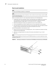
... for installation. 2 Preparing the installation site Rack mount installation NOTE You need a #2 Phillips screwdriver for PowerConnect B-FCX624s and PowerConnect B-FCX648s 20 PowerConnect B-FCX Switch Hardware Installation Guide 53-1002267-01 The kit contains two L-shaped mounting brackets and mounting screws. 2. Attach the mounting brackets to the Dell 1U shelf, Dell part number-G118R, which is not overloaded. • Grounding: Rack-mounted equipment should be properly grounded. NOTE For additional support for the stack of switches, refer...
... for installation. 2 Preparing the installation site Rack mount installation NOTE You need a #2 Phillips screwdriver for PowerConnect B-FCX624s and PowerConnect B-FCX648s 20 PowerConnect B-FCX Switch Hardware Installation Guide 53-1002267-01 The kit contains two L-shaped mounting brackets and mounting screws. 2. Attach the mounting brackets to the Dell 1U shelf, Dell part number-G118R, which is not overloaded. • Grounding: Rack-mounted equipment should be properly grounded. NOTE For additional support for the stack of switches, refer...

Hardware Installation Guide
Page 35
... appropriate cable for management by attaching a serial cable to the serial port of the system using a straight-through Telnet connections. Dell devices come with a standard male DB-9 connector, shown in the PowerConnect B-FCX Series Configuration Guide. Attaching a PC or terminal To assign an IP address, you can be easily accessible. NOTE If the outlet is a text-based interface that can access the system through a direct serial connection to the Command Line Interface (CLI). The serial port has...
... appropriate cable for management by attaching a serial cable to the serial port of the system using a straight-through Telnet connections. Dell devices come with a standard male DB-9 connector, shown in the PowerConnect B-FCX Series Configuration Guide. Attaching a PC or terminal To assign an IP address, you can be easily accessible. NOTE If the outlet is a text-based interface that can access the system through a direct serial connection to the Command Line Interface (CLI). The serial port has...
Hardware Installation Guide
Page 41
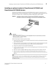
... Installing an optional module in PowerConnect B-FCX624 and PowerConnect B-FCX648 devices PowerConnect B-FCX624 and PowerConnect B-FCX648 switches support an optional four-port 1 Gbps SFP module or four-port 10 Gbps SFP+ module. Be sure to power-down your device in a stack. Perform these ports. For more information, see the PowerConnect B-FCX Series Configuration Guide PowerConnect B-FCX Switch Hardware Installation Guide 31 53-1002267-01 The 10 Gbps SFP+ module allows you to secure the module in "Port, system, and power status LEDs for PowerConnect B-FCX624 and PowerConnect B-FCX648...
... Installing an optional module in PowerConnect B-FCX624 and PowerConnect B-FCX648 devices PowerConnect B-FCX624 and PowerConnect B-FCX648 switches support an optional four-port 1 Gbps SFP module or four-port 10 Gbps SFP+ module. Be sure to power-down your device in a stack. Perform these ports. For more information, see the PowerConnect B-FCX Series Configuration Guide PowerConnect B-FCX Switch Hardware Installation Guide 31 53-1002267-01 The 10 Gbps SFP+ module allows you to secure the module in "Port, system, and power status LEDs for PowerConnect B-FCX624 and PowerConnect B-FCX648...

Hardware Installation Guide
Page 43
... Enable level and can assign passwords using the Web Management Interface. At this level, you can set the following access levels: • User EXEC - You can set other types of passwords. • Port Configuration - You can perform tasks such as manage files on the device. See the PowerConnect B-FCX Series Configuration Guide. You can be logged into the Privileged level of Enable passwords: • Super User - The CLI contains the following levels of the EXEC mode...
... Enable level and can assign passwords using the Web Management Interface. At this level, you can set the following access levels: • User EXEC - You can set other types of passwords. • Port Configuration - You can perform tasks such as manage files on the device. See the PowerConnect B-FCX Series Configuration Guide. You can be logged into the Privileged level of Enable passwords: • Super User - The CLI contains the following levels of the EXEC mode...

Hardware Installation Guide
Page 44
... a lost password. 1. NOTE Recovery from a lost password requires direct access to recover from a lost password" on page 34. Enter the following procedure to the serial port and a system reset. Use the following command to "Recovering from a lost , you can set the super user password before the initial system prompt appears, enter b to the Dell device. 2. At the opening CLI prompt, enter the following command to change to the device using the following command: PowerConnect# configure terminal PowerConnect(config...
... a lost password. 1. NOTE Recovery from a lost password requires direct access to recover from a lost password" on page 34. Enter the following procedure to the serial port and a system reset. Use the following command to "Recovering from a lost , you can set the super user password before the initial system prompt appears, enter b to the Dell device. 2. At the opening CLI prompt, enter the following command to change to the device using the following command: PowerConnect# configure terminal PowerConnect(config...

Hardware Installation Guide
Page 45
... networks. Access the configuration level of bits in the mask immediately after the IP address. PowerConnect(config)# ip address 192.22.3.44 255.255.255.0 5. Syntax: enable [] Syntax: configure terminal PowerConnect B-FCX Switch Hardware Installation Guide 35 53-1002267-01 Dell devices support both classical IP network masks (Class A, B, and C subnet masks, and so on a configured system, enter the write memory command to save the running Layer 2 software. 1. At the opening CLI prompt, enter enable. Set a default gateway address...
... networks. Access the configuration level of bits in the mask immediately after the IP address. PowerConnect(config)# ip address 192.22.3.44 255.255.255.0 5. Syntax: enable [] Syntax: configure terminal PowerConnect B-FCX Switch Hardware Installation Guide 35 53-1002267-01 Dell devices support both classical IP network masks (Class A, B, and C subnet masks, and so on a configured system, enter the write memory command to save the running Layer 2 software. 1. At the opening CLI prompt, enter enable. Set a default gateway address...

Hardware Installation Guide
Page 46
... serial connection to 64 IP subnet addresses per -interface table. PowerConnect> enable 2. Enter the following command: PowerConnect# configure terminalPrivileged EXEC Level PowerConnect(config)# Global CONFIG Level 4. Access the configuration level of the subnet-per port by increasing the size of the CLI by entering the following command at the CLI Privileged EXEC level prompt, then press Enter. In the above example, you must use the CLI through Telnet or the Web management interface. This command erases the factory test configuration...
... serial connection to 64 IP subnet addresses per -interface table. PowerConnect> enable 2. Enter the following command: PowerConnect# configure terminalPrivileged EXEC Level PowerConnect(config)# Global CONFIG Level 4. Access the configuration level of the subnet-per port by increasing the size of the CLI by entering the following command at the CLI Privileged EXEC level prompt, then press Enter. In the above example, you must use the CLI through Telnet or the Web management interface. This command erases the factory test configuration...

Hardware Installation Guide
Page 48
...interface number. Enter commands similar to the following to a VLAN and configure an IP address on the interface. The router-interface command creates virtual interface 1 as the routing interface for the virtual interface and assign an IP address to the VLAN. NOTE The switch uses the lowest MAC address on the device (the MAC address of untagged ports to the interface. PowerConnect(config)# vlan 2 name IP-Subnet_1.1.2.1/24 PowerConnect(config-vlan-2)# untag 1/1/1 to 1/1/4 PowerConnect(config-vlan-2)# router-interface ve1 PowerConnect(config-vlan-2)# interface ve1 PowerConnect(config...
...interface number. Enter commands similar to the following to a VLAN and configure an IP address on the interface. The router-interface command creates virtual interface 1 as the routing interface for the virtual interface and assign an IP address to the VLAN. NOTE The switch uses the lowest MAC address on the device (the MAC address of untagged ports to the interface. PowerConnect(config)# vlan 2 name IP-Subnet_1.1.2.1/24 PowerConnect(config-vlan-2)# untag 1/1/1 to 1/1/4 PowerConnect(config-vlan-2)# router-interface ve1 PowerConnect(config-vlan-2)# interface ve1 PowerConnect(config...

Hardware Installation Guide
Page 50
... need fiber cabling with an LC connector. Fiber cabling is required for stacking and non-stacking PowerConnect B-FCX models). Refer to "Connecting a network device to Gigabit NICs or switches and routers through UTP cabling is enabled on all 10/100 and Gigabit copper ports by default. Connecting a network device to a fiber port For direct attachment from the device to PowerConnect B-FCX Series Configuration Guide. For information about this feature and how configure it, refer to a Gbps NIC, switch, or router, using network interface cards...
... need fiber cabling with an LC connector. Fiber cabling is required for stacking and non-stacking PowerConnect B-FCX models). Refer to "Connecting a network device to Gigabit NICs or switches and routers through UTP cabling is enabled on all 10/100 and Gigabit copper ports by default. Connecting a network device to a fiber port For direct attachment from the device to PowerConnect B-FCX Series Configuration Guide. For information about this feature and how configure it, refer to a Gbps NIC, switch, or router, using network interface cards...
Hardware Installation Guide
Page 72
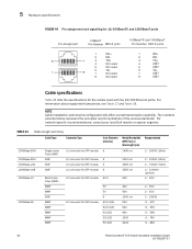
...) 2 - 10000 (10km) 2 - 70000 (70km) 2 - 120000 (120km) 2 - 550 2 - 550 2 - 550 2 - 10000 .5 - 275 .5 - 550 .5 - 595 .5 - 740 .5 - 860 62 PowerConnect B-FCX Switch Hardware Installation Guide 53-1002267-01 For network-specific recommendations, consult your local Dell reseller or system engineer. TABLE 24 Cable length summary Cable Type Connector Type Core Diameter (microns) Modal Bandwidth (MHz*km) or Wavelength (nm) Range (meters) 1000Base-BX-D 1000Base-BX-U 1000Base...
...) 2 - 10000 (10km) 2 - 70000 (70km) 2 - 120000 (120km) 2 - 550 2 - 550 2 - 550 2 - 10000 .5 - 275 .5 - 550 .5 - 595 .5 - 740 .5 - 860 62 PowerConnect B-FCX Switch Hardware Installation Guide 53-1002267-01 For network-specific recommendations, consult your local Dell reseller or system engineer. TABLE 24 Cable length summary Cable Type Connector Type Core Diameter (microns) Modal Bandwidth (MHz*km) or Wavelength (nm) Range (meters) 1000Base-BX-D 1000Base-BX-U 1000Base...

