Hardware Installation Guide
Page 3
... errors ix Contacting Dell ix Chapter 1 Product Overview Hardware features 1 Control features 3 Power supplies 13 Chapter 2 Installing the PowerConnect B-FCX Switch Unpacking the device 15 Package contents 15 General requirements 15 Installation tasks 16 Installation precautions 16 General precautions 17 Lifting precautions 17 Power precautions 17 Preparing the installation site 18 Cabling infrastructure 18 Installation location 18 Installing the device 19 Desktop installation 19 Rack mount installation 20 Connecting devices in a stack...
... errors ix Contacting Dell ix Chapter 1 Product Overview Hardware features 1 Control features 3 Power supplies 13 Chapter 2 Installing the PowerConnect B-FCX Switch Unpacking the device 15 Package contents 15 General requirements 15 Installation tasks 16 Installation precautions 16 General precautions 17 Lifting precautions 17 Power precautions 17 Preparing the installation site 18 Cabling infrastructure 18 Installation location 18 Installing the device 19 Desktop installation 19 Rack mount installation 20 Connecting devices in a stack...
Hardware Installation Guide
Page 4
... a lost password 34 Configuring IP addresses 35 Devices running Layer 2 software 35 Devices running Layer 3 software 36 Connecting network devices 39 Connectors 39 Cable specifications 39 Connecting to Ethernet or fast Ethernet hubs 39 Connecting to workstations, servers, or routers 40 Connecting a network device to a fiber port 40 Testing connectivity 43 Pinging an IP address 43 Observing LEDs 43 Tracing a route 45 Troubleshooting network connections 45 Using Virtual Cable Testing to diagnose a cable 46 Digital optical monitoring 47 Managing the PowerConnect B-FCX Hardware...
... a lost password 34 Configuring IP addresses 35 Devices running Layer 2 software 35 Devices running Layer 3 software 36 Connecting network devices 39 Connectors 39 Cable specifications 39 Connecting to Ethernet or fast Ethernet hubs 39 Connecting to workstations, servers, or routers 40 Connecting a network device to a fiber port 40 Testing connectivity 43 Pinging an IP address 43 Observing LEDs 43 Tracing a route 45 Troubleshooting network connections 45 Using Virtual Cable Testing to diagnose a cable 46 Digital optical monitoring 47 Managing the PowerConnect B-FCX Hardware...
Hardware Installation Guide
Page 8
... enterprise routing protocols. • PowerConnect B-MLXe MIB Reference - Safety labels are used in this manual. viii PowerConnect B-FCX Switch Hardware Installation Guide 53-1002267-01 Command syntax conventions The following conventions apply to warn of these conditions or situations. NOTE A note provides a tip, guidance or advice, emphasizes important information, or provides a reference to hardware, firmware, software, or data. Otherwise, this manual specifically notes those cases in which a command is...
... enterprise routing protocols. • PowerConnect B-MLXe MIB Reference - Safety labels are used in this manual. viii PowerConnect B-FCX Switch Hardware Installation Guide 53-1002267-01 Command syntax conventions The following conventions apply to warn of these conditions or situations. NOTE A note provides a tip, guidance or advice, emphasizes important information, or provides a reference to hardware, firmware, software, or data. Otherwise, this manual specifically notes those cases in which a command is...
Hardware Installation Guide
Page 9
PowerConnect B-FCX Switch Hardware Installation Guide ix 53-1002267-01 If you need assistance, or find contact information on your area. Click your investment in the manuals, contact Dell Technical Support. Choose the method of countries and regions, click All. 3. Contacting Dell For customers in your purchase invoice, packing slip, bill, or Dell product catalog. Dell provides several online and telephone-based...
PowerConnect B-FCX Switch Hardware Installation Guide ix 53-1002267-01 If you need assistance, or find contact information on your area. Click your investment in the manuals, contact Dell Technical Support. Choose the method of countries and regions, click All. 3. Contacting Dell For customers in your purchase invoice, packing slip, bill, or Dell product catalog. Dell provides several online and telephone-based...

Hardware Installation Guide
Page 13
... CAUTION For the PowerConnect B-FCX624-E, PowerConnect B-FCX624-I, PowerConnect B-FCX648-E , and PowerConnect B-FCX648-I WARNING POWER SUPPLY/FAN FRU TYPES MUST BE THE SAME AIRFLOW AIRFLOW Control features Each device front panel includes the following control features: • Serial management interface (the DB9 port labeled Console) PowerConnect B-FCX Switch Hardware Installation Guide 3 53-1002267-01 The power supplies and fan trays are clearly labeled with either a green arrow with an "E", or an orange arrow with an "I" as shown in Table 1.
... CAUTION For the PowerConnect B-FCX624-E, PowerConnect B-FCX624-I, PowerConnect B-FCX648-E , and PowerConnect B-FCX648-I WARNING POWER SUPPLY/FAN FRU TYPES MUST BE THE SAME AIRFLOW AIRFLOW Control features Each device front panel includes the following control features: • Serial management interface (the DB9 port labeled Console) PowerConnect B-FCX Switch Hardware Installation Guide 3 53-1002267-01 The power supplies and fan trays are clearly labeled with either a green arrow with an "E", or an orange arrow with an "I" as shown in Table 1.
Hardware Installation Guide
Page 14
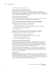
... 4-port 10Gbps Ethernet SFP+ module PowerConnect B-FCX 10/100/1000 BASE-T ports All PowerConnect B-FCX devices except for switch-to use straight-through cables for all ports support automatic MDI or MDI-X operation, you can be configured manually. If a device connected to other switches or hubs. Because all network connections to PCs or servers, or to one of these ports supports auto-negotiation, so the optimum transmission mode (half or full duplex), and the data rate (10...
... 4-port 10Gbps Ethernet SFP+ module PowerConnect B-FCX 10/100/1000 BASE-T ports All PowerConnect B-FCX devices except for switch-to use straight-through cables for all ports support automatic MDI or MDI-X operation, you can be configured manually. If a device connected to other switches or hubs. Because all network connections to PCs or servers, or to one of these ports supports auto-negotiation, so the optimum transmission mode (half or full duplex), and the data rate (10...

Hardware Installation Guide
Page 18
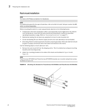
..., no connection exists, or the link is down . 1 Hardware features FIGURE 9 Four-port 10 Gbps SFP+ module FCX-4XG X1 X2 X3 X4 TABLE 6 LED Four-port 10 Gbps SFP+ module status LEDs Condition Status Link or Act LED (Link or On or flashing Green Port has a valid link at the global level and the stack disable CLI command must be entered at 10 Gbps. Activity) Off The link is connected. Cable specifications for CX4 stacking ports The following tables. 8 PowerConnect B-FCX Switch Hardware Installation Guide 53...
..., no connection exists, or the link is down . 1 Hardware features FIGURE 9 Four-port 10 Gbps SFP+ module FCX-4XG X1 X2 X3 X4 TABLE 6 LED Four-port 10 Gbps SFP+ module status LEDs Condition Status Link or Act LED (Link or On or flashing Green Port has a valid link at the global level and the stack disable CLI command must be entered at 10 Gbps. Activity) Off The link is connected. Cable specifications for CX4 stacking ports The following tables. 8 PowerConnect B-FCX Switch Hardware Installation Guide 53...

Hardware Installation Guide
Page 21
... for two installed power supply units LED PSU1 PSU2 Switch Status Load Sharing Four Green PSU LEDs AC OK DC OK Single Red 'DC OK' LED AC OK DC OK Both 'DC OK' LEDs Red AC OK DC OK One PSU with a remote port. PowerConnect B-FCX Switch Hardware Installation Guide 11 53-1002267-01 A link is transmitting and receiving user packets. TABLE 10 State Switch status for key system and port indicators that simplifies installation and network troubleshooting.
... for two installed power supply units LED PSU1 PSU2 Switch Status Load Sharing Four Green PSU LEDs AC OK DC OK Single Red 'DC OK' LED AC OK DC OK Both 'DC OK' LEDs Red AC OK DC OK One PSU with a remote port. PowerConnect B-FCX Switch Hardware Installation Guide 11 53-1002267-01 A link is transmitting and receiving user packets. TABLE 10 State Switch status for key system and port indicators that simplifies installation and network troubleshooting.

Hardware Installation Guide
Page 25
...-4 stacking cable • Rack mount kit • Document Kit • Rubber feet Kt • Retainer nuts and screws • Warranty card • A straight-through Telnet. Verify the contents of the items listed below. Connect the management station to build your shipping carton: • PowerConnect B-FCX device • 115V AC PDU power cords(C13- PowerConnect B-FCX Switch Hardware Installation Guide 15 53-1002267-01 C14) (for qualified service...
...-4 stacking cable • Rack mount kit • Document Kit • Rubber feet Kt • Retainer nuts and screws • Warranty card • A straight-through Telnet. Verify the contents of the items listed below. Connect the management station to build your shipping carton: • PowerConnect B-FCX device • 115V AC PDU power cords(C13- PowerConnect B-FCX Switch Hardware Installation Guide 15 53-1002267-01 C14) (for qualified service...

Hardware Installation Guide
Page 26
... the CLI. This will host the "Preparing the installation site" on device has the proper cabling and ventilation. running Layer 3 software" on page 37 9 Test IP connectivity to other devices by pinging them and "Testing connectivity" on the pages indicated. PowerConnect B-FCX Series Configuration Guide Installation precautions Follow all precautions when installing a Dell device. 16 PowerConnect B-FCX Switch Hardware Installation Guide 53-1002267-01 TABLE 15 Installation tasks Task Task Number Where...
... the CLI. This will host the "Preparing the installation site" on device has the proper cabling and ventilation. running Layer 3 software" on page 37 9 Test IP connectivity to other devices by pinging them and "Testing connectivity" on the pages indicated. PowerConnect B-FCX Series Configuration Guide Installation precautions Follow all precautions when installing a Dell device. 16 PowerConnect B-FCX Switch Hardware Installation Guide 53-1002267-01 TABLE 15 Installation tasks Task Task Number Where...
Hardware Installation Guide
Page 30
... stack of the device as shown in a rack, pay particular attention to the following setps to the sides of switches, refer to the mains. Before mounting the switch in Figure 20. Remove the rack mount kit from the shipping carton. Attach the mounting brackets to mount devices in Figure 19 and Figure 20. NOTE For additional support for PowerConnect B-FCX624s and PowerConnect B-FCX648s 20 PowerConnect B-FCX Switch Hardware Installation Guide...
... stack of the device as shown in a rack, pay particular attention to the following setps to the sides of switches, refer to the mains. Before mounting the switch in Figure 20. Remove the rack mount kit from the shipping carton. Attach the mounting brackets to mount devices in Figure 19 and Figure 20. NOTE For additional support for PowerConnect B-FCX624s and PowerConnect B-FCX648s 20 PowerConnect B-FCX Switch Hardware Installation Guide...

Hardware Installation Guide
Page 35
... easily accessible. Access the CLI by a PC or SNMP workstation. Attaching a PC or terminal 2 NOTE To turn the system off, simply unplug the power cable or cables. After you assign an IP address, you must have access to the serial port of the system using a straight-through Telnet connections. PowerConnect B-FCX Switch Hardware Installation Guide 25 53-1002267-01 The CLI is described in detail in Figure 26. Connect a PC or terminal to the Command Line Interface (CLI...
... easily accessible. Access the CLI by a PC or SNMP workstation. Attaching a PC or terminal 2 NOTE To turn the system off, simply unplug the power cable or cables. After you assign an IP address, you must have access to the serial port of the system using a straight-through Telnet connections. PowerConnect B-FCX Switch Hardware Installation Guide 25 53-1002267-01 The CLI is described in detail in Figure 26. Connect a PC or terminal to the Command Line Interface (CLI...
Hardware Installation Guide
Page 41
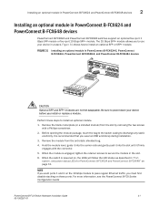
... first disable stacking on page 11. Figure 31 shows how to use your device before you wear an ESD wrist strap during installation. 3. Remove the blank metal plate (or a installed module) from the anti-static shielded bag. 4. When the module is recommended that you install or replace a module. FIGURE 31 Installing an optional module in PowerConnect B-FCX624 and PowerConnect B-FCX648 devices PowerConnect B-FCX624 and PowerConnect B-FCX648 switches support an optional four-port 1 Gbps SFP module...
... first disable stacking on page 11. Figure 31 shows how to use your device before you wear an ESD wrist strap during installation. 3. Remove the blank metal plate (or a installed module) from the anti-static shielded bag. 4. When the module is recommended that you install or replace a module. FIGURE 31 Installing an optional module in PowerConnect B-FCX624 and PowerConnect B-FCX648 devices PowerConnect B-FCX624 and PowerConnect B-FCX648 switches support an optional four-port 1 Gbps SFP module...

Hardware Installation Guide
Page 43
... as manage files on the device. PowerConnect B-FCX Switch Hardware Installation Guide 33 53-1002267-01 Allows complete read-and-write access to flash, and clear caches at this manual are for a Super User has been configured on the flash module, save the system configuration to the system. See the PowerConnect B-FCX Series Configuration Guide. To access the CONFIG mode, you can be logged into the Privileged level of passwords. • Port Configuration - Chapter Checking Network Devices and Testing Connectivity 3 CAUTION...
... as manage files on the device. PowerConnect B-FCX Switch Hardware Installation Guide 33 53-1002267-01 Allows complete read-and-write access to flash, and clear caches at this manual are for a Super User has been configured on the flash module, save the system configuration to the system. See the PowerConnect B-FCX Series Configuration Guide. To access the CONFIG mode, you can be logged into the Privileged level of passwords. • Port Configuration - Chapter Checking Network Devices and Testing Connectivity 3 CAUTION...

Hardware Installation Guide
Page 44
... console prompt reappears, assign a new password. 34 PowerConnect B-FCX Switch Hardware Installation Guide 53-1002267-01 Access the CONFIG level of the CLI by entering the following command to change to 32 characters long. Syntax: enable super-user-password | read -only-password NOTE If you can be up to the Privileged level of passwords. 4. NOTE Recovery from a lost password" on page 34. Start a CLI session over the serial interface to bypass the system password check...
... console prompt reappears, assign a new password. 34 PowerConnect B-FCX Switch Hardware Installation Guide 53-1002267-01 Access the CONFIG level of the CLI by entering the following command to change to 32 characters long. Syntax: enable super-user-password | read -only-password NOTE If you can be up to the Privileged level of passwords. 4. NOTE Recovery from a lost password" on page 34. Start a CLI session over the serial interface to bypass the system password check...

Hardware Installation Guide
Page 45
... save the running Layer 2 software. 1. At the opening CLI prompt, enter enable. PowerConnect(config)# ip address 192.22.3.44 255.255.255.0 5. Syntax: enable [] Syntax: configure terminal PowerConnect B-FCX Switch Hardware Installation Guide 35 53-1002267-01 See the PowerConnect B-FCX Series Configuration Guide. Set a default gateway address for the switch. Configure the IP address and mask for the switch. Devices running Layer 2 software Use the following procedure to configure an IP Address on a configured system, enter the write memory command to the startup-config file...
... save the running Layer 2 software. 1. At the opening CLI prompt, enter enable. PowerConnect(config)# ip address 192.22.3.44 255.255.255.0 5. Syntax: enable [] Syntax: configure terminal PowerConnect B-FCX Switch Hardware Installation Guide 35 53-1002267-01 See the PowerConnect B-FCX Series Configuration Guide. Set a default gateway address for the switch. Configure the IP address and mask for the switch. Devices running Layer 2 software Use the following procedure to configure an IP Address on a configured system, enter the write memory command to the startup-config file...

Hardware Installation Guide
Page 46
... configuration level of the CLI by increasing the size of the subnet-per-interface table. Syntax: enable [] Syntax: configure terminal Syntax: [no] ip address [secondary] or Syntax: [no ] ip address / Syntax: ip default-gateway Devices running configuration to the startup-config file. 3. PowerConnect(config)# int e 2 PowerConnect(config-if-e1000-2)# ip address 192.22.3.44 255.255.255.0 NOTE You can use the CLI through Telnet or the Web management interface. For subsequent addresses, you also can use the serial connection...
... configuration level of the CLI by increasing the size of the subnet-per-interface table. Syntax: enable [] Syntax: configure terminal Syntax: [no] ip address [secondary] or Syntax: [no ] ip address / Syntax: ip default-gateway Devices running configuration to the startup-config file. 3. PowerConnect(config)# int e 2 PowerConnect(config-if-e1000-2)# ip address 192.22.3.44 255.255.255.0 NOTE You can use the CLI through Telnet or the Web management interface. For subsequent addresses, you also can use the serial connection...

Hardware Installation Guide
Page 48
... 3 switch to route protocol traffic from 1 to the maximum number of virtual interfaces supported on the interface. Syntax: router-interface ve Syntax: interface ve Deleting an IP address Enter a command similar to the following to add a virtual interface to a VLAN and configure an IP address on the device. This section describes how to the interface. NOTE The switch uses the lowest MAC address on the device. PowerConnect(config)# vlan 2 name IP-Subnet_1.1.2.1/24 PowerConnect(config-vlan-2)# untag 1/1/1 to 1/1/4 PowerConnect(config-vlan-2)# router-interface ve1 PowerConnect(config...
... 3 switch to route protocol traffic from 1 to the maximum number of virtual interfaces supported on the interface. Syntax: router-interface ve Syntax: interface ve Deleting an IP address Enter a command similar to the following to add a virtual interface to a VLAN and configure an IP address on the device. This section describes how to the interface. NOTE The switch uses the lowest MAC address on the device. PowerConnect(config)# vlan 2 name IP-Subnet_1.1.2.1/24 PowerConnect(config-vlan-2)# untag 1/1/1 to 1/1/4 PowerConnect(config-vlan-2)# router-interface ve1 PowerConnect(config...

Hardware Installation Guide
Page 50
... Switch Hardware Installation Guide 53-1002267-01 This feature is required for stacking and non-stacking PowerConnect B-FCX models). For each port, you will need fiber cabling with an LC connector. For information about this feature and how configure it, refer to PowerConnect B-FCX Series Configuration Guide. Table 18 shows supported SFP and SFP+ transceivers. 3 Configuring IP addresses FIGURE 33 Straight-through cable g 10/100BASE-TX Straight-through Cable White/Orange Stripe Orange 1 End A 2 3 4 5 6 7 8 White/Green...
... Switch Hardware Installation Guide 53-1002267-01 This feature is required for stacking and non-stacking PowerConnect B-FCX models). For each port, you will need fiber cabling with an LC connector. For information about this feature and how configure it, refer to PowerConnect B-FCX Series Configuration Guide. Table 18 shows supported SFP and SFP+ transceivers. 3 Configuring IP addresses FIGURE 33 Straight-through cable g 10/100BASE-TX Straight-through Cable White/Orange Stripe Orange 1 End A 2 3 4 5 6 7 8 White/Green...
Hardware Installation Guide
Page 72
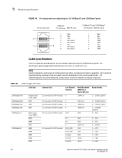
... Multi-mode Fiber (MMF) MMF MMF SMF MMF MMF MMF MMF MMF LC connector for SFP module 9 LC connector for SFP module 9 LC connector for SFP module 9 LC connector for SFP module 9 LC connector for SFP module 62.5 LC connector for the cables used with the 10/100 Ethernet ports. 5 Hardware specifications FIGURE 44 Pin assignment and signalling for 10/100BaseTX and 1000BaseT ports Pin Assignment 10BaseT Pin Number MDI-X ports...
... Multi-mode Fiber (MMF) MMF MMF SMF MMF MMF MMF MMF MMF LC connector for SFP module 9 LC connector for SFP module 9 LC connector for SFP module 9 LC connector for SFP module 9 LC connector for SFP module 62.5 LC connector for the cables used with the 10/100 Ethernet ports. 5 Hardware specifications FIGURE 44 Pin assignment and signalling for 10/100BaseTX and 1000BaseT ports Pin Assignment 10BaseT Pin Number MDI-X ports...

