Hardware Installation Guide
Page 3
... errors ix Contacting Dell ix Chapter 1 Product Overview Hardware features 1 Control features 3 Power supplies 13 Chapter 2 Installing the PowerConnect B-FCX Switch Unpacking the device 15 Package contents 15 General requirements 15 Installation tasks 16 Installation precautions 16 General precautions 17 Lifting precautions 17 Power precautions 17 Preparing the installation site 18 Cabling infrastructure 18 Installation location 18 Installing the device 19 Desktop installation 19 Rack mount installation 20 Connecting devices in a stack...
... errors ix Contacting Dell ix Chapter 1 Product Overview Hardware features 1 Control features 3 Power supplies 13 Chapter 2 Installing the PowerConnect B-FCX Switch Unpacking the device 15 Package contents 15 General requirements 15 Installation tasks 16 Installation precautions 16 General precautions 17 Lifting precautions 17 Power precautions 17 Preparing the installation site 18 Cabling infrastructure 18 Installation location 18 Installing the device 19 Desktop installation 19 Rack mount installation 20 Connecting devices in a stack...
Hardware Installation Guide
Page 4
... a lost password 34 Configuring IP addresses 35 Devices running Layer 2 software 35 Devices running Layer 3 software 36 Connecting network devices 39 Connectors 39 Cable specifications 39 Connecting to Ethernet or fast Ethernet hubs 39 Connecting to workstations, servers, or routers 40 Connecting a network device to a fiber port 40 Testing connectivity 43 Pinging an IP address 43 Observing LEDs 43 Tracing a route 45 Troubleshooting network connections 45 Using Virtual Cable Testing to diagnose a cable 46 Digital optical monitoring 47 Managing the PowerConnect B-FCX Hardware...
... a lost password 34 Configuring IP addresses 35 Devices running Layer 2 software 35 Devices running Layer 3 software 36 Connecting network devices 39 Connectors 39 Cable specifications 39 Connecting to Ethernet or fast Ethernet hubs 39 Connecting to workstations, servers, or routers 40 Connecting a network device to a fiber port 40 Testing connectivity 43 Pinging an IP address 43 Observing LEDs 43 Tracing a route 45 Troubleshooting network connections 45 Using Virtual Cable Testing to diagnose a cable 46 Digital optical monitoring 47 Managing the PowerConnect B-FCX Hardware...
Hardware Installation Guide
Page 8
... enterprise routing protocols. • PowerConnect B-MLXe MIB Reference - Contains the Simple Network Management Protocol (SNMP) Management Information Base (MIB) objects supported on de devices. DANGER A Danger statement indicates conditions or situations that can be potentially hazardous to you . Related publications The following note, cautions, and danger statements are printed in bold. Otherwise, this manual specifically notes those cases in which a command is...
... enterprise routing protocols. • PowerConnect B-MLXe MIB Reference - Contains the Simple Network Management Protocol (SNMP) Management Information Base (MIB) objects supported on de devices. DANGER A Danger statement indicates conditions or situations that can be potentially hazardous to you . Related publications The following note, cautions, and danger statements are printed in bold. Otherwise, this manual specifically notes those cases in which a command is...
Hardware Installation Guide
Page 9
... information on your country or region at support.dell.com. To contact Dell for you. For a full listing of countries and regions, click All. 3. PowerConnect B-FCX Switch Hardware Installation Guide ix 53-1002267-01 Availability varies by country and product, and some services may not be available in the United States, call 800-WWW.DELL (800.999.3355). Choose the method of...
... information on your country or region at support.dell.com. To contact Dell for you. For a full listing of countries and regions, click All. 3. PowerConnect B-FCX Switch Hardware Installation Guide ix 53-1002267-01 Availability varies by country and product, and some services may not be available in the United States, call 800-WWW.DELL (800.999.3355). Choose the method of...

Hardware Installation Guide
Page 13
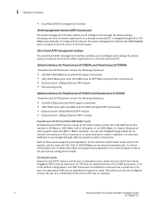
... B-FCX624-I, PowerConnect B-FCX648-E, and PowerConnect B-FCX648-I devices Label on required power supply Label on required fan tray PowerConnect B-FCX624-E and PowerConnect B-FCX648-E WARNING E POWER SUPPLY/FAN FRU TYPES MUST BE THE SAME AIRFLOW E AIRFLOW PowerConnect B-FCX624-I and PowerConnect B-FCX648-I WARNING POWER SUPPLY/FAN FRU TYPES MUST BE THE SAME AIRFLOW AIRFLOW Control features Each device front panel includes the following control features: • Serial management interface (the DB9 port labeled Console) PowerConnect B-FCX Switch Hardware Installation Guide...
... B-FCX624-I, PowerConnect B-FCX648-E, and PowerConnect B-FCX648-I devices Label on required power supply Label on required fan tray PowerConnect B-FCX624-E and PowerConnect B-FCX648-E WARNING E POWER SUPPLY/FAN FRU TYPES MUST BE THE SAME AIRFLOW E AIRFLOW PowerConnect B-FCX624-I and PowerConnect B-FCX648-I WARNING POWER SUPPLY/FAN FRU TYPES MUST BE THE SAME AIRFLOW AIRFLOW Control features Each device front panel includes the following control features: • Serial management interface (the DB9 port labeled Console) PowerConnect B-FCX Switch Hardware Installation Guide...
Hardware Installation Guide
Page 14
... for SFP MSA-compliant fiber transceivers • Optional 2-port 10Gbps Ethernet XFP module • CX4 stacking ports Network interfaces for switch-to-switch connections. If a device connected to one of these ports supports auto-negotiation, so the optimum transmission mode (half or full duplex), and the data rate (10, 100, or 1000 Mbps) can be selected automatically. The serial management interface (the DB9 Console port) is ideal and preferred to use straight-through cable for PowerConnect B-FCX624 and PowerConnect B-FCX648 PowerConnect...
... for SFP MSA-compliant fiber transceivers • Optional 2-port 10Gbps Ethernet XFP module • CX4 stacking ports Network interfaces for switch-to-switch connections. If a device connected to one of these ports supports auto-negotiation, so the optimum transmission mode (half or full duplex), and the data rate (10, 100, or 1000 Mbps) can be selected automatically. The serial management interface (the DB9 Console port) is ideal and preferred to use straight-through cable for PowerConnect B-FCX624 and PowerConnect B-FCX648 PowerConnect...

Hardware Installation Guide
Page 18
... link is connected. Port, system, and power status LEDs for PowerConnect B-FCX624s and PowerConnect B-FCX648s PowerConnect B-FCX switches include a display panel for key system and port indicators that simplifies installation and network troubleshooting. The Up Link and Down Link LEDs on the Four-port 10Gbps SFP+ module do not pass regular Ethernet traffic by default. If the Up Link or Down Link LED is on, the port is down . The LEDs, which are located on the front panel for easy viewing...
... link is connected. Port, system, and power status LEDs for PowerConnect B-FCX624s and PowerConnect B-FCX648s PowerConnect B-FCX switches include a display panel for key system and port indicators that simplifies installation and network troubleshooting. The Up Link and Down Link LEDs on the Four-port 10Gbps SFP+ module do not pass regular Ethernet traffic by default. If the Up Link or Down Link LED is on, the port is down . The LEDs, which are located on the front panel for easy viewing...

Hardware Installation Guide
Page 21
... network troubleshooting. A link is transmitting and receiving user packets. FIGURE 13 Port status LEDs 1 Reset 1 Console PS Mgmt 2 Diag 1 3 5 7 9 11 13 15 17 19 21 23 2 4 6 8 10 12 14 16 18 20 22 24 2 1 Port status LEDs 2 SFP or SFP+ port status LEDs TABLE 11 LED Port status LEDs Condition Ethernet (1~24/48) Link or Activity or Speed On/Flashing Green Off Status The port has established a valid link at 10/100/1000 Mbps. TABLE 10 State Switch status for two installed power supply units LED PSU1 PSU2 Switch Status...
... network troubleshooting. A link is transmitting and receiving user packets. FIGURE 13 Port status LEDs 1 Reset 1 Console PS Mgmt 2 Diag 1 3 5 7 9 11 13 15 17 19 21 23 2 4 6 8 10 12 14 16 18 20 22 24 2 1 Port status LEDs 2 SFP or SFP+ port status LEDs TABLE 11 LED Port status LEDs Condition Ethernet (1~24/48) Link or Activity or Speed On/Flashing Green Off Status The port has established a valid link at 10/100/1000 Mbps. TABLE 10 State Switch status for two installed power supply units LED PSU1 PSU2 Switch Status...

Hardware Installation Guide
Page 25
... terminal" on page 25. Use the serial connection to perform basic configuration tasks, including assigning an IP address and network mask to manage the system using the Web management interface or Brocade Network Advisor or using the CLI through EIA or TIA DB-9 serial cable (F/F). If any items are intended for AC sourced devices) • PowerConnect B-FCXs devices ship with all of the items listed below. If you need a management...
... terminal" on page 25. Use the serial connection to perform basic configuration tasks, including assigning an IP address and network mask to manage the system using the Web management interface or Brocade Network Advisor or using the CLI through EIA or TIA DB-9 serial cable (F/F). If any items are intended for AC sourced devices) • PowerConnect B-FCXs devices ship with all of the items listed below. If you need a management...

Hardware Installation Guide
Page 26
... the Command Line Interface (CLI). 6 No default password is ready to the subnet on which it will host the "Preparing the installation site" on page 43 tracing routes. 10 Continue configuring the device using the CLI with a direct serial connection. PowerConnect B-FCX Series Configuration Guide Installation precautions Follow all precautions when installing a Dell device. 16 PowerConnect B-FCX Switch Hardware Installation Guide 53-1002267-01 "Powering on the system" on page 24 3 Install the Dell device on access security, assign a password...
... the Command Line Interface (CLI). 6 No default password is ready to the subnet on which it will host the "Preparing the installation site" on page 43 tracing routes. 10 Continue configuring the device using the CLI with a direct serial connection. PowerConnect B-FCX Series Configuration Guide Installation precautions Follow all precautions when installing a Dell device. 16 PowerConnect B-FCX Switch Hardware Installation Guide 53-1002267-01 "Powering on the system" on page 24 3 Install the Dell device on access security, assign a password...
Hardware Installation Guide
Page 30
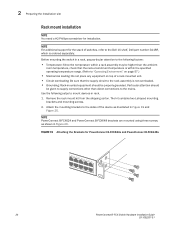
... for PowerConnect B-FCX624s and PowerConnect B-FCX648s 20 PowerConnect B-FCX Switch Hardware Installation Guide 53-1002267-01 Before mounting the switch in a rack, pay particular attention to the following setps to mount devices in rack. 1. Use the following factors: • Temperature: Since the temperature within a rack assembly may be higher than direct connections to the Dell 1U shelf, Dell part number-G118R, which is within the specified operating temperature range. (Refer to...
... for PowerConnect B-FCX624s and PowerConnect B-FCX648s 20 PowerConnect B-FCX Switch Hardware Installation Guide 53-1002267-01 Before mounting the switch in a rack, pay particular attention to the following setps to mount devices in rack. 1. Use the following factors: • Temperature: Since the temperature within a rack assembly may be higher than direct connections to the Dell 1U shelf, Dell part number-G118R, which is within the specified operating temperature range. (Refer to...

Hardware Installation Guide
Page 35
.... PowerConnect B-FCX Switch Hardware Installation Guide 25 53-1002267-01 The CLI is a text-based interface that can access the system through cable. Attaching a PC or terminal 2 NOTE To turn the system off, simply unplug the power cable or cables. NOTE The socket should be installed near the equipment and should be accessed through a direct serial connection to the serial port of the system using a straight-through Telnet, the Web management interface, or Brocade Network Advisor...
.... PowerConnect B-FCX Switch Hardware Installation Guide 25 53-1002267-01 The CLI is a text-based interface that can access the system through cable. Attaching a PC or terminal 2 NOTE To turn the system off, simply unplug the power cable or cables. NOTE The socket should be installed near the equipment and should be accessed through a direct serial connection to the serial port of the system using a straight-through Telnet, the Web management interface, or Brocade Network Advisor...
Hardware Installation Guide
Page 41
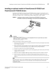
... install or replace a module. Before opening the module package, touch the bag to the switch casing to secure the module in "Port, system, and power status LEDs for PowerConnect B-FCX624 and PowerConnect B-FCX648" on these steps to power-down your device in a stack. For more information, see the PowerConnect B-FCX Series Configuration Guide PowerConnect B-FCX Switch Hardware Installation Guide 31 53-1002267-01 Installing an optional module in PowerConnect B-FCX624 and PowerConnect B-FCX648 devices 2 Installing an optional module in PowerConnect B-FCX624-E, PowerConnect B-FCX624...
... install or replace a module. Before opening the module package, touch the bag to the switch casing to secure the module in "Port, system, and power status LEDs for PowerConnect B-FCX624 and PowerConnect B-FCX648" on these steps to power-down your device in a stack. For more information, see the PowerConnect B-FCX Series Configuration Guide PowerConnect B-FCX Switch Hardware Installation Guide 31 53-1002267-01 Installing an optional module in PowerConnect B-FCX624 and PowerConnect B-FCX648 devices 2 Installing an optional module in PowerConnect B-FCX624-E, PowerConnect B-FCX624...

Hardware Installation Guide
Page 43
... a password using Brocade Network Advisor if an enable password for system administrators and is generally for a Super User has been configured on the flash module, save the system configuration to configure passwords. The level you enter when you configure the system IP address and configure switching and routing features. This level lets you first start a CLI session. To access the CONFIG mode, you can assign passwords using the Web Management Interface. At this level, you must set a super user password...
... a password using Brocade Network Advisor if an enable password for system administrators and is generally for a Super User has been configured on the flash module, save the system configuration to configure passwords. The level you enter when you configure the system IP address and configure switching and routing features. This level lets you first start a CLI session. To access the CONFIG mode, you can assign passwords using the Web Management Interface. At this level, you must set a super user password...

Hardware Installation Guide
Page 44
...lost password. 1. Enter no password at the prompt. After the console prompt reappears, assign a new password. 34 PowerConnect B-FCX Switch Hardware Installation Guide 53-1002267-01 At the opening CLI prompt, enter the following command to change to the device using the following command: PowerConnect# configure terminal PowerConnect(config)# 3. Syntax: enable super-user-password | read -only-password NOTE If you forget your super user password, refer to the serial port and a system reset. NOTE Recovery from a lost password By default, the CLI does not require passwords. Access...
...lost password. 1. Enter no password at the prompt. After the console prompt reappears, assign a new password. 34 PowerConnect B-FCX Switch Hardware Installation Guide 53-1002267-01 At the opening CLI prompt, enter the following command to change to the device using the following command: PowerConnect# configure terminal PowerConnect(config)# 3. Syntax: enable super-user-password | read -only-password NOTE If you forget your super user password, refer to the serial port and a system reset. NOTE Recovery from a lost password By default, the CLI does not require passwords. Access...

Hardware Installation Guide
Page 45
... Layer 2 software Use the following procedure to configure an IP Address on a configured system, enter the write memory command to the startup-config file. 3. PowerConnect> enable 2. PowerConnect(config)# ip address 192.22.3.44 255.255.255.0 5. Syntax: enable [] Syntax: configure terminal PowerConnect B-FCX Switch Hardware Installation Guide 35 53-1002267-01 By default, the CLI displays network masks in the mask immediately after the IP address. See the PowerConnect B-FCX Series Configuration Guide. You can manage the system using the serial connection to the CLI...
... Layer 2 software Use the following procedure to configure an IP Address on a configured system, enter the write memory command to the startup-config file. 3. PowerConnect> enable 2. PowerConnect(config)# ip address 192.22.3.44 255.255.255.0 5. Syntax: enable [] Syntax: configure terminal PowerConnect B-FCX Switch Hardware Installation Guide 35 53-1002267-01 By default, the CLI displays network masks in the mask immediately after the IP address. See the PowerConnect B-FCX Series Configuration Guide. You can manage the system using the serial connection to the CLI...

Hardware Installation Guide
Page 46
... erase the configuration on a configured system, enter the write memory command to save the running Layer 3 software Before attaching equipment to a Layer 3 Switch, you must use the serial connection to assign the first IP address. By default, you have already configured, the command erases the configuration. The following command: PowerConnect# configure terminalPrivileged EXEC Level PowerConnect(config)# Global CONFIG Level 4. PowerConnect> enable 2. Access the configuration level of the CLI by increasing the size of the subnet-per port by entering...
... erase the configuration on a configured system, enter the write memory command to save the running Layer 3 software Before attaching equipment to a Layer 3 Switch, you must use the serial connection to assign the first IP address. By default, you have already configured, the command erases the configuration. The following command: PowerConnect# configure terminalPrivileged EXEC Level PowerConnect(config)# Global CONFIG Level 4. PowerConnect> enable 2. Access the configuration level of the CLI by increasing the size of the subnet-per port by entering...

Hardware Installation Guide
Page 48
... this example create a Layer 3 protocol-based VLAN name "IP-Subnet_1.1.2.1/24" and add a range of virtual interfaces supported on the virtual interface to enable the Layer 3 switch to route protocol traffic from 1 to delete an IP address. To display the maximum number of the virtual-interface row. This section describes how to enter the subnet mask. 38 PowerConnect B-FCX Switch Hardware Installation Guide 53-1002267-01 PowerConnect(config-if-1/1/1)# no ip address 1.1.2.1 This command deletes IP address 1.1.2.1. 3 Configuring IP addresses...
... this example create a Layer 3 protocol-based VLAN name "IP-Subnet_1.1.2.1/24" and add a range of virtual interfaces supported on the virtual interface to enable the Layer 3 switch to route protocol traffic from 1 to delete an IP address. To display the maximum number of the virtual-interface row. This section describes how to enter the subnet mask. 38 PowerConnect B-FCX Switch Hardware Installation Guide 53-1002267-01 PowerConnect(config-if-1/1/1)# no ip address 1.1.2.1 This command deletes IP address 1.1.2.1. 3 Configuring IP addresses...

Hardware Installation Guide
Page 50
... Gbps Ethernet Copper ports on all 10/100 and Gigabit copper ports by default. Fiber cabling is required for stacking and non-stacking PowerConnect B-FCX models). To connect the device to another network device using a fiber optic transceiver, you will need fiber cabling with an LC connector. Refer to "Connecting a network device to a fiber port" on page 40. Connecting a network device to a fiber port For direct attachment from the device to a Gbps NIC, switch, or router, using a fiber port, you can disable auto...
... Gbps Ethernet Copper ports on all 10/100 and Gigabit copper ports by default. Fiber cabling is required for stacking and non-stacking PowerConnect B-FCX models). To connect the device to another network device using a fiber optic transceiver, you will need fiber cabling with an LC connector. Refer to "Connecting a network device to a fiber port" on page 40. Connecting a network device to a fiber port For direct attachment from the device to a Gbps NIC, switch, or router, using a fiber port, you can disable auto...
Hardware Installation Guide
Page 72
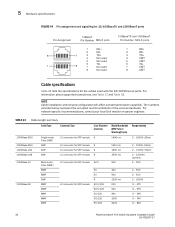
...-SX Single-mode Fiber (SMF) SMF SMF SMF Multi-mode Fiber (MMF) MMF MMF SMF MMF MMF MMF MMF MMF LC connector for SFP module 9 LC connector for SFP module 9 LC connector for SFP module 9 LC connector for SFP module 9 LC connector for SFP module 62.5 LC connector for the cables used with the 10/100 Ethernet ports. For information about supported transceivers, see Table 17 and Table 18. 5 Hardware specifications FIGURE 44...
...-SX Single-mode Fiber (SMF) SMF SMF SMF Multi-mode Fiber (MMF) MMF MMF SMF MMF MMF MMF MMF MMF LC connector for SFP module 9 LC connector for SFP module 9 LC connector for SFP module 9 LC connector for SFP module 9 LC connector for SFP module 62.5 LC connector for the cables used with the 10/100 Ethernet ports. For information about supported transceivers, see Table 17 and Table 18. 5 Hardware specifications FIGURE 44...

