Hardware Installation Guide
Page 3
...and danger notices viii Related publications viii Getting technical help or reporting errors ix Contacting Dell ix Chapter 1 Product Overview Hardware features 1 Control features 3 Power supplies 13 Chapter 2 Installing the PowerConnect B-FCX Switch Unpacking the device 15 Package contents 15 General requirements 15 Installation tasks ... map for serial cable 26 Installing and replacing a power supply unit 26 Installing or replacing fan trays on PowerConnect B-FCX624s and PowerConnect B-FCX648s devices 28 PowerConnect B-FCX Switch Hardware Installation Guide iii 53-1002267-01
...and danger notices viii Related publications viii Getting technical help or reporting errors ix Contacting Dell ix Chapter 1 Product Overview Hardware features 1 Control features 3 Power supplies 13 Chapter 2 Installing the PowerConnect B-FCX Switch Unpacking the device 15 Package contents 15 General requirements 15 Installation tasks ... map for serial cable 26 Installing and replacing a power supply unit 26 Installing or replacing fan trays on PowerConnect B-FCX624s and PowerConnect B-FCX648s devices 28 PowerConnect B-FCX Switch Hardware Installation Guide iii 53-1002267-01
Hardware Installation Guide
Page 4
Chapter 3 Chapter 4 Installing or replacing fan trays on PowerConnect B-FCX624 and PowerConnect B-FCX648 devices 28 Installing an optional module on PowerConnect B-FCX624s or PowerConnect B-FCX648s devices 30 Installing an optional module in PowerConnect B-FCX624 and PowerConnect B-FCX648 devices 31 Checking Network Devices and Testing Connectivity Assigning permanent passwords 33 Setting passwords 34 Recovering from a lost password 34 Configuring IP addresses...
Chapter 3 Chapter 4 Installing or replacing fan trays on PowerConnect B-FCX624 and PowerConnect B-FCX648 devices 28 Installing an optional module on PowerConnect B-FCX624s or PowerConnect B-FCX648s devices 30 Installing an optional module in PowerConnect B-FCX624 and PowerConnect B-FCX648 devices 31 Checking Network Devices and Testing Connectivity Assigning permanent passwords 33 Setting passwords 34 Recovering from a lost password 34 Configuring IP addresses...
Hardware Installation Guide
Page 7
...and software The following hardware platform is designed for system administrators with the following narrative-text formatting conventions are using a Dell Layer 3 Switch, you are used in this document. IP, RIP, OSPF, BGP, ISIS, IGMP, PIM, ...switching and routing. About This Document Audience This document is supported in this release: • PowerConnect B-FCX624s • PowerConnect B-FCX648s • PowerConnect B-FCX624 • PowerConnect B-FCX648 Document conventions This section describes text formatting conventions and important notice formats used in this guide.
...and software The following hardware platform is designed for system administrators with the following narrative-text formatting conventions are using a Dell Layer 3 Switch, you are used in this document. IP, RIP, OSPF, BGP, ISIS, IGMP, PIM, ...switching and routing. About This Document Audience This document is supported in this release: • PowerConnect B-FCX624s • PowerConnect B-FCX648s • PowerConnect B-FCX624 • PowerConnect B-FCX648 Document conventions This section describes text formatting conventions and important notice formats used in this guide.

Hardware Installation Guide
Page 11
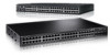
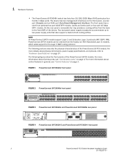
...rear-panel power supply receptacles allow stacking for up to two power supply units that also support a back-to -back cooling airflow. • The PowerConnect B-FCX624-I switch has twenty four 10/100/1000 Mbps RJ45 ports plus four Combo 1 Gbps ports. The front panel also has a module slot for up ...Gbps SFP+ module. Two rear-panel power supply receptacles allow stacking for an optional two-port 10 Gbps Ethernet XFP module. • The PowerConnect B-FCX624-E switch has twenty four 10/100/1000 Mbps RJ45 ports plus four Combo ports, which include four 10/100/1000 Mbps RJ45 ports and ...
...rear-panel power supply receptacles allow stacking for up to two power supply units that also support a back-to -back cooling airflow. • The PowerConnect B-FCX624-I switch has twenty four 10/100/1000 Mbps RJ45 ports plus four Combo 1 Gbps ports. The front panel also has a module slot for up ...Gbps SFP+ module. Two rear-panel power supply receptacles allow stacking for an optional two-port 10 Gbps Ethernet XFP module. • The PowerConnect B-FCX624-E switch has twenty four 10/100/1000 Mbps RJ45 ports plus four Combo ports, which include four 10/100/1000 Mbps RJ45 ports and ...
Hardware Installation Guide
Page 12
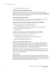
... a slot for the Layer 3 BGP routing protocol. The following figures show the front panels of -band Management Interface). FIGURE 1 PowerConnect B-FCX624s front panel Slot 3 A/S FIGURE 2 PowerConnect B-FCX648s front panel A/S FIGURE 3 PowerConnect B-FCX624s and PowerConnect B-FCX648s rear panel FIGURE 4 PowerConnect B-FCX624-E and PowerConnect B-FCX624-I switch has forty four 10/100/1000 Mbps RJ45 ports plus four Combo 1 Gbps ports. NOTE All...
... a slot for the Layer 3 BGP routing protocol. The following figures show the front panels of -band Management Interface). FIGURE 1 PowerConnect B-FCX624s front panel Slot 3 A/S FIGURE 2 PowerConnect B-FCX648s front panel A/S FIGURE 3 PowerConnect B-FCX624s and PowerConnect B-FCX648s rear panel FIGURE 4 PowerConnect B-FCX624-E and PowerConnect B-FCX624-I switch has forty four 10/100/1000 Mbps RJ45 ports plus four Combo 1 Gbps ports. NOTE All...

Hardware Installation Guide
Page 13
... 2 4 6 8 10 12 14 16 18 20 22 24 26 28 30 32 34 36 38 40 42 44 46 48 FIGURE 6 PowerConnect B-FCX624-E, PowerConnect B-FCX624-I, PowerConnect B-FCX648-E , PowerConnect B-FCX648-I rear panels CAUTION For the PowerConnect B-FCX624-E, PowerConnect B-FCX624-I, PowerConnect B-FCX648-E , and PowerConnect B-FCX648-I " as shown in Table 1. The power supplies and fan trays are clearly labeled with either a green arrow with an...
... 2 4 6 8 10 12 14 16 18 20 22 24 26 28 30 32 34 36 38 40 42 44 46 48 FIGURE 6 PowerConnect B-FCX624-E, PowerConnect B-FCX624-I, PowerConnect B-FCX648-E , PowerConnect B-FCX648-I rear panels CAUTION For the PowerConnect B-FCX624-E, PowerConnect B-FCX624-I, PowerConnect B-FCX648-E , and PowerConnect B-FCX648-I " as shown in Table 1. The power supplies and fan trays are clearly labeled with either a green arrow with an...
Hardware Installation Guide
Page 14
... ports (ports 1~4). 1 Hardware features • Out-of the port can be configured manually. Network interfaces for PowerConnect B-FCX624s and PowerConnect B-FCX648s PowerConnect B-FCX devices contain the following interfaces: • 10/100/1000 Mbps ports with RJ45 copper connectors • ...-compliant fiber transceivers • Optional 2-port 10Gbps Ethernet XFP module • CX4 stacking ports Network interfaces for PowerConnect B-FCX624 and PowerConnect B-FCX648 PowerConnect B-FCX devices contain the following interfaces: • 10/100/1000 ports with RJ45 copper connectors • 100...
... ports (ports 1~4). 1 Hardware features • Out-of the port can be configured manually. Network interfaces for PowerConnect B-FCX624s and PowerConnect B-FCX648s PowerConnect B-FCX devices contain the following interfaces: • 10/100/1000 Mbps ports with RJ45 copper connectors • ...-compliant fiber transceivers • Optional 2-port 10Gbps Ethernet XFP module • CX4 stacking ports Network interfaces for PowerConnect B-FCX624 and PowerConnect B-FCX648 PowerConnect B-FCX devices contain the following interfaces: • 10/100/1000 ports with RJ45 copper connectors • 100...
Hardware Installation Guide
Page 15
... N/A B-FCX648 4-port 1 Gbps SFP module (optional) devices with combined with SFP ports. module Optional four-port 1 Gbps SFP module PowerConnect B-FCX624 devices with optional four-port 10 Gbps SFP+ module 24 10/100/1000 Mbps RJ45 ports 4-port 10 Gbps SFP+ N/A module (optional...ports (acting as a 1 Gbps SFP Combo port). You must install the optional SFP or SFP+ module for PowerConnect B-FCX models. Hardware features 1 NOTE PowerConnect B-FCX624 and PowerConnect B-FCX648 devices do not ship with the first four 10/100/1000 optional four-port Mbps RJ45 copper ports (acting...
... N/A B-FCX648 4-port 1 Gbps SFP module (optional) devices with combined with SFP ports. module Optional four-port 1 Gbps SFP module PowerConnect B-FCX624 devices with optional four-port 10 Gbps SFP+ module 24 10/100/1000 Mbps RJ45 ports 4-port 10 Gbps SFP+ N/A module (optional...ports (acting as a 1 Gbps SFP Combo port). You must install the optional SFP or SFP+ module for PowerConnect B-FCX models. Hardware features 1 NOTE PowerConnect B-FCX624 and PowerConnect B-FCX648 devices do not ship with the first four 10/100/1000 optional four-port Mbps RJ45 copper ports (acting...

Hardware Installation Guide
Page 16
...SMF with LC connector, Optical Monitoring Capable. Optional two-port 10 Gbps XFP uplink module The PowerConnect B-FCX624s and PowerConnect B-FCX648s devices include a slot on PowerConnect B-FCX devices. TABLE 3 Interface SFP network interfaces Show Media Description Description 1000Base-BX-D 1000Base-...FX M-FX_IR M-FX-LR 1000Base-BXD SFP optic SMF, transmits at 1490nm and receives at 10 Gbps full duplex mode. 6 PowerConnect B-FCX Switch Hardware Installation Guide 53-1002267-01 1 Hardware features SFP interfaces Table 3 describes the network interfaces supported on the...
...SMF with LC connector, Optical Monitoring Capable. Optional two-port 10 Gbps XFP uplink module The PowerConnect B-FCX624s and PowerConnect B-FCX648s devices include a slot on PowerConnect B-FCX devices. TABLE 3 Interface SFP network interfaces Show Media Description Description 1000Base-BX-D 1000Base-...FX M-FX_IR M-FX-LR 1000Base-BXD SFP optic SMF, transmits at 1490nm and receives at 10 Gbps full duplex mode. 6 PowerConnect B-FCX Switch Hardware Installation Guide 53-1002267-01 1 Hardware features SFP interfaces Table 3 describes the network interfaces supported on the...

Hardware Installation Guide
Page 17
...+ module, and connecting devices using standard duplex LC cables. Hardware features 1 CAUTION The optional 10Gbps XFP module is down . PowerConnect B-FCX624 and PowerConnect B-FCX648 devices can be combined in an IronStack topology, see the PowerConnect B-FCX Series Configuration Guide. FIGURE 8 Four-port 1 Gbps SFP module FCX-4G 1F 2F 3F 4F TABLE 5 LED Four...
...+ module, and connecting devices using standard duplex LC cables. Hardware features 1 CAUTION The optional 10Gbps XFP module is down . PowerConnect B-FCX624 and PowerConnect B-FCX648 devices can be combined in an IronStack topology, see the PowerConnect B-FCX Series Configuration Guide. FIGURE 8 Four-port 1 Gbps SFP module FCX-4G 1F 2F 3F 4F TABLE 5 LED Four...

Hardware Installation Guide
Page 18
... can be configured on these two ports in length • Requires latch-style receptacle or SFF-8470 plug NOTE PowerConnect B-FCX624-E, PowerConnect B-FCX624-I, PowerConnect B-FCX648-E, and PowerConnect B-FCX648-I devices can perform data transmission directly through copper links of up to 3 meters. 1 Hardware features FIGURE... to 3 meters in order for them to pass regular traffic. 16/10 Gbps Ethernet CX4 stacking ports The PowerConnect B-FCX624s and PowerConnect B-FCX648s devices include two 16/10 Gbps Ethernet CX4 ports on the rear panel (the stacking ports). Cable specifications...
... can be configured on these two ports in length • Requires latch-style receptacle or SFF-8470 plug NOTE PowerConnect B-FCX624-E, PowerConnect B-FCX624-I, PowerConnect B-FCX648-E, and PowerConnect B-FCX648-I devices can perform data transmission directly through copper links of up to 3 meters. 1 Hardware features FIGURE... to 3 meters in order for them to pass regular traffic. 16/10 Gbps Ethernet CX4 stacking ports The PowerConnect B-FCX624s and PowerConnect B-FCX648s devices include two 16/10 Gbps Ethernet CX4 ports on the rear panel (the stacking ports). Cable specifications...

Hardware Installation Guide
Page 21
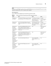
... Off Off Running Yes Running No Failure No Running No Failure No Power Off or No Failure Port, system, and power status LEDs for PowerConnect B-FCX624 and PowerConnect B-FCX648 PowerConnect B-FCX switches include a display panel for the device to function normally. Hardware features 1 NOTE Both "AC OK" and "DC OK" LEDs must be green... PSU with a remote port. The LEDs, which are located on the front panel for easy viewing, are shown below and described in the following tables. PowerConnect B-FCX Switch Hardware Installation Guide 11 53-1002267-01
... Off Off Running Yes Running No Failure No Running No Failure No Power Off or No Failure Port, system, and power status LEDs for PowerConnect B-FCX624 and PowerConnect B-FCX648 PowerConnect B-FCX switches include a display panel for the device to function normally. Hardware features 1 NOTE Both "AC OK" and "DC OK" LEDs must be green... PSU with a remote port. The LEDs, which are located on the front panel for easy viewing, are shown below and described in the following tables. PowerConnect B-FCX Switch Hardware Installation Guide 11 53-1002267-01

Hardware Installation Guide
Page 23
... Hardware Installation Guide 13 53-1002267-01 TABLE 14 State Switch status for the device to function normally. PowerConnect B-FCX624s, PowerConnect B-FCX648s, PowerConnect B-FCX624, and PowerConnect B-FCX648 devices use a 210W PSU. Each device ships with both 'AC OK' 'DC OK' LEDs Off AC OK DC OK 'DC OK' LEDs Red AC ...
... Hardware Installation Guide 13 53-1002267-01 TABLE 14 State Switch status for the device to function normally. PowerConnect B-FCX624s, PowerConnect B-FCX648s, PowerConnect B-FCX624, and PowerConnect B-FCX648 devices use a 210W PSU. Each device ships with both 'AC OK' 'DC OK' LEDs Off AC OK DC OK 'DC OK' LEDs Red AC ...
Hardware Installation Guide
Page 24
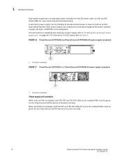
...be installed to provide backup power in case of the installed PSUs must be green for the PowerConnect B-FCX device to function normally. 14 PowerConnect B-FCX Switch Hardware Installation Guide 53-1002267-01 For information on LED status refer to "...For instructions on installing and replacing a power supply refer to Table 9. FIGURE 16 PowerConnect B-FCX624s and PowerConnect B-FCX648s AC power supply receptacle 1 1 AC power receptacle FIGURE 17 PowerConnect B-FCX624 and PowerConnect B-FCX648 AC power supply receptacle 1 1 AC power receptacle Power supply unit operation When...
...be installed to provide backup power in case of the installed PSUs must be green for the PowerConnect B-FCX device to function normally. 14 PowerConnect B-FCX Switch Hardware Installation Guide 53-1002267-01 For information on LED status refer to "...For instructions on installing and replacing a power supply refer to Table 9. FIGURE 16 PowerConnect B-FCX624s and PowerConnect B-FCX648s AC power supply receptacle 1 1 AC power receptacle FIGURE 17 PowerConnect B-FCX624 and PowerConnect B-FCX648 AC power supply receptacle 1 1 AC power receptacle Power supply unit operation When...
Hardware Installation Guide
Page 30
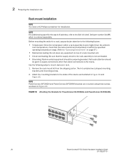
..., Dell part number-G118R, which is not overloaded. • Grounding: Rack-mounted equipment should be properly grounded. The kit contains two L-shaped mounting brackets and mounting screws. 2. Remove the rack mount kit from the shipping carton. 2 Preparing the installation site Rack mount installation NOTE You need a #2 Phillips screwdriver for PowerConnect B-FCX624s and PowerConnect B-FCX648s...
..., Dell part number-G118R, which is not overloaded. • Grounding: Rack-mounted equipment should be properly grounded. The kit contains two L-shaped mounting brackets and mounting screws. 2. Remove the rack mount kit from the shipping carton. 2 Preparing the installation site Rack mount installation NOTE You need a #2 Phillips screwdriver for PowerConnect B-FCX624s and PowerConnect B-FCX648s...
Hardware Installation Guide
Page 31
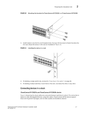
...21 53-1002267-01 Connecting devices in a stack PowerConnect B-FCX624s and PowerConnect B-FCX648s devices Figure 5 shows how the stack cables are connected between switches in a rack 4. Install retainer nuts into the rack. PowerConnect B-FCX devices support linear and ring stack topologies,..., proceed to fasten brackets into the non-threaded holes. Preparing the installation site 2 FIGURE 20 Attaching the brackets for PowerConnect B-FCX624 and PowerConnect B-FCX648 3. Attach the device in the rack as standalone devices. If installing multiple switches, mount them in the rack...
...21 53-1002267-01 Connecting devices in a stack PowerConnect B-FCX624s and PowerConnect B-FCX648s devices Figure 5 shows how the stack cables are connected between switches in a rack 4. Install retainer nuts into the rack. PowerConnect B-FCX devices support linear and ring stack topologies,..., proceed to fasten brackets into the non-threaded holes. Preparing the installation site 2 FIGURE 20 Attaching the brackets for PowerConnect B-FCX624 and PowerConnect B-FCX648 3. Attach the device in the rack as standalone devices. If installing multiple switches, mount them in the rack...
Hardware Installation Guide
Page 33
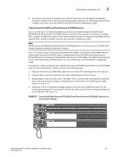
... MM Fiber cable into the remaining stacking port on the bottom unit and the other PowerConnect B-FCX device. Using PowerConnect B-FCX624 and PowerConnect B-FCX648 devices in the stack will operate as Standby Controller, with the rest of ...). For more information, see the PowerConnect B-FCX Series Configuration Guide. PowerConnect B-FCX624 and PowerConnect B-FCX648 devices Figure 23 and Figure 24 show how stacking cables are connected between PowerConnect B-FCX624 and PowerConnect B-FCX648 devices in a stack. NOTE PowerConnect B-FCX624 and PowerConnect B-FCX648 devices must have a 4-...
... MM Fiber cable into the remaining stacking port on the bottom unit and the other PowerConnect B-FCX device. Using PowerConnect B-FCX624 and PowerConnect B-FCX648 devices in the stack will operate as Standby Controller, with the rest of ...). For more information, see the PowerConnect B-FCX Series Configuration Guide. PowerConnect B-FCX624 and PowerConnect B-FCX648 devices Figure 23 and Figure 24 show how stacking cables are connected between PowerConnect B-FCX624 and PowerConnect B-FCX648 devices in a stack. NOTE PowerConnect B-FCX624 and PowerConnect B-FCX648 devices must have a 4-...
Hardware Installation Guide
Page 34
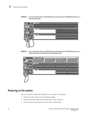
...Insert the power cable plug into a 115V, 120V, or 240V outlet. 24 PowerConnect B-FCX Switch Hardware Installation Guide 53-1002267-01 2 Powering on the system FIGURE 24 Connecting PowerConnect B-FCX624-E and PowerConnect B-FCX648-E devices in a ring stack topology Reset 1 Console PS 2 Diag Mgmt...13 15 17 19 21 23 2 4 6 8 10 12 14 16 18 20 22 24 FIGURE 25 Connecting PowerConnect B-FCX624-E and PowerConnect B-FCX648-E devices in a mixed stack with an PowerConnect B-FCX624s device FastIron FCX648S Reset 1 Console PS 2 Diag Mgmt 1 3 5 7 9 11 13 15 17 19 ...
...Insert the power cable plug into a 115V, 120V, or 240V outlet. 24 PowerConnect B-FCX Switch Hardware Installation Guide 53-1002267-01 2 Powering on the system FIGURE 24 Connecting PowerConnect B-FCX624-E and PowerConnect B-FCX648-E devices in a ring stack topology Reset 1 Console PS 2 Diag Mgmt...13 15 17 19 21 23 2 4 6 8 10 12 14 16 18 20 22 24 FIGURE 25 Connecting PowerConnect B-FCX624-E and PowerConnect B-FCX648-E devices in a mixed stack with an PowerConnect B-FCX624s device FastIron FCX648S Reset 1 Console PS 2 Diag Mgmt 1 3 5 7 9 11 13 15 17 19 ...
Hardware Installation Guide
Page 36
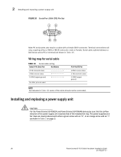
Serial cable options between a Dell device and a PC or terminal are used. Installing and replacing a power supply unit CAUTION For the PowerConnect B-FCX624 and PowerConnect B-FCX648 devices,be connected. Wiring map for serial cable TABLE 16 Serial cable wiring Switch 9-Pin Serial Port Null Modem 2 TXD ... DTE) Pin-Out 1 5 69 Most PC serial ports also require a cable with an "I" as shown in Table 1 on page 3. 26 PowerConnect B-FCX Switch Hardware Installation Guide 53-1002267-01 The power supplies and fan trays are clearly labeled with either a DB-9 or DB-25 connector, ...
Serial cable options between a Dell device and a PC or terminal are used. Installing and replacing a power supply unit CAUTION For the PowerConnect B-FCX624 and PowerConnect B-FCX648 devices,be connected. Wiring map for serial cable TABLE 16 Serial cable wiring Switch 9-Pin Serial Port Null Modem 2 TXD ... DTE) Pin-Out 1 5 69 Most PC serial ports also require a cable with an "I" as shown in Table 1 on page 3. 26 PowerConnect B-FCX Switch Hardware Installation Guide 53-1002267-01 The power supplies and fan trays are clearly labeled with either a DB-9 or DB-25 connector, ...

Hardware Installation Guide
Page 38
... or replacing fan trays on PowerConnect B-FCX624s and PowerConnect B-FCX648s devices Installing or replacing fan trays on PowerConnect B-FCX624s and PowerConnect B-FCX648s devices FIGURE 28 Installing a fan tray on PowerConnect B-FCX624 and PowerConnect B-FCX648 devices CAUTION For PowerConnect B-FCX624 and PowerConnect B-FCX648 devices, be sure that...the installed fan tray from the anti-static shielded bag. 4. Installing or replacing fan trays on a PowerConnect B-FCX624s or PowerConnect B-FCX648s device Perform the following steps to secure the fan tray in the switch. 1. Remove the...
... or replacing fan trays on PowerConnect B-FCX624s and PowerConnect B-FCX648s devices Installing or replacing fan trays on PowerConnect B-FCX624s and PowerConnect B-FCX648s devices FIGURE 28 Installing a fan tray on PowerConnect B-FCX624 and PowerConnect B-FCX648 devices CAUTION For PowerConnect B-FCX624 and PowerConnect B-FCX648 devices, be sure that...the installed fan tray from the anti-static shielded bag. 4. Installing or replacing fan trays on a PowerConnect B-FCX624s or PowerConnect B-FCX648s device Perform the following steps to secure the fan tray in the switch. 1. Remove the...


