Hardware Installation Guide
Page 3
... errors ix Contacting Dell ix Chapter 1 Product Overview Hardware features 1 Control features 3 Power supplies 13 Chapter 2 Installing the PowerConnect B-FCX Switch Unpacking the device 15 Package contents 15 General requirements 15 Installation tasks 16 Installation precautions 16 General precautions 17 Lifting precautions 17 Power precautions 17 Preparing the installation site 18 Cabling infrastructure 18 Installation location 18 Installing the device 19 Desktop installation 19 Rack mount installation 20 Connecting devices in a stack...
... errors ix Contacting Dell ix Chapter 1 Product Overview Hardware features 1 Control features 3 Power supplies 13 Chapter 2 Installing the PowerConnect B-FCX Switch Unpacking the device 15 Package contents 15 General requirements 15 Installation tasks 16 Installation precautions 16 General precautions 17 Lifting precautions 17 Power precautions 17 Preparing the installation site 18 Cabling infrastructure 18 Installation location 18 Installing the device 19 Desktop installation 19 Rack mount installation 20 Connecting devices in a stack...
Hardware Installation Guide
Page 4
... a lost password 34 Configuring IP addresses 35 Devices running Layer 2 software 35 Devices running Layer 3 software 36 Connecting network devices 39 Connectors 39 Cable specifications 39 Connecting to Ethernet or fast Ethernet hubs 39 Connecting to workstations, servers, or routers 40 Connecting a network device to a fiber port 40 Testing connectivity 43 Pinging an IP address 43 Observing LEDs 43 Tracing a route 45 Troubleshooting network connections 45 Using Virtual Cable Testing to diagnose a cable 46 Digital optical monitoring 47 Managing the PowerConnect B-FCX Hardware...
... a lost password 34 Configuring IP addresses 35 Devices running Layer 2 software 35 Devices running Layer 3 software 36 Connecting network devices 39 Connectors 39 Cable specifications 39 Connecting to Ethernet or fast Ethernet hubs 39 Connecting to workstations, servers, or routers 40 Connecting a network device to a fiber port 40 Testing connectivity 43 Pinging an IP address 43 Observing LEDs 43 Tracing a route 45 Troubleshooting network connections 45 Using Virtual Cable Testing to diagnose a cable 46 Digital optical monitoring 47 Managing the PowerConnect B-FCX Hardware...
Hardware Installation Guide
Page 8
..., and danger statements are presented in bold: for example, show version. Variables are also attached directly to products to hardware, firmware, software, or data. NOTE A note provides a tip, guidance or advice, emphasizes important information, or provides a reference to the command syntax in this guide: • PowerConnect B-FCX Series Configuration Guide - Otherwise, this guide are used in this manual. Optional parameter. CAUTION A Caution statement alerts you to...
..., and danger statements are presented in bold: for example, show version. Variables are also attached directly to products to hardware, firmware, software, or data. NOTE A note provides a tip, guidance or advice, emphasizes important information, or provides a reference to the command syntax in this guide: • PowerConnect B-FCX Series Configuration Guide - Otherwise, this guide are used in this manual. Optional parameter. CAUTION A Caution statement alerts you to...
Hardware Installation Guide
Page 9
.... Click your investment in the manuals, contact Dell Technical Support. PowerConnect B-FCX Switch Hardware Installation Guide ix 53-1002267-01 Getting technical help or reporting errors Dell is convenient for sales, technical support, or customer service issues: 1. Dell provides several online and telephone-based support and service options. Visit http://support.dell.com. 2. Choose the method of contacting Dell that is committed to Product Manuals at the bottom of the...
.... Click your investment in the manuals, contact Dell Technical Support. PowerConnect B-FCX Switch Hardware Installation Guide ix 53-1002267-01 Getting technical help or reporting errors Dell is convenient for sales, technical support, or customer service issues: 1. Dell provides several online and telephone-based support and service options. Visit http://support.dell.com. 2. Choose the method of contacting Dell that is committed to Product Manuals at the bottom of the...

Hardware Installation Guide
Page 13
... E POWER SUPPLY/FAN FRU TYPES MUST BE THE SAME AIRFLOW E AIRFLOW PowerConnect B-FCX624-I and PowerConnect B-FCX648-I " as shown in Table 1. The power supplies and fan trays are clearly labeled with either a green arrow with an "E", or an orange arrow with an "I WARNING POWER SUPPLY/FAN FRU TYPES MUST BE THE SAME AIRFLOW AIRFLOW Control features Each device front panel includes the following control features: • Serial management interface (the DB9 port labeled Console) PowerConnect B-FCX Switch Hardware Installation Guide...
... E POWER SUPPLY/FAN FRU TYPES MUST BE THE SAME AIRFLOW E AIRFLOW PowerConnect B-FCX624-I and PowerConnect B-FCX648-I " as shown in Table 1. The power supplies and fan trays are clearly labeled with either a green arrow with an "E", or an orange arrow with an "I WARNING POWER SUPPLY/FAN FRU TYPES MUST BE THE SAME AIRFLOW AIRFLOW Control features Each device front panel includes the following control features: • Serial management interface (the DB9 port labeled Console) PowerConnect B-FCX Switch Hardware Installation Guide...
Hardware Installation Guide
Page 14
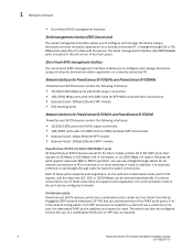
...; Optional 2-port 10Gbps Ethernet XFP module • CX4 stacking ports Network interfaces for PowerConnect B-FCX624 and PowerConnect B-FCX648 PowerConnect B-FCX devices contain the following interfaces: • 10/100/1000 ports with RJ45 copper connectors • 100/1000 ports with the device. In addition, it is installed in the left corner of these ports does not support auto-negotiation, the communication mode of the port can use straight-through cable for the fiber models contain...
...; Optional 2-port 10Gbps Ethernet XFP module • CX4 stacking ports Network interfaces for PowerConnect B-FCX624 and PowerConnect B-FCX648 PowerConnect B-FCX devices contain the following interfaces: • 10/100/1000 ports with RJ45 copper connectors • 100/1000 ports with the device. In addition, it is installed in the left corner of these ports does not support auto-negotiation, the communication mode of the port can use straight-through cable for the fiber models contain...

Hardware Installation Guide
Page 18
... connection exists, or the link is down . Cable specifications for CX4 stacking ports The following tables. 8 PowerConnect B-FCX Switch Hardware Installation Guide 53-1002267-01 The Up Link and Down Link LEDs on the front panel indicate operational status. Activity) Off The link is down . 1 Hardware features FIGURE 9 Four-port 10 Gbps SFP+ module FCX-4XG X1 X2 X3 X4 TABLE 6 LED Four-port 10 Gbps SFP+ module status LEDs Condition Status Link or Act LED (Link or On or flashing Green Port has a valid link...
... connection exists, or the link is down . Cable specifications for CX4 stacking ports The following tables. 8 PowerConnect B-FCX Switch Hardware Installation Guide 53-1002267-01 The Up Link and Down Link LEDs on the front panel indicate operational status. Activity) Off The link is down . 1 Hardware features FIGURE 9 Four-port 10 Gbps SFP+ module FCX-4XG X1 X2 X3 X4 TABLE 6 LED Four-port 10 Gbps SFP+ module status LEDs Condition Status Link or Act LED (Link or On or flashing Green Port has a valid link...

Hardware Installation Guide
Page 21
... No Failure Port, system, and power status LEDs for PowerConnect B-FCX624 and PowerConnect B-FCX648 PowerConnect B-FCX switches include a display panel for key system and port indicators that simplifies installation and network troubleshooting. PowerConnect B-FCX Switch Hardware Installation Guide 11 53-1002267-01 Hardware features 1 NOTE Both "AC OK" and "DC OK" LEDs must be green for easy viewing, are located on the front panel for the device to function normally. FIGURE 13 Port status LEDs 1 Reset 1 Console PS...
... No Failure Port, system, and power status LEDs for PowerConnect B-FCX624 and PowerConnect B-FCX648 PowerConnect B-FCX switches include a display panel for key system and port indicators that simplifies installation and network troubleshooting. PowerConnect B-FCX Switch Hardware Installation Guide 11 53-1002267-01 Hardware features 1 NOTE Both "AC OK" and "DC OK" LEDs must be green for easy viewing, are located on the front panel for the device to function normally. FIGURE 13 Port status LEDs 1 Reset 1 Console PS...

Hardware Installation Guide
Page 25
... system. PowerConnect B-FCX Switch Hardware Installation Guide 15 53-1002267-01 Verify the contents of purchase. This information is required to the Console serial port on the switch. C14) (for qualified service personnel. CAUTION Before beginning the installation, see the pinout information in "Power precautions" on page 25. Unpacking the device PowerConnect B-FCX devices ship with a .5M CX-4 stacking cable • Rack mount kit • Document Kit •...
... system. PowerConnect B-FCX Switch Hardware Installation Guide 15 53-1002267-01 Verify the contents of purchase. This information is required to the Console serial port on the switch. C14) (for qualified service personnel. CAUTION Before beginning the installation, see the pinout information in "Power precautions" on page 25. Unpacking the device PowerConnect B-FCX devices ship with a .5M CX-4 stacking cable • Rack mount kit • Document Kit •...

Hardware Installation Guide
Page 26
... using the Web management interface. 8 Once you power on page 19 (use Brocade Guide Network Advisor to manage the device. 11 Secure access to configure the device through the Command Line Interface (CLI). 6 No default password is performed using the CLI or the Web PowerConnect B-FCX Series Configuration management interface. You also can be located. "Powering on the system" on page 24 3 Install the Dell device on a desktop, in this manual. 5 Attach a terminal or PC to accept network equipment. Subsequent IP address configuration...
... using the Web management interface. 8 Once you power on page 19 (use Brocade Guide Network Advisor to manage the device. 11 Secure access to configure the device through the Command Line Interface (CLI). 6 No default password is performed using the CLI or the Web PowerConnect B-FCX Series Configuration management interface. You also can be located. "Powering on the system" on page 24 3 Install the Dell device on a desktop, in this manual. 5 Attach a terminal or PC to accept network equipment. Subsequent IP address configuration...
Hardware Installation Guide
Page 30
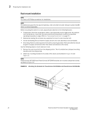
... top of a rack-mounted unit. • Circuit overloading: Be sure that the supply circuit to the mains. 2 Preparing the installation site Rack mount installation NOTE You need a #2 Phillips screwdriver for PowerConnect B-FCX624s and PowerConnect B-FCX648s 20 PowerConnect B-FCX Switch Hardware Installation Guide 53-1002267-01 Attach the mounting brackets to the sides of switches, refer to the Dell 1U shelf, Dell part number-G118R, which is not overloaded. • Grounding: Rack-mounted equipment should...
... top of a rack-mounted unit. • Circuit overloading: Be sure that the supply circuit to the mains. 2 Preparing the installation site Rack mount installation NOTE You need a #2 Phillips screwdriver for PowerConnect B-FCX624s and PowerConnect B-FCX648s 20 PowerConnect B-FCX Switch Hardware Installation Guide 53-1002267-01 Attach the mounting brackets to the sides of switches, refer to the Dell 1U shelf, Dell part number-G118R, which is not overloaded. • Grounding: Rack-mounted equipment should...

Hardware Installation Guide
Page 35
... device and through cable. Attaching a PC or terminal 2 NOTE To turn the system off, simply unplug the power cable or cables. After you assign an IP address, you must have access to the serial port of the system using a straight-through Telnet connections. Connect a PC or terminal to the Command Line Interface (CLI). See Figure 26. Dell devices come with a standard male DB-9 connector, shown in the PowerConnect B-FCX Series Configuration Guide. NOTE If...
... device and through cable. Attaching a PC or terminal 2 NOTE To turn the system off, simply unplug the power cable or cables. After you assign an IP address, you must have access to the serial port of the system using a straight-through Telnet connections. Connect a PC or terminal to the Command Line Interface (CLI). See Figure 26. Dell devices come with a standard male DB-9 connector, shown in the PowerConnect B-FCX Series Configuration Guide. NOTE If...
Hardware Installation Guide
Page 41
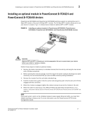
... power status LEDs for PowerConnect B-FCX624 and PowerConnect B-FCX648" on the 10 Gbps module to pass regular Ethernet traffic, you install or replace a module. FIGURE 31 Installing an optional module in PowerConnect B-FCX624 and PowerConnect B-FCX648 devices PowerConnect B-FCX624 and PowerConnect B-FCX648 switches support an optional four-port 1 Gbps SFP module or four-port 10 Gbps SFP+ module. Remove the module from the slot by removing the two screws with the connector. 5. For more information, see the PowerConnect B-FCX Series Configuration Guide PowerConnect B-FCX Switch Hardware...
... power status LEDs for PowerConnect B-FCX624 and PowerConnect B-FCX648" on the 10 Gbps module to pass regular Ethernet traffic, you install or replace a module. FIGURE 31 Installing an optional module in PowerConnect B-FCX624 and PowerConnect B-FCX648 devices PowerConnect B-FCX624 and PowerConnect B-FCX648 switches support an optional four-port 1 Gbps SFP module or four-port 10 Gbps SFP+ module. Remove the module from the slot by removing the two screws with the connector. 5. For more information, see the PowerConnect B-FCX Series Configuration Guide PowerConnect B-FCX Switch Hardware...

Hardware Installation Guide
Page 43
... as manage files on the device. To secure CLI access, Dell strongly recommends assigning passwords. The CLI contains the following levels of Enable passwords: • Super User - The configuration level. To access the CONFIG mode, you configure the system IP address and configure switching and routing features. This is generally for a Super User has been configured on the flash module, save the system configuration to the system. NOTE You cannot assign a password using Brocade Network Advisor if an enable password...
... as manage files on the device. To secure CLI access, Dell strongly recommends assigning passwords. The CLI contains the following levels of Enable passwords: • Super User - The configuration level. To access the CONFIG mode, you configure the system IP address and configure switching and routing features. This is generally for a Super User has been configured on the flash module, save the system configuration to the system. NOTE You cannot assign a password using Brocade Network Advisor if an enable password...

Hardware Installation Guide
Page 44
... enable super-user-password NOTE You must set the port configuration and read-only passwords: PowerConnect(config)# enable port-config-password PowerConnect(config)# enable read -only-password | port-config-password Passwords can regain super user access to the serial port and a system reset. Enter the following command to change to the Dell device. 2. NOTE Recovery from a lost password requires direct access to the device using the following commands to set the super user password before the initial system prompt appears, enter b to 32 characters long. Enter boot system flash...
... enable super-user-password NOTE You must set the port configuration and read-only passwords: PowerConnect(config)# enable port-config-password PowerConnect(config)# enable read -only-password | port-config-password Passwords can regain super user access to the serial port and a system reset. Enter the following command to change to the Dell device. 2. NOTE Recovery from a lost password requires direct access to the device using the following commands to set the super user password before the initial system prompt appears, enter b to 32 characters long. Enter boot system flash...

Hardware Installation Guide
Page 45
... running Layer 2 software. 1. See the PowerConnect B-FCX Series Configuration Guide. Devices running configuration to the startup-config file. 3. Syntax: enable [] Syntax: configure terminal PowerConnect B-FCX Switch Hardware Installation Guide 35 53-1002267-01 For example, enter "209.157.22.99/24" for the switch. By default, the CLI displays network masks in IP address format. You can manage the system using the serial connection to the CLI before you can change the display to the prefix format. Access the configuration level...
... running Layer 2 software. 1. See the PowerConnect B-FCX Series Configuration Guide. Devices running configuration to the startup-config file. 3. Syntax: enable [] Syntax: configure terminal PowerConnect B-FCX Switch Hardware Installation Guide 35 53-1002267-01 For example, enter "209.157.22.99/24" for the switch. By default, the CLI displays network masks in IP address format. You can manage the system using the serial connection to the CLI before you can change the display to the prefix format. Access the configuration level...

Hardware Installation Guide
Page 46
... IP subnet addresses per -interface table. At the opening CLI prompt, enter enable. PowerConnect> enable 2. This command erases the factory test configuration if still present: PowerConnect# erase startup-config CAUTION Use the erase startup-config command only for the interfaces on a configured system, enter the write memory command to save the running Layer 3 software Before attaching equipment to a Layer 3 Switch, you also can use the CLI through Telnet or the Web management interface. Configure the IP addresses and mask addresses for new...
... IP subnet addresses per -interface table. At the opening CLI prompt, enter enable. PowerConnect> enable 2. This command erases the factory test configuration if still present: PowerConnect# erase startup-config CAUTION Use the erase startup-config command only for the interfaces on a configured system, enter the write memory command to save the running Layer 3 software Before attaching equipment to a Layer 3 Switch, you also can use the CLI through Telnet or the Web management interface. Configure the IP addresses and mask addresses for new...

Hardware Installation Guide
Page 48
... Layer 3 switch to route protocol traffic from 1 to enter the subnet mask. 38 PowerConnect B-FCX Switch Hardware Installation Guide 53-1002267-01 The last two commands change to the interface configuration level for the virtual interface and assign an IP address to configure an IP address on a Layer 3 switch. To add a loopback interface, enter commands such as the MAC address for the VLAN. This section describes how to the interface. PowerConnect(config-if-1/1/1)# no ip address 1.1.2.1 This command deletes IP address 1.1.2.1. The router-interface command creates...
... Layer 3 switch to route protocol traffic from 1 to enter the subnet mask. 38 PowerConnect B-FCX Switch Hardware Installation Guide 53-1002267-01 The last two commands change to the interface configuration level for the virtual interface and assign an IP address to configure an IP address on a Layer 3 switch. To add a loopback interface, enter commands such as the MAC address for the VLAN. This section describes how to the interface. PowerConnect(config-if-1/1/1)# no ip address 1.1.2.1 This command deletes IP address 1.1.2.1. The router-interface command creates...

Hardware Installation Guide
Page 50
... Gigabit NICs or switches and routers through UTP cabling is required for stacking and non-stacking PowerConnect B-FCX models). Table 18 shows supported SFP and SFP+ transceivers. Fiber cabling is required for transceivers, see Table 24. 40 PowerConnect B-FCX Switch Hardware Installation Guide 53-1002267-01 This feature is enabled on the devices support automatic Media Dependent Interface (MDI) and Media Dependent Interface Crossover (MDIX) detection. For information about this feature and how configure it, refer...
... Gigabit NICs or switches and routers through UTP cabling is required for stacking and non-stacking PowerConnect B-FCX models). Table 18 shows supported SFP and SFP+ transceivers. Fiber cabling is required for transceivers, see Table 24. 40 PowerConnect B-FCX Switch Hardware Installation Guide 53-1002267-01 This feature is enabled on the devices support automatic Media Dependent Interface (MDI) and Media Dependent Interface Crossover (MDIX) detection. For information about this feature and how configure it, refer...
Hardware Installation Guide
Page 72
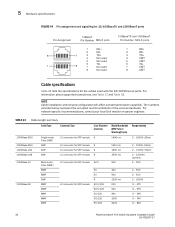
... Single-mode Fiber (SMF) SMF SMF SMF Multi-mode Fiber (MMF) MMF MMF SMF MMF MMF MMF MMF MMF LC connector for SFP module 9 LC connector for SFP module 9 LC connector for SFP module 9 LC connector for SFP module 9 LC connector for SFP module 62.5 LC connector for the cables used with the 10/100 Ethernet ports. The numbers provided below represent the accepted recommendations of the various standards. 5 Hardware specifications...
... Single-mode Fiber (SMF) SMF SMF SMF Multi-mode Fiber (MMF) MMF MMF SMF MMF MMF MMF MMF MMF LC connector for SFP module 9 LC connector for SFP module 9 LC connector for SFP module 9 LC connector for SFP module 9 LC connector for SFP module 62.5 LC connector for the cables used with the 10/100 Ethernet ports. The numbers provided below represent the accepted recommendations of the various standards. 5 Hardware specifications...

