
Command Line Interface (CLI) Guide (.htm)
Page 76
www.dell.com | support.dell.com Example The following example displays the login history of users. Console # show users login-history Login Time Jan 18 2005 23:58:17 Jan 19 2005 07:59:23 Jan 19 2005 08:23:48 Jan 19 2005 08:29:29 Jan 19 2005 08:42:31 Jan 19 2005 08:49:52 Username -------Robert Robert Bob Robert John Betty Protocol -------HTTP HTTP Serial HTTP SSH Telnet Location -------172.16.1.8 172.16.0.8 172.16.0.8 172.16.0.1 172.16.1.7 76 AAA Commands
www.dell.com | support.dell.com Example The following example displays the login history of users. Console # show users login-history Login Time Jan 18 2005 23:58:17 Jan 19 2005 07:59:23 Jan 19 2005 08:23:48 Jan 19 2005 08:29:29 Jan 19 2005 08:42:31 Jan 19 2005 08:49:52 Username -------Robert Robert Bob Robert John Betty Protocol -------HTTP HTTP Serial HTTP SSH Telnet Location -------172.16.1.8 172.16.0.8 172.16.0.8 172.16.0.1 172.16.1.7 76 AAA Commands
Command Line Interface (CLI) Guide (.htm)
Page 118
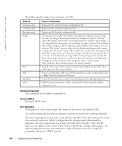
... no default configuration. Represents the backup configuration file. Boot file. The syntax for the file from network to network. www.dell.com | support.dell.com The following table displays keywords aliases to URL: Keyword running-config startup-config backup-config image boot tftp: xmodem: null...uploaded), the device ignores the user input sent to determine its size. Source for this behavior only applies to protocol and from a serial connection that manages the device. Command Mode Privileged EXEC mode User Guidelines The location of a file system dictates the format of which...
... no default configuration. Represents the backup configuration file. Boot file. The syntax for the file from network to network. www.dell.com | support.dell.com The following table displays keywords aliases to URL: Keyword running-config startup-config backup-config image boot tftp: xmodem: null...uploaded), the device ignores the user input sent to determine its size. Source for this behavior only applies to protocol and from a serial connection that manages the device. Command Mode Privileged EXEC mode User Guidelines The location of a file system dictates the format of which...

Command Line Interface (CLI) Guide (.htm)
Page 427
... asset tag as "1qwepot". System Management 427 Command Mode User EXEC mode User Guidelines There are no default configuration. Console# show users Username Protocol Bob Serial John SSH Robert HTTP Location --------- 172.16.0.1 172.16.0.8 show clock The show clock Default Configuration This command has no default configuration. Syntax show users...
... asset tag as "1qwepot". System Management 427 Command Mode User EXEC mode User Guidelines There are no default configuration. Console# show users Username Protocol Bob Serial John SSH Robert HTTP Location --------- 172.16.0.1 172.16.0.8 show clock The show clock Default Configuration This command has no default configuration. Syntax show users...

Command Line Interface (CLI) Guide (.htm)
Page 431
... of the device to be sent at each TTL level. (Range:1-10) • time_out - The default is 3 seconds. Console> show system id Service Tag: 89788978 Serial number: 8936589782 Asset tag: 7843678957 traceroute The traceroute user EXEC command discovers the IP routes that can be used. The device will normally pick the...
... of the device to be sent at each TTL level. (Range:1-10) • time_out - The default is 3 seconds. Console> show system id Service Tag: 89788978 Serial number: 8936589782 Asset tag: 7843678957 traceroute The traceroute user EXEC command discovers the IP routes that can be used. The device will normally pick the...
User's Guide (.htm)
Page 4
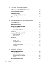
... Pinout Information Pin Connections for the 10/100/1000 Ethernet Interface 45 Pin Connections for SFP Interfaces 46 Serial Cable Connection 47 Connecting the Switch to a Terminal 48 AC Power Connection 49 4 Using Dell OpenManage Switch Administrator Starting the Application 51 Understanding the Interface 51 Using the Switch Administrator Buttons 53 Information...
... Pinout Information Pin Connections for the 10/100/1000 Ethernet Interface 45 Pin Connections for SFP Interfaces 46 Serial Cable Connection 47 Connecting the Switch to a Terminal 48 AC Power Connection 49 4 Using Dell OpenManage Switch Administrator Starting the Application 51 Understanding the Interface 51 Using the Switch Administrator Buttons 53 Information...
User's Guide (.htm)
Page 28
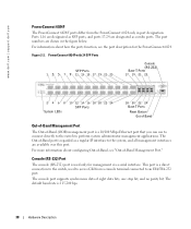
For information about configuring Out-of-Band, see the port description for management via a serial interface. The Out-of eight data bits, one stop bit, and no parity bit. This port is a direct connection to perform system administrator...10/100 Mbps Ethernet port that you can use to connect directly to the switch to the switch, used only for the PowerConnect 6024. Figure 2-2. www.dell.com | support.dell.com PowerConnect 6024F The PowerConnect 6024F ports differ from a console terminal connected to the system, and all management interfaces are designated as a regular IP ...
For information about configuring Out-of-Band, see the port description for management via a serial interface. The Out-of eight data bits, one stop bit, and no parity bit. This port is a direct connection to perform system administrator...10/100 Mbps Ethernet port that you can use to connect directly to the switch to the switch, used only for the PowerConnect 6024. Figure 2-2. www.dell.com | support.dell.com PowerConnect 6024F The PowerConnect 6024F ports differ from a console terminal connected to the system, and all management interfaces are designated as a regular IP ...

User's Guide (.htm)
Page 36
... on high or open 4 Module definition 2; data line for an optional SFP connector. Figure 3-2. www.dell.com | support.dell.com Table 3-1. Pin Connections for SFP Interfaces Figure 3-2 illustrates an SFP connector, and Table 3-2 shows the pin assignments for serial ID. 5 Module definition 1; clock line for 10/100/1000 Base T Pin Use 4 TxRx 2- 5 TxRx3...
... on high or open 4 Module definition 2; data line for an optional SFP connector. Figure 3-2. www.dell.com | support.dell.com Table 3-1. Pin Connections for SFP Interfaces Figure 3-2 illustrates an SFP connector, and Table 3-2 shows the pin assignments for serial ID. 5 Module definition 1; clock line for 10/100/1000 Base T Pin Use 4 TxRx 2- 5 TxRx3...
User's Guide (.htm)
Page 37
...) 11 Receiver ground (common with receiver ground). Figure 3-3 shows the serial cable and Table 3-3 shows the serial connector pin assignments. Cable, Port, and Pinout Information 47 Serial Cable Connection You can use serial cables (null-modem) to connect the switch to female DB-9 crossover...Pin Use 6 Module definition 0; AC coupled. 13 Receiver non-inverted data out; grounded within the module 7 Rate select; The switch's serial cable is female to a terminal for initial setup and configuration (You can also use a PC running terminal emulation software.). AC coupled....
...) 11 Receiver ground (common with receiver ground). Figure 3-3 shows the serial cable and Table 3-3 shows the serial connector pin assignments. Cable, Port, and Pinout Information 47 Serial Cable Connection You can use serial cables (null-modem) to connect the switch to female DB-9 crossover...Pin Use 6 Module definition 0; AC coupled. 13 Receiver non-inverted data out; grounded within the module 7 Rate select; The switch's serial cable is female to a terminal for initial setup and configuration (You can also use a PC running terminal emulation software.). AC coupled....

User's Guide (.htm)
Page 38
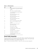
... RTS Unused Pin Management Console Port Signal 1 Unused 2 TXD 3 RXD 4 RXD 5 GND 6 Unused 7 CTS 8 RTS 9 Unused Connecting the Switch to a Terminal 1 Connect the null modem (serial) cable to the terminal (console) ASCII DTE RS-232 connection. 2 Connect the interface cable to the switch...
... RTS Unused Pin Management Console Port Signal 1 Unused 2 TXD 3 RXD 4 RXD 5 GND 6 Unused 7 CTS 8 RTS 9 Unused Connecting the Switch to a Terminal 1 Connect the null modem (serial) cable to the terminal (console) ASCII DTE RS-232 connection. 2 Connect the interface cable to the switch...
User's Guide (.htm)
Page 39
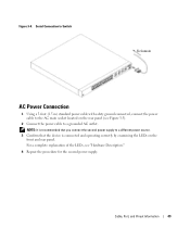
...: It is connected and operating correctly by examining the LEDs on the rear panel (see "Hardware Description." 4 Repeat the procedure for the second power supply. Serial Connection to Switch To Console AC Power Connection 1 Using a 5-foot (1.5 m) standard power cable with safety ground connected, connect the power cable to the AC main...
...: It is connected and operating correctly by examining the LEDs on the rear panel (see "Hardware Description." 4 Repeat the procedure for the second power supply. Serial Connection to Switch To Console AC Power Connection 1 Using a 5-foot (1.5 m) standard power cable with safety ground connected, connect the power cable to the AC main...
User's Guide (.htm)
Page 53
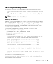
... the Switch When the power is detected, the program flow stops. POST runs every time the device is initialized and checks hardware components to the serial port (cross-cable) in 2 seconds - If a critical problem is turned on the switch. The boot process runs approximately 30 seconds. POST messages are displayed on...
... the Switch When the power is detected, the program flow stops. POST runs every time the device is initialized and checks hardware components to the serial port (cross-cable) in 2 seconds - If a critical problem is turned on the switch. The boot process runs approximately 30 seconds. POST messages are displayed on...
User's Guide (.htm)
Page 90
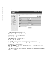
... is January 11, 2002. The format is hour, minute, second, for example, 11/Jan/02 is 8:12:03 PM. 100 Configuring System Information www.dell.com | support.dell.com To display the Asset page, click System→General→Asset in the tree view. Figure 6-2. Asset The Asset page contains the following...
... is January 11, 2002. The format is hour, minute, second, for example, 11/Jan/02 is 8:12:03 PM. 100 Configuring System Information www.dell.com | support.dell.com To display the Asset page, click System→General→Asset in the tree view. Figure 6-2. Asset The Asset page contains the following...
User's Guide (.htm)
Page 91
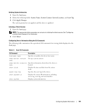
... initiating the telnet session. snmp-server contact Sets up a system contact. show system-id Displays the system ID information, including service tag, asset tag, and serial number. asset-tag tag Specifies the asset tag for viewing fields displayed in the Asset page. Table 6-1. Initiating a Telnet Session 1 Open the Asset page. NOTE...
... initiating the telnet session. snmp-server contact Sets up a system contact. show system-id Displays the system ID information, including service tag, asset tag, and serial number. asset-tag tag Specifies the asset tag for viewing fields displayed in the Asset page. Table 6-1. Initiating a Telnet Session 1 Open the Asset page. NOTE...

