Command Line Interface (CLI) Guide (.htm)
Page 67
...of these commands are the same as a single entity. d Select Terminal keys for Emulation mode. DELL CONFIDENTIAL - Most of 9600). The interface port-channel Global Configuration mode command is used to enter... access-list configuration mode.. Using the device command-line interface (CLI) is 115,200 (Console port on MAC addresses. NOTE: The default data rate, for example, assigning ports to manually... PROOF ONLY Using the CLI 67 Starting the CLI The device can be managed over cable to the RS-232 serial port of the terminal or computer running the terminal emulation ...
...of these commands are the same as a single entity. d Select Terminal keys for Emulation mode. DELL CONFIDENTIAL - Most of 9600). The interface port-channel Global Configuration mode command is used to enter... access-list configuration mode.. Using the device command-line interface (CLI) is 115,200 (Console port on MAC addresses. NOTE: The default data rate, for example, assigning ports to manually... PROOF ONLY Using the CLI 67 Starting the CLI The device can be managed over cable to the RS-232 serial port of the terminal or computer running the terminal emulation ...

Command Line Interface (CLI) Guide (.htm)
Page 157
.... DELL CONFIDENTIAL - Manual mdix • auto - FOR PROOF ONLY Ethernet Configuration Commands 157 Default Configuration Flow control is on. Console(config)# interface ethernet 1/e5 Console(config-if)# flowcontrol on mdix The mdix Interface Configuration (Ethernet) mode command enables cable crossover on - To disable cable crossover...and are automatically detected. • On: It is possible to connect to a PC only with a normal cable and to connect to another device only with a cross cable. • No: It is enabled on port 1/e5. Example In the following example, flow control is...
.... DELL CONFIDENTIAL - Manual mdix • auto - FOR PROOF ONLY Ethernet Configuration Commands 157 Default Configuration Flow control is on. Console(config)# interface ethernet 1/e5 Console(config-if)# flowcontrol on mdix The mdix Interface Configuration (Ethernet) mode command enables cable crossover on - To disable cable crossover...and are automatically detected. • On: It is possible to connect to a PC only with a normal cable and to connect to another device only with a cross cable. • No: It is enabled on port 1/e5. Example In the following example, flow control is...

Command Line Interface (CLI) Guide (.htm)
Page 231
DELL CONFIDENTIAL - PRELIMINARY 9/13/06 - Examples The following example results in a report on copper ports... the test, unless it is a combination port with fiber port active. • The maximum length of a copper cable attached to port 1/e3. PHY Diagnostics Commands test copper-port tdr The test copper-port tdr Privileged EXEC mode command uses... Time Domain Reflectometry (TDR) technology to diagnose the quality and characteristics of the cable for the TDR test is open at 64 meters Console# test copper-port tdr 2/e3 Can't perform this test on fiber ports show copper-...
DELL CONFIDENTIAL - PRELIMINARY 9/13/06 - Examples The following example results in a report on copper ports... the test, unless it is a combination port with fiber port active. • The maximum length of a copper cable attached to port 1/e3. PHY Diagnostics Commands test copper-port tdr The test copper-port tdr Privileged EXEC mode command uses... Time Domain Reflectometry (TDR) technology to diagnose the quality and characteristics of the cable for the TDR test is open at 64 meters Console# test copper-port tdr 2/e3 Can't perform this test on fiber ports show copper-...

Command Line Interface (CLI) Guide (.htm)
Page 232
...e2 1/e3 1/e4 1/e5 Result Length [meters] ------- -------- Command Mode User EXEC mode DELL CONFIDENTIAL - Command Mode User EXEC mode User Guidelines • The maximum length of the cable for the TDR test is 120 meter. OK Short 50 Test has not been performed ...has no default configuration. FOR PROOF ONLY 232 PHY Diagnostics Commands Console> show copper-ports cable-length User EXEC mode command displays the estimated copper cable length attached to a port. www.dell.com | support.dell.com show copper-ports cable-length [interface] • interface - Date ----- 13:32...
...e2 1/e3 1/e4 1/e5 Result Length [meters] ------- -------- Command Mode User EXEC mode DELL CONFIDENTIAL - Command Mode User EXEC mode User Guidelines • The maximum length of the cable for the TDR test is 120 meter. OK Short 50 Test has not been performed ...has no default configuration. FOR PROOF ONLY 232 PHY Diagnostics Commands Console> show copper-ports cable-length User EXEC mode command displays the estimated copper cable length attached to a port. www.dell.com | support.dell.com show copper-ports cable-length [interface] • interface - Date ----- 13:32...

Command Line Interface (CLI) Guide (.htm)
Page 233
Console> show copper-ports cable-length Port ---1/e1 1/e2 1/e3 1/g1 Length [meters 50 Copper not active 110-140 Fiber show fiber-ports optical-transceiver The show fiber-ports optical-transceiver [interface] [detailed] Syntax Description • interface - PRELIMINARY 9/13/06 - Example The following example displays the estimated copper cable length attached to all ports...
Console> show copper-ports cable-length Port ---1/e1 1/e2 1/e3 1/g1 Length [meters 50 Copper not active 110-140 Fiber show fiber-ports optical-transceiver The show fiber-ports optical-transceiver [interface] [detailed] Syntax Description • interface - PRELIMINARY 9/13/06 - Example The following example displays the estimated copper cable length attached to all ports...
User's Guide (.htm)
Page 10
...PowerConnect 3424 and PowerConnect 3424P . . . 21 PowerConnect 3448 and PowerConnect 3448P . . . 22 Stacking Ring Topology 23 PowerConnect 3448/P replaces PowerConnect 3448/P 26 PowerConect 3424/P port replaces PowerConnect 3448/P port 26 PowerConnect 3448/P port replaces PowerConect 3424/P Port 27 PowerConnect 3424 Front Panel 37 PowerConnect 3424 Back Panel 38 PowerConnect 3448 Front Panel 38 PowerConnect 3448 Back Panel 39 Console...Connector 54 Stacking Cable Diagram 55 Stacking Configuration and Identification Panel . . . 56 Connecting to PowerConnect 3400 Series Console Port 58 ...
...PowerConnect 3424 and PowerConnect 3424P . . . 21 PowerConnect 3448 and PowerConnect 3448P . . . 22 Stacking Ring Topology 23 PowerConnect 3448/P replaces PowerConnect 3448/P 26 PowerConect 3424/P port replaces PowerConnect 3448/P port 26 PowerConnect 3448/P port replaces PowerConect 3424/P Port 27 PowerConnect 3424 Front Panel 37 PowerConnect 3424 Back Panel 38 PowerConnect 3448 Front Panel 38 PowerConnect 3448 Back Panel 39 Console...Connector 54 Stacking Cable Diagram 55 Stacking Configuration and Identification Panel . . . 56 Connecting to PowerConnect 3400 Series Console Port 58 ...
User's Guide (.htm)
Page 50
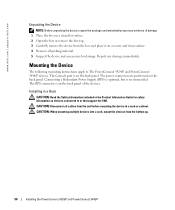
The Console port is on devices connected to The PowerConnect 3424/P and PowerConnect 3448/P devices. Installing in a Rack CAUTION: Read the Safety ...support the SWI. The power connectors are positioned on a secure and clean surface. 4 Remove all cables from the unit before mounting the device in the Product Information Guide for damage. The RPS connector ... material. 5 Inspect the device and accessories for safety information on the back panel. www.dell.com | support.dell.com Unpacking the Device NOTE: Before unpacking the device, inspect the package and immediately report ...
The Console port is on devices connected to The PowerConnect 3424/P and PowerConnect 3448/P devices. Installing in a Rack CAUTION: Read the Safety ...support the SWI. The power connectors are positioned on a secure and clean surface. 4 Remove all cables from the unit before mounting the device in the Product Information Guide for damage. The RPS connector ... material. 5 Inspect the device and accessories for safety information on the back panel. www.dell.com | support.dell.com Unpacking the Device NOTE: Before unpacking the device, inspect the package and immediately report ...
User's Guide (.htm)
Page 54
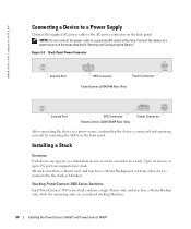
... and Configuring the Device". Figure 3-4. Back-Panel Power Connector Console Port RPS Connector Power Connector PowerConnect 3424/3448 Rear View Console Port EPS Connector PowerConnect 3424P/3448P Rear View Power Connector After connecting the device to...PowerConnect 3448/P Stacking PowerConnect 3400 Series Switches Each PowerConnect 3400 series stack contains a single Master unit, and may have a Master Backup unit, while the remaining units are supported per stack. Installing a Stack Overview Each device can operate as Members. NOTE: Do not connect the power cable...
... and Configuring the Device". Figure 3-4. Back-Panel Power Connector Console Port RPS Connector Power Connector PowerConnect 3424/3448 Rear View Console Port EPS Connector PowerConnect 3424P/3448P Rear View Power Connector After connecting the device to...PowerConnect 3448/P Stacking PowerConnect 3400 Series Switches Each PowerConnect 3400 series stack contains a single Master unit, and may have a Master Backup unit, while the remaining units are supported per stack. Installing a Stack Overview Each device can operate as Members. NOTE: Do not connect the power cable...
User's Guide (.htm)
Page 56
... a unique identifying unit ID that the stand-alone/Master device Console port is manually configured by using the Stack ID button. When...cable. 2 Locate an AC power receptacle. 3 Deactivate the AC power receptacle. 4 Connect the device to the AC receptacle. 5 Activate the AC power receptacle. The LED flashes for Member units. During this period, select a specific Stack ID by the Stack ID LEDs. The default setting is illuminated. 56 Installing the PowerConnect 3424/P and PowerConnect 3448.../P www.dell.com | support.dell.com Figure 3-6.
... a unique identifying unit ID that the stand-alone/Master device Console port is manually configured by using the Stack ID button. When...cable. 2 Locate an AC power receptacle. 3 Deactivate the AC power receptacle. 4 Connect the device to the AC receptacle. 5 Activate the AC power receptacle. The LED flashes for Member units. During this period, select a specific Stack ID by the Stack ID LEDs. The default setting is illuminated. 56 Installing the PowerConnect 3424/P and PowerConnect 3448.../P www.dell.com | support.dell.com Figure 3-6.
User's Guide (.htm)
Page 57
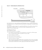
...the device, the device must be cabled as per the "Stacking Cable Diagram" before powering up and their Stack IDs are master-enabled units. However, the entire stack should be connected to the console. Starting and Configuring the Device ...Console port, the following is described in the section "Advanced Configuration". 6 Selection Process - The Stack ID button becomes unresponsive and the unit ID is completed when the 15-second flashing period has transpired. Installing the PowerConnect 3424/P and PowerConnect 3448/P 57 Download the release notes from the Dell...
...the device, the device must be cabled as per the "Stacking Cable Diagram" before powering up and their Stack IDs are master-enabled units. However, the entire stack should be connected to the console. Starting and Configuring the Device ...Console port, the following is described in the section "Advanced Configuration". 6 Selection Process - The Stack ID button becomes unresponsive and the unit ID is completed when the 15-second flashing period has transpired. Installing the PowerConnect 3424/P and PowerConnect 3448/P 57 Download the release notes from the Dell...

User's Guide (.htm)
Page 58
...Console port on the Master unit/stand-alone device, and tighten the captive retaining screws. NOTICE: When using HyperTerminal with Microsoft® Windows® 2000,ensure that the setting is for Terminal keys (not Windows keys). Go to www.microsoft.com for Function, Arrow, and Ctrl keys. www.dell.com | support.dell... female connector of the RS-232 crossover cable directly to the Console port on the rear panel. Ensure that...PowerConnect 3400 Series Console port is performed only from the stack master (unit ID 1 or 2). 58 Installing the PowerConnect 3424/P and PowerConnect 3448/P
...Console port on the Master unit/stand-alone device, and tighten the captive retaining screws. NOTICE: When using HyperTerminal with Microsoft® Windows® 2000,ensure that the setting is for Terminal keys (not Windows keys). Go to www.microsoft.com for Function, Arrow, and Ctrl keys. www.dell.com | support.dell... female connector of the RS-232 crossover cable directly to the Console port on the rear panel. Ensure that...PowerConnect 3400 Series Console port is performed only from the stack master (unit ID 1 or 2). 58 Installing the PowerConnect 3424/P and PowerConnect 3448/P

User's Guide (.htm)
Page 154
... to perform tests on Fiber Optic cables. Optical Transceiver 154 Configuring System Information Figure 6-37. Console# show copper-port cable-length Port Length (meters) ---- 1/e3 110-140 1/e4 Fiber NOTE: The cable length returned by the Integrated Cable Tester (ICT) is an approximation in the tree view. . www.dell.com | support.dell.com The following is an...
... to perform tests on Fiber Optic cables. Optical Transceiver 154 Configuring System Information Figure 6-37. Console# show copper-port cable-length Port Length (meters) ---- 1/e3 110-140 1/e4 Fiber NOTE: The cable length returned by the Integrated Cable Tester (ICT) is an approximation in the tree view. . www.dell.com | support.dell.com The following is an...
User's Guide (.htm)
Page 399
... 212 Backup master, 22 BGP, 388 BootP, 388 BPDU, 274, 291, 388 Bridge Protocol Data Unit, 388 Broadcast, 110, 112, 121 Buttons, 82 C Cables, 152, 154 CBC, 189 CIDR, 389 Cipher Block-Chaining, 189 CLI, 22, 34 Command Line Interface, 22, 34 Command Mode Overview, 84 Communities, 202 ...Configuration file, 213 Console, 124 CoS, 378 Critical, 124 D DC unit, 46 Debug, 124 Default Gateway, 135-136 Default settings, 220 Defining device information, 88 Defining MAC-Based...
... 212 Backup master, 22 BGP, 388 BootP, 388 BPDU, 274, 291, 388 Bridge Protocol Data Unit, 388 Broadcast, 110, 112, 121 Buttons, 82 C Cables, 152, 154 CBC, 189 CIDR, 389 Cipher Block-Chaining, 189 CLI, 22, 34 Command Line Interface, 22, 34 Command Mode Overview, 84 Communities, 202 ...Configuration file, 213 Console, 124 CoS, 378 Critical, 124 D DC unit, 46 Debug, 124 Default Gateway, 135-136 Default settings, 220 Defining device information, 88 Defining MAC-Based...


