User's Guide (.htm)
Page 3
Contents 1 Introduction System Description 21 PowerConnect 3424 21 PowerConnect 3424P 21 PowerConnect 3448 22 PowerConnect 3448P 22 Stacking Overview 22 Understanding the Stack Topology 23 Stacking Failover Topology 23 Stacking Members and Unit ID 23 Removing and Replacing Stacking Members 24 Exchanging Stacking Members 25 Switching from the Stack Master to the Backup Stack Master. . . . . . 27 Features Overview...
Contents 1 Introduction System Description 21 PowerConnect 3424 21 PowerConnect 3424P 21 PowerConnect 3448 22 PowerConnect 3448P 22 Stacking Overview 22 Understanding the Stack Topology 23 Stacking Failover Topology 23 Stacking Members and Unit ID 23 Removing and Replacing Stacking Members 24 Exchanging Stacking Members 25 Switching from the Stack Master to the Backup Stack Master. . . . . . 27 Features Overview...
User's Guide (.htm)
Page 4
...Gigabit Port LEDs 43 System LEDs 44 Power Supplies 45 Stack ID Button 47 Reset Button 47 Ventilation System 47 3 Installing the PowerConnect 3424/P and PowerConnect 3448/P Site Preparation 49 Unpacking 49 Package Contents 49 Unpacking the Device 50 Mounting the Device 50 Installing in a Rack 50 Installing... on a Wall 52 Connecting to a Terminal 53 Connecting a Device to a Power Supply 54 Installing a Stack 54 Overview 54 Stacking PowerConnect 3400 Series Switches 54 Unit ID Selection Process 56 Starting and Configuring the Device 57 Connecting to the Device 57 4 Contents
...Gigabit Port LEDs 43 System LEDs 44 Power Supplies 45 Stack ID Button 47 Reset Button 47 Ventilation System 47 3 Installing the PowerConnect 3424/P and PowerConnect 3448/P Site Preparation 49 Unpacking 49 Package Contents 49 Unpacking the Device 50 Mounting the Device 50 Installing in a Rack 50 Installing... on a Wall 52 Connecting to a Terminal 53 Connecting a Device to a Power Supply 54 Installing a Stack 54 Overview 54 Stacking PowerConnect 3400 Series Switches 54 Unit ID Selection Process 56 Starting and Configuring the Device 57 Connecting to the Device 57 4 Contents
User's Guide (.htm)
Page 5
4 Configuring PowerConnect 3424/P and 3448/P Configuration Procedures 59 Booting the Switch 60 Initial Configuration 61 Advanced Configuration 65 Retrieving an IP Address From a DHCP Server 65 Receiving an IP Address From a BOOTP ... 76 Auto-Negotiation 76 MDI/MDIX 76 Flow Control 76 Back Pressure 76 Switching Port Default Settings 77 5 Using Dell OpenManage Switch Administrator Starting the Application 79 Understanding the Interface 79 Device Representation 81 Using the Switch Administrator Buttons 82 Information Buttons 82 Device Management Buttons 82 Field Definitions 83...
4 Configuring PowerConnect 3424/P and 3448/P Configuration Procedures 59 Booting the Switch 60 Initial Configuration 61 Advanced Configuration 65 Retrieving an IP Address From a DHCP Server 65 Receiving an IP Address From a BOOTP ... 76 Auto-Negotiation 76 MDI/MDIX 76 Flow Control 76 Back Pressure 76 Switching Port Default Settings 77 5 Using Dell OpenManage Switch Administrator Starting the Application 79 Understanding the Interface 79 Device Representation 81 Using the Switch Administrator Buttons 82 Information Buttons 82 Device Management Buttons 82 Field Definitions 83...
User's Guide (.htm)
Page 21
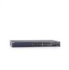
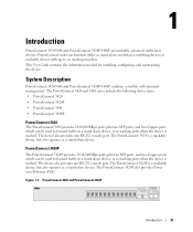
..., multi-layer, switching devices or stackable devices with minimal management. The device also provides one RS-232 console port. Figure 1-1. System Description PowerConnect 3424/3448 and PowerConnect 3424P/3448P combine versatility with up to six stacking members. The PowerConnect 3424 and 3448 series include the following device types: • PowerConnect 3424 • PowerConnect 3424P • PowerConnect 3448 • PowerConnect 3448P PowerConnect 3424 The PowerConnect 3424 provides 24...
..., multi-layer, switching devices or stackable devices with minimal management. The device also provides one RS-232 console port. Figure 1-1. System Description PowerConnect 3424/3448 and PowerConnect 3424P/3448P combine versatility with up to six stacking members. The PowerConnect 3424 and 3448 series include the following device types: • PowerConnect 3424 • PowerConnect 3424P • PowerConnect 3448 • PowerConnect 3448P PowerConnect 3424 The PowerConnect 3424 provides 24...
User's Guide (.htm)
Page 22
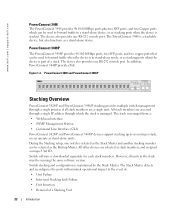
...operate as stand-alone units. PowerConnect 3448 and PowerConnect 3448P Stacking Overview PowerConnect 3424/P and PowerConnect 3448/P stacking provides multiple switch management through which can be ...used to forward traffic in stand-alone mode, or as stacking ports when the device is part of a Stacking Unit 22 Introduction Switch stacking and configuration is downloaded separately for each stack members. www.dell.com | support.dell.com PowerConnect 3448 The PowerConnect...
...operate as stand-alone units. PowerConnect 3448 and PowerConnect 3448P Stacking Overview PowerConnect 3424/P and PowerConnect 3448/P stacking provides multiple switch management through which can be ...used to forward traffic in stand-alone mode, or as stacking ports when the device is part of a Stacking Unit 22 Introduction Switch stacking and configuration is downloaded separately for each stack members. www.dell.com | support.dell.com PowerConnect 3448 The PowerConnect...
User's Guide (.htm)
Page 23
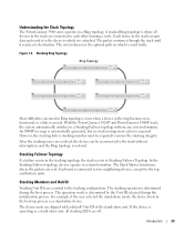
... occurs in a Ring topology. Each unit is connected to a Stacking Failover topology without interruption, and the Ring topology is required. With the PowerConnect 3424/P and PowerConnect 3448/P stack, the system automatically switches to two neighboring devices, except for the top and bottom units. An SNMP message is automatically generated, but no stack management action...
... occurs in a Ring topology. Each unit is connected to a Stacking Failover topology without interruption, and the Ring topology is required. With the PowerConnect 3424/P and PowerConnect 3448/P stack, the system automatically switches to two neighboring devices, except for the top and bottom units. An SNMP message is automatically generated, but no stack management action...
User's Guide (.htm)
Page 25
... replaced with a unit with the original device configuration. For example, • If a PowerConnect 3424/P replaces PowerConnect 3424/P, all port configurations remain the same. • If a PowerConnect 3448/P replaces the PowerConnect 3448/P, all configured ports is saved, even if the stack is used to configure the ...ID, the stack member is applied to boot without a selected Master, and the unit is not operating in the PowerConnect OpenManage Switch Administrator home page, and can be configured through topology discovery. If a unit attempts to the inserted stack member. ...
... replaced with a unit with the original device configuration. For example, • If a PowerConnect 3424/P replaces PowerConnect 3424/P, all port configurations remain the same. • If a PowerConnect 3448/P replaces the PowerConnect 3448/P, all configured ports is saved, even if the stack is used to configure the ...ID, the stack member is applied to boot without a selected Master, and the unit is not operating in the PowerConnect OpenManage Switch Administrator home page, and can be configured through topology discovery. If a unit attempts to the inserted stack member. ...
User's Guide (.htm)
Page 40
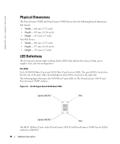
...Copper Based 10/100 BaseT LEDs Speed/LNK/ACT FDX Speed/LNK/ACT FDX The RJ-45 100 Base-T port on the PowerConnect 3424 /P and PowerConnect 3448/P has two LEDs marked as LNK/ACT. 40 Hardware Description The following physical dimensions: PoE Model: • Width... power supplies, fans, and system diagnostics. www.dell.com | support.dell.com Physical Dimensions The PowerConnect 3424/P and PowerConnect 3448/P devices have the following figure illustrates the 10/100 Base-T port LEDs on The PowerConnect 3424 /P and PowerConnect 3448/P switches: Figure 2-6. Port LEDs Each 10/100/1000 Base...
...Copper Based 10/100 BaseT LEDs Speed/LNK/ACT FDX Speed/LNK/ACT FDX The RJ-45 100 Base-T port on the PowerConnect 3424 /P and PowerConnect 3448/P has two LEDs marked as LNK/ACT. 40 Hardware Description The following physical dimensions: PoE Model: • Width... power supplies, fans, and system diagnostics. www.dell.com | support.dell.com Physical Dimensions The PowerConnect 3424/P and PowerConnect 3448/P devices have the following figure illustrates the 10/100 Base-T port LEDs on The PowerConnect 3424 /P and PowerConnect 3448/P switches: Figure 2-6. Port LEDs Each 10/100/1000 Base...
User's Guide (.htm)
Page 44
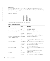
... of The PowerConnect 3424 /P and PowerConnect 3448/P devices...switch is turned on. System LED Indicators LED Power Supply (PWR) Redundant Power Supply (RPS) (models: 3424 and 3448 ) Redundant Power Supply (RPS) (models: 3424P...switch is turned off. The RPS is currently in . The following table describes the system LED indications. Green Static The system diagnostic test passed successfully. Green Flashing The system diagnostic test is currently operating. System LEDs The following figure illustrates the system LEDS. The RPS is currently operating. www.dell.com | support.dell...
... of The PowerConnect 3424 /P and PowerConnect 3448/P devices...switch is turned on. System LED Indicators LED Power Supply (PWR) Redundant Power Supply (RPS) (models: 3424 and 3448 ) Redundant Power Supply (RPS) (models: 3424P...switch is turned off. The RPS is currently in . The following table describes the system LED indications. Green Static The system diagnostic test passed successfully. Green Flashing The system diagnostic test is currently operating. System LEDs The following figure illustrates the system LEDS. The RPS is currently operating. www.dell.com | support.dell...
User's Guide (.htm)
Page 45
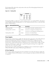
... LED lit, indicating its Unit ID number. The device is regulated through load sharing. The PowerConnect 3424/P and PowerConnect 3448/P devices have an internal power supply of the power supply. Hardware Description 45 Power supply...switch is either the Stack Master or Backup Master. Power Supplies The device has an internal power supply unit (AC unit) and a connector to connect PowerConnect 3424/P and PowerConnect 3448/P devices to a PowerConnect EPS-470 unit, or to connect PowerConnect 3424 and PowerConnect 3448 devices to 63 Hz. The PowerConnect 3424/P and PowerConnect...
... LED lit, indicating its Unit ID number. The device is regulated through load sharing. The PowerConnect 3424/P and PowerConnect 3448/P devices have an internal power supply of the power supply. Hardware Description 45 Power supply...switch is either the Stack Master or Backup Master. Power Supplies The device has an internal power supply unit (AC unit) and a connector to connect PowerConnect 3424/P and PowerConnect 3448/P devices to a PowerConnect EPS-470 unit, or to connect PowerConnect 3424 and PowerConnect 3448 devices to 63 Hz. The PowerConnect 3424/P and PowerConnect...
User's Guide (.htm)
Page 46
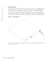
.... See Table 2-5 for RPS LED definition. Power Connection When the device is connected to provide a redundant power option. The PowerConnect 3424/P and PowerConnect 3448/P switches connect to an external EPS-470 unit to a different power source, the probability of failure in the event of a power ...RPS-600 is required. Figure 2-11. See Table 2-5 for RPS LED definition. No configuration is connected. www.dell.com | support.dell.com DC Power Supply Unit The PowerConnect 3424 and PowerConnect 3448 switches connect to an external RPS-600 unit to provide a redundant power option.
.... See Table 2-5 for RPS LED definition. Power Connection When the device is connected to provide a redundant power option. The PowerConnect 3424/P and PowerConnect 3448/P switches connect to an external EPS-470 unit to a different power source, the probability of failure in the event of a power ...RPS-600 is required. Figure 2-11. See Table 2-5 for RPS LED definition. No configuration is connected. www.dell.com | support.dell.com DC Power Supply Unit The PowerConnect 3424 and PowerConnect 3448 switches connect to an external RPS-600 unit to provide a redundant power option.
User's Guide (.htm)
Page 47
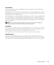
... the Master unit, the third member is 3, and the fourth Stack member is faulty. Hardware Description 47 Ventilation System The PowerConnect 3424/P and PowerConnect 3448/P switches with the PoE feature have a reset button, located on the Unit ID of the device. The Stack Master receives the ...Unit ID of booting the device. For example, if there are not reset. Reset Button The PowerConnect 3424/P and PowerConnect 3448/P switches have five built-in a stack, the Master unit is either 1 or 2, the backup Master is not elected functions as ...
... the Master unit, the third member is 3, and the fourth Stack member is faulty. Hardware Description 47 Ventilation System The PowerConnect 3424/P and PowerConnect 3448/P switches with the PoE feature have a reset button, located on the Unit ID of the device. The Stack Master receives the ...Unit ID of booting the device. For example, if there are not reset. Reset Button The PowerConnect 3424/P and PowerConnect 3448/P switches have five built-in a stack, the Master unit is either 1 or 2, the backup Master is not elected functions as ...
User's Guide (.htm)
Page 49
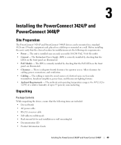
Installing the PowerConnect 3424/P and PowerConnect 3448/P Site Preparation The PowerConnect 3424 /P and PowerConnect 3448/P devices can be mounted in a standard 48.26-am (19-inch) equipment rack, placed on a tabletop or mounted on the front panel are included: • Device/Switch • AC power cable • RS-232 crossover cable • Self-adhesive rubber pads &#...-60 Hz outlet. • General - Allow clearance for rack installation or wall mounting kit • Documentation CD • Product Information Guide Installing the PowerConnect 3424/P and PowerConnect 3448/P 49
Installing the PowerConnect 3424/P and PowerConnect 3448/P Site Preparation The PowerConnect 3424 /P and PowerConnect 3448/P devices can be mounted in a standard 48.26-am (19-inch) equipment rack, placed on a tabletop or mounted on the front panel are included: • Device/Switch • AC power cable • RS-232 crossover cable • Self-adhesive rubber pads &#...-60 Hz outlet. • General - Allow clearance for rack installation or wall mounting kit • Documentation CD • Product Information Guide Installing the PowerConnect 3424/P and PowerConnect 3448/P 49
User's Guide (.htm)
Page 54
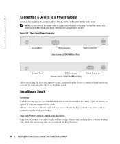
...PowerConnect 3400 Series Switches Each PowerConnect 3400 series stack contains a single Master unit, and may have a Master Backup unit, while the remaining units are supported per stack. NOTE: Do not connect the power cable to 192 ports are considered stacking Members. 54 Installing the PowerConnect 3424/P and PowerConnect... 3448/P Installing a Stack Overview Each device can operate as Members. www.dell.com | support.dell... Connector Power Connector PowerConnect 3424/3448 Rear View Console Port EPS Connector PowerConnect 3424P/3448P Rear View...
...PowerConnect 3400 Series Switches Each PowerConnect 3400 series stack contains a single Master unit, and may have a Master Backup unit, while the remaining units are supported per stack. NOTE: Do not connect the power cable to 192 ports are considered stacking Members. 54 Installing the PowerConnect 3424/P and PowerConnect... 3448/P Installing a Stack Overview Each device can operate as Members. www.dell.com | support.dell... Connector Power Connector PowerConnect 3424/3448 Rear View Console Port EPS Connector PowerConnect 3424P/3448P Rear View...

User's Guide (.htm)
Page 55
PowerConnect 3400 series switches use the RJ-45 Gigabit Ethernet ports (G3 and G4) for stacking. To stack the devices together, insert a standard Category 5 cable into port G3 in ... all devices are not displayed in the stack. Stacking Cable Diagram NOTE: In stacking mode ports designated as G3 and G4 are connected. Installing the PowerConnect 3424/P and PowerConnect 3448/P 55
PowerConnect 3400 series switches use the RJ-45 Gigabit Ethernet ports (G3 and G4) for stacking. To stack the devices together, insert a standard Category 5 cable into port G3 in ... all devices are not displayed in the stack. Stacking Cable Diagram NOTE: In stacking mode ports designated as G3 and G4 are connected. Installing the PowerConnect 3424/P and PowerConnect 3448/P 55
User's Guide (.htm)
Page 60
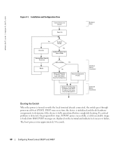
...PowerConnect 3424/P and 3448/P www.dell.com | support.dell.com Figure 4-1. Installation and Configuration Flow Connect Device and Console Power On Hardware Setup Press Esc Yes Susepnd Bootup No Loading Program from flash to determine if the device is turned on with the local terminal already connected, the switch... Advanced Configuration: IP Address from DHCP, IP address from bootp, Security Management Advanced Device Installation Booting the Switch When the power is fully operational before completely booting. If POST passes successfully, a valid executable image is...
...PowerConnect 3424/P and 3448/P www.dell.com | support.dell.com Figure 4-1. Installation and Configuration Flow Connect Device and Console Power On Hardware Setup Press Esc Yes Susepnd Bootup No Loading Program from flash to determine if the device is turned on with the local terminal already connected, the switch... Advanced Configuration: IP Address from DHCP, IP address from bootp, Security Management Advanced Device Installation Booting the Switch When the power is fully operational before completely booting. If POST passes successfully, a valid executable image is...
User's Guide (.htm)
Page 61
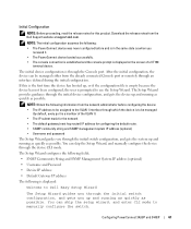
... IP address for this is through the initial switch configuration, and gets you received it. • The PowerConnect device booted successfully. • The console connection is established and the console prompt is to use the Setup Wizard. Configuring PowerConnect 3424/P and 3448/P 61 You can skip the ... the device: • The IP address to be managed either from the Dell Support website at support.dell.com. NOTE: The initial configuration assumes the following is displayed: Welcome to Dell Easy Setup Wizard The Setup Wizard guides you through the Console port. If this...
... IP address for this is through the initial switch configuration, and gets you received it. • The PowerConnect device booted successfully. • The console connection is established and the console prompt is to use the Setup Wizard. Configuring PowerConnect 3424/P and 3448/P 61 You can skip the ... the device: • The IP address to be managed either from the Dell Support website at support.dell.com. NOTE: The initial configuration assumes the following is displayed: Welcome to Dell Easy Setup Wizard The Setup Wizard guides you through the Console port. If this...
User's Guide (.htm)
Page 62
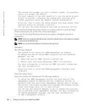
...the particular management system uses to enter the Setup Wizard (you must answer this account. If you like to access the switch. You can use Dell Network Manager or CLI to change this setting, and to Step 2. Would you like to setup the SNMP management interface ...CLI console prompt appears. To add a management station: 62 Configuring PowerConnect 3424/P and 3448/P If there is not setup for Dell Network Manager) you with normal operation using the default system configuration. To manage the switch using SNMP (required for SNMP management by entering [ctrl+Z]. NOTE:...
...the particular management system uses to enter the Setup Wizard (you must answer this account. If you like to access the switch. You can use Dell Network Manager or CLI to change this setting, and to Step 2. Would you like to setup the SNMP management interface ...CLI console prompt appears. To add a management station: 62 Configuring PowerConnect 3424/P and 3448/P If there is not setup for Dell Network Manager) you with normal operation using the default system configuration. To manage the switch using SNMP (required for SNMP management by entering [ctrl+Z]. NOTE:...
User's Guide (.htm)
Page 63
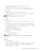
... entries are not identical, the user is displayed: Now we need to access the CLI, Web interface, or SNMP interface for the switch.To setup an IP address: Configuring PowerConnect 3424/P and 3448/P 63 This is defined on setting up user accounts and changing privilege levels, see the user documentation. The IP address...
... entries are not identical, the user is displayed: Now we need to access the CLI, Web interface, or SNMP interface for the switch.To setup an IP address: Configuring PowerConnect 3424/P and 3448/P 63 This is defined on setting up user accounts and changing privilege levels, see the user documentation. The IP address...
User's Guide (.htm)
Page 76
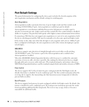
... support auto-negotiation or is disabled) abilities to operate in half duplex. www.dell.com | support.dell.com Port Default Settings The general information for configuring the device ports includes the ... flow control default is not set to prevent buffer overflow. If the station on all switching 10/100/1000BaseT ports. The flow control mechanism allows the receiving side to signal to... supports back pressure for additional traffic. 76 Configuring PowerConnect 3424/P and 3448/P Auto-negotiation is enabled. The back-pressure mechanism prevents the sender from transmitting ...
... support auto-negotiation or is disabled) abilities to operate in half duplex. www.dell.com | support.dell.com Port Default Settings The general information for configuring the device ports includes the ... flow control default is not set to prevent buffer overflow. If the station on all switching 10/100/1000BaseT ports. The flow control mechanism allows the receiving side to signal to... supports back pressure for additional traffic. 76 Configuring PowerConnect 3424/P and 3448/P Auto-negotiation is enabled. The back-pressure mechanism prevents the sender from transmitting ...


