
Information Update
Page 1
...; By enabling DHCP Addressing NOTE: To update the IP address, see the Dell PowerConnect 27xx Systems User's Guide. NOTE: The Managed Mode button is reset to take advantage of the management features of the switch, see "Viewing System IP Address" in the User's Guide, press the Managed... configured with a default IP address (192.168.2.1) and a default user login (User Name: admin and no password). The switch changes to the instructions in Dell PowerConnect 27xx Systems User's Guide. NOTE: To access the device through the Web interface, see "Initial Configuration" in the User's ...
...; By enabling DHCP Addressing NOTE: To update the IP address, see the Dell PowerConnect 27xx Systems User's Guide. NOTE: The Managed Mode button is reset to take advantage of the management features of the switch, see "Viewing System IP Address" in the User's Guide, press the Managed... configured with a default IP address (192.168.2.1) and a default user login (User Name: admin and no password). The switch changes to the instructions in Dell PowerConnect 27xx Systems User's Guide. NOTE: To access the device through the Web interface, see "Initial Configuration" in the User's ...
Getting Started Guide
Page 5
Contents Installation 5 Overview 5 Site Preparation 5 Unpacking 5 Mounting the Device 6 Starting and Configuring the Device 10 Booting the Switch 10 Initial Configuration 10 Contents 3
Contents Installation 5 Overview 5 Site Preparation 5 Unpacking 5 Mounting the Device 6 Starting and Configuring the Device 10 Booting the Switch 10 Initial Configuration 10 Contents 3
Getting Started Guide
Page 7
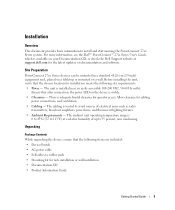
... are included: • Device/Switch • AC power cable • Self-adhesive rubber pads • Mounting kit for operator access. The cabling is 0 to 45ºC (32 to 113ºF) at support.dell.com for cabling, power connections, and ventilation. • Cabling - For more information, see the Dell™ PowerConnect™ 27xx Series User...
... are included: • Device/Switch • AC power cable • Self-adhesive rubber pads • Mounting kit for operator access. The cabling is 0 to 45ºC (32 to 113ºF) at support.dell.com for cabling, power connections, and ventilation. • Cabling - For more information, see the Dell™ PowerConnect™ 27xx Series User...
Getting Started Guide
Page 9
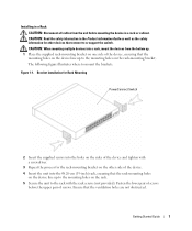
... that the ventilation holes are not obstructed. The following figure illustrates where to mount the brackets. Bracket Installation for Rack Mounting PowerConnect Switch 2 Insert the supplied screws into the holes on the sides of the device and tighten with the rack screws (not provided). CAUTION: When mounting multiple ...
... that the ventilation holes are not obstructed. The following figure illustrates where to mount the brackets. Bracket Installation for Rack Mounting PowerConnect Switch 2 Insert the supplied screws into the holes on the sides of the device and tighten with the rack screws (not provided). CAUTION: When mounting multiple ...
Getting Started Guide
Page 10
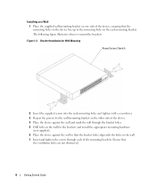
Bracket Installation for Wall Mounting PowerConnect Switch 2 Insert the supplied screws into the rack-mounting holes and tighten with the holes in the wall. 7 Insert and tighten the screws through the bracket ...
Bracket Installation for Wall Mounting PowerConnect Switch 2 Insert the supplied screws into the rack-mounting holes and tighten with the holes in the wall. 7 Insert and tighten the screws through the bracket ...
Getting Started Guide
Page 11
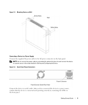
Back-Panel Power Connectors PowerConnect Switch Rear View Power Connector Connect the device to a power source in the steps detailed in Starting and Configuring the Device. You will connect the device ...
Back-Panel Power Connectors PowerConnect Switch Rear View Power Connector Connect the device to a power source in the steps detailed in Starting and Configuring the Device. You will connect the device ...

Getting Started Guide
Page 12
... pre configured default IP (192.168.2.1) and subnet mask (255.255.255.0). • The PowerConnect device booted successfully. NOTE: Obtain the following assumptions: • The PowerConnect device is configured with the system specific configuration. NOTE: It is recommended that power is being...approximately 90 seconds. You can download the release notes from the Dell Support website at support.dell.com. Starting and Configuring the Device NOTE: The device is designed to function as an unmanaged switch. To use the management functions, refer the configuration options and ...
... pre configured default IP (192.168.2.1) and subnet mask (255.255.255.0). • The PowerConnect device booted successfully. NOTE: Obtain the following assumptions: • The PowerConnect device is configured with the system specific configuration. NOTE: It is recommended that power is being...approximately 90 seconds. You can download the release notes from the Dell Support website at support.dell.com. Starting and Configuring the Device NOTE: The device is designed to function as an unmanaged switch. To use the management functions, refer the configuration options and ...

Getting Started Guide
Page 13
... the IP Address, Subnet Mask and Default Gateway. 4 Click Apply Changes. Getting Started Guide 11 For more information on the management capabilities of the switch, please refer the PowerConnect 27xx Series User's Guide found on the steps necessary for basic setup of a web browser. To configure the device: 1 Open the web management... user interface, Click IP Addressing. The device is configured. To do so, enter the IP address of the device in the URL field of the switch. NOTE: This getting started guide provides information on your documenatation CD.
... the IP Address, Subnet Mask and Default Gateway. 4 Click Apply Changes. Getting Started Guide 11 For more information on the management capabilities of the switch, please refer the PowerConnect 27xx Series User's Guide found on the steps necessary for basic setup of a web browser. To configure the device: 1 Open the web management... user interface, Click IP Addressing. The device is configured. To do so, enter the IP address of the device in the URL field of the switch. NOTE: This getting started guide provides information on your documenatation CD.
Readme
Page 3
... to installing the software on the PowerConnect 2748 switch. For information about loading the boot PROM software and updating the firmware image, see the Dell Support website at support.dell.com. Denotes an ad hoc release of this product. Global Support For information regarding firmware updates, release notes, or additional assistance, see the Dell PowerConnect 2748 User's Guide.
... to installing the software on the PowerConnect 2748 switch. For information about loading the boot PROM software and updating the firmware image, see the Dell Support website at support.dell.com. Denotes an ad hoc release of this product. Global Support For information regarding firmware updates, release notes, or additional assistance, see the Dell PowerConnect 2748 User's Guide.

User's Guide
Page 3
... Address Supported Features 11 Layer 2 Features 11 VLAN Supported Features 12 Class of Service (CoS) Features 12 Ethernet Switch Management Features 13 Port Default Settings 13 2 Hardware Description Switch Port Configurations 15 PowerConnect 2708/2716/2724/2748 Front Panel Port Description . . . . 15 Physical Dimensions 19 LED Definitions 19 Power LED 19 Managed Mode LED...
... Address Supported Features 11 Layer 2 Features 11 VLAN Supported Features 12 Class of Service (CoS) Features 12 Ethernet Switch Management Features 13 Port Default Settings 13 2 Hardware Description Switch Port Configurations 15 PowerConnect 2708/2716/2724/2748 Front Panel Port Description . . . . 15 Physical Dimensions 19 LED Definitions 19 Power LED 19 Managed Mode LED...
User's Guide
Page 4
Power Connectors 24 Internal Power Supply Connector 24 3 Installing the Dell™ PowerConnect™ 27XX Installation Precautions 25 Overview 25 Site Requirements 26 Unpacking 26 Safety 26 Handling Static...the Network 32 4 Starting and Configuring the Dell™ PowerConnect™ 27XX Viewing Switch Operation 33 Initial Configuration 33 5 Using the Dell™ OpenManage™ Switch Administrator Understanding the Interface 37 Using the OpenManage Switch Administrator Buttons 39 Information Buttons 39 PowerConnect Switch Management Buttons 39 Starting the Application 40 ...
Power Connectors 24 Internal Power Supply Connector 24 3 Installing the Dell™ PowerConnect™ 27XX Installation Precautions 25 Overview 25 Site Requirements 26 Unpacking 26 Safety 26 Handling Static...the Network 32 4 Starting and Configuring the Dell™ PowerConnect™ 27XX Viewing Switch Operation 33 Initial Configuration 33 5 Using the Dell™ OpenManage™ Switch Administrator Understanding the Interface 37 Using the OpenManage Switch Administrator Buttons 39 Information Buttons 39 PowerConnect Switch Management Buttons 39 Starting the Application 40 ...

User's Guide
Page 5
Resetting the Device 41 Displaying Configuration on Demand 42 6 Configuring System Information Defining Switch Information 43 Viewing the Switch Status 43 Viewing System IP Address 44 Defining Interface Configuration 47 Viewing Jumbo Frames 49 Creating VLAN Membership 50 Defining VLAN Interface Settings 51 Configuring ...
Resetting the Device 41 Displaying Configuration on Demand 42 6 Configuring System Information Defining Switch Information 43 Viewing the Switch Status 43 Viewing System IP Address 44 Defining Interface Configuration 47 Viewing Jumbo Frames 49 Creating VLAN Membership 50 Defining VLAN Interface Settings 51 Configuring ...
User's Guide
Page 7
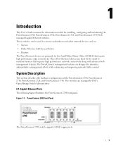
...) • Routers The PowerConnect devices are managed by Dell's OpenManage Switch Administrator. 8 1-Gigabit Ethernet Ports The following figure illustrates the PowerConnect 2708 front panel. The switches are primarily for installing, configuring and maintaining the PowerConnect 2708, PowerConnect 2716, PowerConnect 2724, and PowerConnect 2748 Webmanaged Gigabit Ethernet switches. PowerConnect 2708 Front Panel The PowerConnect 2708 switch supports 8 GbE copper ports. 7 These switches can be used to...
...) • Routers The PowerConnect devices are managed by Dell's OpenManage Switch Administrator. 8 1-Gigabit Ethernet Ports The following figure illustrates the PowerConnect 2708 front panel. The switches are primarily for installing, configuring and maintaining the PowerConnect 2708, PowerConnect 2716, PowerConnect 2724, and PowerConnect 2748 Webmanaged Gigabit Ethernet switches. PowerConnect 2708 Front Panel The PowerConnect 2708 switch supports 8 GbE copper ports. 7 These switches can be used to...
User's Guide
Page 8
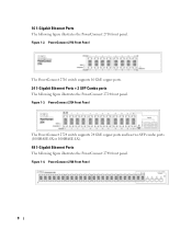
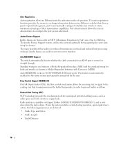
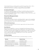
... The following figure illustrates the PowerConnect 2748 front panel. PowerConnect 2724 Front Panel The PowerConnect 2724 switch supports 24 GbE copper ports and has two SFP combo ports (1000BASE-SX or 1000BASE-LX). 48 1-Gigabit Ethernet Ports The following figure illustrates the PowerConnect 2716 front panel. Figure 1-2. PowerConnect 2716 Front Panel The PowerConnect 2716 switch supports 16 GbE copper...
... The following figure illustrates the PowerConnect 2748 front panel. PowerConnect 2724 Front Panel The PowerConnect 2724 switch supports 24 GbE copper ports and has two SFP combo ports (1000BASE-SX or 1000BASE-LX). 48 1-Gigabit Ethernet Ports The following figure illustrates the PowerConnect 2716 front panel. Figure 1-2. PowerConnect 2716 Front Panel The PowerConnect 2716 switch supports 16 GbE copper...

User's Guide
Page 9
...delays and frame loss caused by occupying the link so that it prevents users from making any further configuration changes to the switch. The switch does not have an IP address, nor is the system default. The default status on the whole system. Operates independent ...Mode button is done by the user configuring the switch in Managed Mode, configures the switch as desired, and then switches to the switch so that the HOL blocking prevention mechanism is pressed, the switch enters Unmanaged Mode. • Secure Mode (PowerConnect 2748 only) - Secure Mode works by removing the...
...delays and frame loss caused by occupying the link so that it prevents users from making any further configuration changes to the switch. The switch does not have an IP address, nor is the system default. The default status on the whole system. Operates independent ...Mode button is done by the user configuring the switch in Managed Mode, configures the switch as desired, and then switches to the switch so that the HOL blocking prevention mechanism is pressed, the switch enters Unmanaged Mode. • Secure Mode (PowerConnect 2748 only) - Secure Mode works by removing the...
User's Guide
Page 10
... are frames with Crossover (MDIX). The Jumbo Frames Support feature, utilizes the network optimally by the user. AutoMDI/MDIX Support The switch automatically detects whether the cable connected to configure the port speeds advertised. Standard wiring for end stations is Media-Dependent Interface (MDI)... and the standard wiring for hubs and switches is crossed or straight through. Flow Control Support (IEEE802.3X) On Full Duplex links (FDX), the flow control mechanism allows the...
... are frames with Crossover (MDIX). The Jumbo Frames Support feature, utilizes the network optimally by the user. AutoMDI/MDIX Support The switch automatically detects whether the cable connected to configure the port speeds advertised. Standard wiring for end stations is Media-Dependent Interface (MDI)... and the standard wiring for hubs and switches is crossed or straight through. Flow Control Support (IEEE802.3X) On Full Duplex links (FDX), the flow control mechanism allows the...

User's Guide
Page 11
... a given period of the VLAN tag. MAC Address Supported Features MAC Address Capacity Support The PowerConnect 2708, 2716, and 2724 switches support a total of 8K MAC addresses, and the PowerConnect 2748 supports a total of all ports on both the network links and the host operating system. ...11 Classic bridging (IEEE802.1D) is received for untagged frames. Unmanaged Mode Classic Bridging In Unmanaged Mode, the switch performs classic bridging. Users can...
... a given period of the VLAN tag. MAC Address Supported Features MAC Address Capacity Support The PowerConnect 2708, 2716, and 2724 switches support a total of 8K MAC addresses, and the PowerConnect 2748 supports a total of all ports on both the network links and the host operating system. ...11 Classic bridging (IEEE802.1D) is received for untagged frames. Unmanaged Mode Classic Bridging In Unmanaged Mode, the switch performs classic bridging. Users can...

User's Guide
Page 12
... (CoS) Features The PowerConnect 2708/2716/2724/2748 system enables users to form a single Link Aggregated Group (LAG). DHCP service is a corrupted or invalid software image. Class of the six aggregated links may be defined with up to full-duplex operation. The switches support four queues per port...to the TFTP client and try to VLANs based on the default VLAN, until a BootP server replies. Link Aggregation The PowerConnect 2708/2716/2724/2748 switches support up to four member ports to define various services for supporting bandwidth management and control is then used to be ...
... (CoS) Features The PowerConnect 2708/2716/2724/2748 system enables users to form a single Link Aggregated Group (LAG). DHCP service is a corrupted or invalid software image. Class of the six aggregated links may be defined with up to full-duplex operation. The switches support four queues per port...to the TFTP client and try to VLANs based on the default VLAN, until a BootP server replies. Link Aggregation The PowerConnect 2708/2716/2724/2748 switches support up to four member ports to define various services for supporting bandwidth management and control is then used to be ...
User's Guide
Page 13
The PowerConnect 2708/2716/2724/2748 system can be monitored and configured. No bandwidth reservations or limits are as follows: Function Flow Control (user-configurable) Backpressure (user-configurable) Auto ...The 802.1p is a spinoff of Service. TFTP Trivial File Transfer Protocol The PowerConnect 2708/2716/2724/2748 switches support software boot image and software download through which provides network traffic statistics. Port Default Settings The PowerConnect 2708/2716/2724/2748 devices's port default settings are established or enforced. The system contains an Embedded...
The PowerConnect 2708/2716/2724/2748 system can be monitored and configured. No bandwidth reservations or limits are as follows: Function Flow Control (user-configurable) Backpressure (user-configurable) Auto ...The 802.1p is a spinoff of Service. TFTP Trivial File Transfer Protocol The PowerConnect 2708/2716/2724/2748 switches support software boot image and software download through which provides network traffic statistics. Port Default Settings The PowerConnect 2708/2716/2724/2748 devices's port default settings are established or enforced. The system contains an Embedded...

User's Guide
Page 15
On each port there are numbered 1 to 8, top down and left side of the PowerConnect 2708/2716/2724/2748 switches. The Power LED on or not. The Gigabit Ethernet ports can only operate at 10, 100 or 1000 Mbps. ...support autonegotiation, duplex mode (Half or Full duplex), and flow control. Figure 2-1. 2 Hardware Description Switch Port Configurations PowerConnect 2708/2716/2724/2748 Front Panel Port Description The Dell™ PowerConnect™ 2708, 2716, 2724 and 2748 switches use 10/100/1000BASE-T ports on the front panel, restores the device's default settings configuration. 15...
On each port there are numbered 1 to 8, top down and left side of the PowerConnect 2708/2716/2724/2748 switches. The Power LED on or not. The Gigabit Ethernet ports can only operate at 10, 100 or 1000 Mbps. ...support autonegotiation, duplex mode (Half or Full duplex), and flow control. Figure 2-1. 2 Hardware Description Switch Port Configurations PowerConnect 2708/2716/2724/2748 Front Panel Port Description The Dell™ PowerConnect™ 2708, 2716, 2724 and 2748 switches use 10/100/1000BASE-T ports on the front panel, restores the device's default settings configuration. 15...


