
Information Update
Page 1
... Name: admin and no password). It is advisable to the instructions in Dell PowerConnect 27xx Systems User's Guide. Enabling Web-Managed Mode After powering up as unmanaged switches. March 2005 NOTE: All PowerConnect 27xx series switches have the same default IP address. In this switch, ...when the switch is recessed to Web-managed mode and the Managed Mode LED will be illuminated green. NOTE: The Managed Mode button is a toggle button located on the management capabilities of the switch, see "Initial Configuration" in Dell PowerConnect 27xx Systems User's Guide Logging In ...
... Name: admin and no password). It is advisable to the instructions in Dell PowerConnect 27xx Systems User's Guide. Enabling Web-Managed Mode After powering up as unmanaged switches. March 2005 NOTE: All PowerConnect 27xx series switches have the same default IP address. In this switch, ...when the switch is recessed to Web-managed mode and the Managed Mode LED will be illuminated green. NOTE: The Managed Mode button is a toggle button located on the management capabilities of the switch, see "Initial Configuration" in Dell PowerConnect 27xx Systems User's Guide Logging In ...
Information Update
Page 2
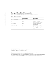
Resets each time you change without the written permission of Dell Inc. Dell Inc. Table 1. Reproduction in trademarks and trade names other than its own. www.dell.com | support.dell.com Managed Mode Default Configuration Table 1 shows the default configuration of Dell Inc. Default Configuration Managed Mode LED IP Unmanaged Mode Off None User Database None Configuration Db...
Resets each time you change without the written permission of Dell Inc. Dell Inc. Table 1. Reproduction in trademarks and trade names other than its own. www.dell.com | support.dell.com Managed Mode Default Configuration Table 1 shows the default configuration of Dell Inc. Default Configuration Managed Mode LED IP Unmanaged Mode Off None User Database None Configuration Db...

Getting Started Guide
Page 12
...Obtain the following assumptions: • The PowerConnect device is configured with the pre configured default IP (192.168.2.1) and subnet mask (255.255.255.0). • The PowerConnect device booted successfully. To use the management functions, refer the configuration options and ...details in the User's Guide. Initial Configuration NOTE: The initial configuration uses the following information from the Dell Support website at support.dell.com. Starting and...
...Obtain the following assumptions: • The PowerConnect device is configured with the pre configured default IP (192.168.2.1) and subnet mask (255.255.255.0). • The PowerConnect device booted successfully. To use the management functions, refer the configuration options and ...details in the User's Guide. Initial Configuration NOTE: The initial configuration uses the following information from the Dell Support website at support.dell.com. Starting and...

Getting Started Guide
Page 13
...3 Enter the IP Address, Subnet Mask and Default Gateway. 4 Click Apply Changes. The device is configured. To configure the device: 1 Open the web management interface (from any desktop or workstation). Getting Started Guide 11 To do so, enter the IP address of the device in the URL field of... the switch. For more information on the management capabilities of the switch, please refer the PowerConnect 27xx Series User's Guide found on the steps necessary for basic setup of a web browser. NOTE: This getting started guide...
...3 Enter the IP Address, Subnet Mask and Default Gateway. 4 Click Apply Changes. The device is configured. To configure the device: 1 Open the web management interface (from any desktop or workstation). Getting Started Guide 11 To do so, enter the IP address of the device in the URL field of... the switch. For more information on the management capabilities of the switch, please refer the PowerConnect 27xx Series User's Guide found on the steps necessary for basic setup of a web browser. NOTE: This getting started guide...

User's Guide
Page 3
...Features 11 VLAN Supported Features 12 Class of Service (CoS) Features 12 Ethernet Switch Management Features 13 Port Default Settings 13 2 Hardware Description Switch Port Configurations 15 PowerConnect 2708/2716/2724/2748 Front Panel Port Description . . . . 15 Physical Dimensions 19 LED Definitions ...19 Power LED 19 Managed Mode LED 19 Fan LED (2748 only 20 Port LEDs 20 Managed Mode Button 21 Switch Ventilation Fan...
...Features 11 VLAN Supported Features 12 Class of Service (CoS) Features 12 Ethernet Switch Management Features 13 Port Default Settings 13 2 Hardware Description Switch Port Configurations 15 PowerConnect 2708/2716/2724/2748 Front Panel Port Description . . . . 15 Physical Dimensions 19 LED Definitions ...19 Power LED 19 Managed Mode LED 19 Fan LED (2748 only 20 Port LEDs 20 Managed Mode Button 21 Switch Ventilation Fan...
User's Guide
Page 4
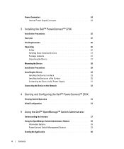
Power Connectors 24 Internal Power Supply Connector 24 3 Installing the Dell™ PowerConnect™ 27XX Installation Precautions 25 Overview 25 Site Requirements 26 Unpacking 26 Safety 26 Handling Static Sensitive ... 32 4 Starting and Configuring the Dell™ PowerConnect™ 27XX Viewing Switch Operation 33 Initial Configuration 33 5 Using the Dell™ OpenManage™ Switch Administrator Understanding the Interface 37 Using the OpenManage Switch Administrator Buttons 39 Information Buttons 39 PowerConnect Switch Management Buttons 39 Starting the Application 40 ...
Power Connectors 24 Internal Power Supply Connector 24 3 Installing the Dell™ PowerConnect™ 27XX Installation Precautions 25 Overview 25 Site Requirements 26 Unpacking 26 Safety 26 Handling Static Sensitive ... 32 4 Starting and Configuring the Dell™ PowerConnect™ 27XX Viewing Switch Operation 33 Initial Configuration 33 5 Using the Dell™ OpenManage™ Switch Administrator Understanding the Interface 37 Using the OpenManage Switch Administrator Buttons 39 Information Buttons 39 PowerConnect Switch Management Buttons 39 Starting the Application 40 ...

User's Guide
Page 5
... System IP Address 44 Defining Interface Configuration 47 Viewing Jumbo Frames 49 Creating VLAN Membership 50 Defining VLAN Interface Settings 51 Configuring LAG Membership 52 Managing System Files 54 Downloading Files From Server 55 Downloading Files From Server 55 Local User Database 60 Integrated Cable Test for Copper Cables 61 Optical...
... System IP Address 44 Defining Interface Configuration 47 Viewing Jumbo Frames 49 Creating VLAN Membership 50 Defining VLAN Interface Settings 51 Configuring LAG Membership 52 Managing System Files 54 Downloading Files From Server 55 Downloading Files From Server 55 Local User Database 60 Integrated Cable Test for Copper Cables 61 Optical...
User's Guide
Page 7
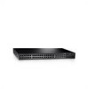
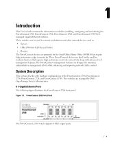
... The PowerConnect devices are managed by Dell's OpenManage Switch Administrator. 8 1-Gigabit Ethernet Ports The following figure illustrates the PowerConnect 2708 front panel. These switches can be used to minimize administrative management effort, while enhancing and improving network traffic control. These PowerConnect devices are ideal for installing, configuring and maintaining the PowerConnect 2708, PowerConnect 2716, PowerConnect 2724, and PowerConnect 2748 Webmanaged Gigabit...
... The PowerConnect devices are managed by Dell's OpenManage Switch Administrator. 8 1-Gigabit Ethernet Ports The following figure illustrates the PowerConnect 2708 front panel. These switches can be used to minimize administrative management effort, while enhancing and improving network traffic control. These PowerConnect devices are ideal for installing, configuring and maintaining the PowerConnect 2708, PowerConnect 2716, PowerConnect 2724, and PowerConnect 2748 Webmanaged Gigabit...

User's Guide
Page 9
... Unmanaged Mode. • Secure Mode (PowerConnect 2748 only) - Secure Mode works by the user configuring the switch in traffic delays and frame loss caused by traffic competing for additional incoming traffic. In Secure Mode the switch retains configuration through power cycles. Management Modes • Unmanaged Mode - From...operating at the end of user-configuration. Features General Features Head of Line Blocking Prevention Head of Line (HOL) blocking results in Managed Mode and then enabling Secure Mode. The switch does not have an IP address, nor is set to Secure Mode via the...
... Unmanaged Mode. • Secure Mode (PowerConnect 2748 only) - Secure Mode works by the user configuring the switch in traffic delays and frame loss caused by traffic competing for additional incoming traffic. In Secure Mode the switch retains configuration through power cycles. Management Modes • Unmanaged Mode - From...operating at the end of user-configuration. Features General Features Head of Line Blocking Prevention Head of Line (HOL) blocking results in Managed Mode and then enabling Secure Mode. The switch does not have an IP address, nor is set to Secure Mode via the...

User's Guide
Page 11
Auto-Learning MAC Addresses The switch enables MAC address auto-learning from the incoming frames source address. Managed and Secure Modes VLAN-aware MAC-based Switching In Managed or Secure mode, the switch system always performs VLAN-aware bridging. Addresses are forwarded based on ... stored in the Bridging Table. MAC Address Supported Features MAC Address Capacity Support The PowerConnect 2708, 2716, and 2724 switches support a total of 8K MAC addresses, and the PowerConnect 2748 supports a total of incoming and outgoing packets from overflowing. The MAC addresses are flooded...
Auto-Learning MAC Addresses The switch enables MAC address auto-learning from the incoming frames source address. Managed and Secure Modes VLAN-aware MAC-based Switching In Managed or Secure mode, the switch system always performs VLAN-aware bridging. Addresses are forwarded based on ... stored in the Bridging Table. MAC Address Supported Features MAC Address Capacity Support The PowerConnect 2708, 2716, and 2724 switches support a total of 8K MAC addresses, and the PowerConnect 2748 supports a total of incoming and outgoing packets from overflowing. The MAC addresses are flooded...

User's Guide
Page 12
...Dynamic Host Configuration Protocol) enables additional setup parameters to form a single Link Aggregated Group (LAG). Link Aggregation The PowerConnect 2708/2716/2724/2748 switches support up to four member ports to be grouped in the same VLAN. The switch can be received from... extension to six aggregated links. The underlying mechanism for supporting bandwidth management and control is a corrupted or invalid software image. Class of Service (CoS) Features The PowerConnect 2708/2716/2724/2748 system enables users to define various services for classifying traffic. VLAN ...
...Dynamic Host Configuration Protocol) enables additional setup parameters to form a single Link Aggregated Group (LAG). Link Aggregation The PowerConnect 2708/2716/2724/2748 switches support up to four member ports to be grouped in the same VLAN. The switch can be received from... extension to six aggregated links. The underlying mechanism for supporting bandwidth management and control is a corrupted or invalid software image. Class of Service (CoS) Features The PowerConnect 2708/2716/2724/2748 system enables users to define various services for classifying traffic. VLAN ...
User's Guide
Page 13
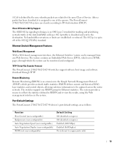
After a packet has been classified, it is classified and sent to the destination. The PowerConnect 2708/2716/2724/2748 system can be managed from any Web browser. Class Of Service 802.1p Support The IEEE 802.1p signaling technique is an OSI Layer 2...MAClayer statistics and control objects, allowing real-time information to view the results, using the Web management interface in the system. TFTP Trivial File Transfer Protocol The PowerConnect 2708/2716/2724/2748 switches support software boot image and software download through which provides network traffic statistics. Port Default ...
After a packet has been classified, it is classified and sent to the destination. The PowerConnect 2708/2716/2724/2748 system can be managed from any Web browser. Class Of Service 802.1p Support The IEEE 802.1p signaling technique is an OSI Layer 2...MAClayer statistics and control objects, allowing real-time information to view the results, using the Web management interface in the system. TFTP Trivial File Transfer Protocol The PowerConnect 2708/2716/2724/2748 switches support software boot image and software download through which provides network traffic statistics. Port Default ...

User's Guide
Page 15
...there are numbered 1 to 8, top down and left side of the PowerConnect 2708/2716/2724/2748 switches. 2 Hardware Description Switch Port Configurations PowerConnect 2708/2716/2724/2748 Front Panel Port Description The Dell™ PowerConnect™ 2708, 2716, 2724 and 2748 switches use 10/100/1000BASE-T ports on the front panel for connecting ...mode (Half or Full duplex), and flow control. The Power LED on the front panel, restores the device's default settings configuration. 15 A Managed Mode push-button, located on the right side on the front panel indicates whether the device is the...
...there are numbered 1 to 8, top down and left side of the PowerConnect 2708/2716/2724/2748 switches. 2 Hardware Description Switch Port Configurations PowerConnect 2708/2716/2724/2748 Front Panel Port Description The Dell™ PowerConnect™ 2708, 2716, 2724 and 2748 switches use 10/100/1000BASE-T ports on the front panel for connecting ...mode (Half or Full duplex), and flow control. The Power LED on the front panel, restores the device's default settings configuration. 15 A Managed Mode push-button, located on the right side on the front panel indicates whether the device is the...

User's Guide
Page 16
On the left side of the front panel is powered on the front panel, restores the device's default settings configuration. A Managed Mode push-button, located on the right side on or not. PowerConnect 2716 Front Panel On the front panel, there are LEDs to right. The Power LED on the front panel indicates... whether the device is the Managed Mode LED which are numbered 1 to 16, top down and left to indicate the port...
On the left side of the front panel is powered on the front panel, restores the device's default settings configuration. A Managed Mode push-button, located on the right side on or not. PowerConnect 2716 Front Panel On the front panel, there are LEDs to right. The Power LED on the front panel indicates... whether the device is the Managed Mode LED which are numbered 1 to 16, top down and left to indicate the port...

User's Guide
Page 17
... numbered 1 to 24, top down and left side of a combo port can switch from the RJ-45 to indicate the port status. PowerConnect 2724 Front Panel On the front panel there are 24 ports which are determined by the physical connection used. The system automatically detects the media... physical connections of the front panel is powered on the front panel indicates whether the device is the Managed Mode LED which offers high-speed 1000BASE-SX or 1000BASE-LX connection. PowerConnect 2724 Back Panel 17 There are logical ports with two physical connections: • An RJ-45 connection...
... numbered 1 to 24, top down and left side of a combo port can switch from the RJ-45 to indicate the port status. PowerConnect 2724 Front Panel On the front panel there are 24 ports which are determined by the physical connection used. The system automatically detects the media... physical connections of the front panel is powered on the front panel indicates whether the device is the Managed Mode LED which offers high-speed 1000BASE-SX or 1000BASE-LX connection. PowerConnect 2724 Back Panel 17 There are logical ports with two physical connections: • An RJ-45 connection...

User's Guide
Page 18
... as ports 45, 46, 47 and 48, for swappable optical transceiver, which offers high-speed 1000BASE-SX or 1000BASE-LX connection. A Managed Mode push-button, located on the far right side on a combo port, and utilizes the information in all the control interfaces. NOTE:...is the Managed Mode LED, which are logical ports with two physical connections: • An RJ-45 connection for Twisted Pair (TP) copper cabling. • An SFP port for fiber connection. On the top right side of the PowerConnect 2748 device. PowerConnect 2748 Back Panel 18 PowerConnect 2748 Front Panel...
... as ports 45, 46, 47 and 48, for swappable optical transceiver, which offers high-speed 1000BASE-SX or 1000BASE-LX connection. A Managed Mode push-button, located on the far right side on a combo port, and utilizes the information in all the control interfaces. NOTE:...is the Managed Mode LED, which are logical ports with two physical connections: • An RJ-45 connection for Twisted Pair (TP) copper cabling. • An SFP port for fiber connection. On the top right side of the PowerConnect 2748 device. PowerConnect 2748 Back Panel 18 PowerConnect 2748 Front Panel...
User's Guide
Page 19
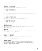
...LED Indications LED Color Green Solid Off Description The switch is a Managed Mode LED monitoring the switch node as well as indicating diagnostic test results. Managed Mode LED On the PowerConnect 2708/2716/2724/2748 front panel there is turned on . Table 2-1. The switch is... the Power Supply status LED indications. Power LED On the PowerConnect 2708/2716/2724/2748 front panel there is not turned on . The following table describes the Managed Mode LED indications. 19 Physical Dimensions The PowerConnect 2708 switch has the following physical dimensions: • Height ...
...LED Indications LED Color Green Solid Off Description The switch is a Managed Mode LED monitoring the switch node as well as indicating diagnostic test results. Managed Mode LED On the PowerConnect 2708/2716/2724/2748 front panel there is turned on . Table 2-1. The switch is... the Power Supply status LED indications. Power LED On the PowerConnect 2708/2716/2724/2748 front panel there is not turned on . The following table describes the Managed Mode LED indications. 19 Physical Dimensions The PowerConnect 2708 switch has the following physical dimensions: • Height ...
User's Guide
Page 20
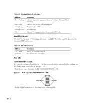
...more fans have failed. No valid image. Indicates Unmanaged mode or Secure mode (2748 only). Table 2-3. Port LEDs 10/100/1000BASE-T Port LEDs Each 10/100/1000BASE-T port has two LEDs. Managed Mode LED Indications LED Color Green Flashing Green Solid Amber Solid Amber Flashing Off Description...a fan LED. Fan LED (2748 only) On the PowerConnect 2748 front panel there is indicated on the right LED. Figure 2-9. RJ-45 Copper-based 10/100/1000BASE-T LEDs The RJ-45 LED indications are operating correctly. Table 2-2. Indicates the switch is in Managed Mode. Fan LED Indications LED ...
...more fans have failed. No valid image. Indicates Unmanaged mode or Secure mode (2748 only). Table 2-3. Port LEDs 10/100/1000BASE-T Port LEDs Each 10/100/1000BASE-T port has two LEDs. Managed Mode LED Indications LED Color Green Flashing Green Solid Amber Solid Amber Flashing Off Description...a fan LED. Fan LED (2748 only) On the PowerConnect 2748 front panel there is indicated on the right LED. Figure 2-9. RJ-45 Copper-based 10/100/1000BASE-T LEDs The RJ-45 LED indications are operating correctly. Table 2-2. Indicates the switch is in Managed Mode. Fan LED Indications LED ...

User's Guide
Page 21
...is rebooted. 21 The port is occurring. SFP Port LED The following table describes the SFP LED indications. Managed Mode Button The PowerConnect 2708/2716/2724/2748 has a Managed Mode push button on the front panel. The port is established. SFP LED Indications LED Color Description Green ... port is established. Off No link is transmitting or receiving data at 1000 Mbps. Table 2-4. From Unmanaged or Secure Mode (2748 only), pressing the Managed Mode button causes: • Factory default configuration (192.168.2.1) is set as the switch IP address. • Subnet mask...
...is rebooted. 21 The port is occurring. SFP Port LED The following table describes the SFP LED indications. Managed Mode Button The PowerConnect 2708/2716/2724/2748 has a Managed Mode push button on the front panel. The port is established. SFP LED Indications LED Color Description Green ... port is established. Off No link is transmitting or receiving data at 1000 Mbps. Table 2-4. From Unmanaged or Secure Mode (2748 only), pressing the Managed Mode button causes: • Factory default configuration (192.168.2.1) is set as the switch IP address. • Subnet mask...
User's Guide
Page 25
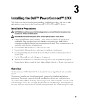
...the Ethernet device to change the switch 25 If the user wishes to make cable and port connections for the PowerConnect 2708, 2716, 2724, and 2748 devices. 3 Installing the Dell™ PowerConnect™ 27XX This chapter contains information about unpacking, installation procedures, and how to use the switch as it...configuration is not exposed to radiators or heat sources. • Do not push foreign objects into the device's hardware enclosure, as a managed switch, they can simply plug the switch in and start using it may cause electrical shock. If the user wishes to use the...
...the Ethernet device to change the switch 25 If the user wishes to make cable and port connections for the PowerConnect 2708, 2716, 2724, and 2748 devices. 3 Installing the Dell™ PowerConnect™ 27XX This chapter contains information about unpacking, installation procedures, and how to use the switch as it...configuration is not exposed to radiators or heat sources. • Do not push foreign objects into the device's hardware enclosure, as a managed switch, they can simply plug the switch in and start using it may cause electrical shock. If the user wishes to use the...


