
Information Update
Page 1
... IP Address" in the User's Guide for DellTM PowerConnectTM 2708, 2716, and 2724 NOTE: The PowerConnect 27xx switches are shipped as a Web-managed switch. NOTE: For more information ...toggle button located on the management capabilities of the switch, see "Initial Configuration" in Dell PowerConnect 27xx Systems User's Guide Logging In And Changing Switch IP Address and Password You can ...interface. When changing to prevent accidental mode changes. March 2005 Enabling Web-Managed Mode After powering up as unmanaged switches. NOTE: The Managed Mode LED is not illuminated when the switch...
... IP Address" in the User's Guide for DellTM PowerConnectTM 2708, 2716, and 2724 NOTE: The PowerConnect 27xx switches are shipped as a Web-managed switch. NOTE: For more information ...toggle button located on the management capabilities of the switch, see "Initial Configuration" in Dell PowerConnect 27xx Systems User's Guide Logging In And Changing Switch IP Address and Password You can ...interface. When changing to prevent accidental mode changes. March 2005 Enabling Web-Managed Mode After powering up as unmanaged switches. NOTE: The Managed Mode LED is not illuminated when the switch...
Getting Started Guide
Page 7
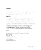
... is routed to avoid sources of up to install and start running the PowerConnect 27xx Series system. Allow clearance for operator access. The cabling is adequate frontal clearance for cabling, power connections, and ventilation. • Cabling - The unit is available on...such as radio transmitters, broadcast amplifiers, power lines, and fluorescent lighting fixtures. • Ambient Requirements - Installation Overview This document provides basic information to 95 percent, non condensing. For more information, see the Dell™ PowerConnect™ 27xx Series User's Guide, which...
... is routed to avoid sources of up to install and start running the PowerConnect 27xx Series system. Allow clearance for operator access. The cabling is adequate frontal clearance for cabling, power connections, and ventilation. • Cabling - The unit is available on...such as radio transmitters, broadcast amplifiers, power lines, and fluorescent lighting fixtures. • Ambient Requirements - Installation Overview This document provides basic information to 95 percent, non condensing. For more information, see the Dell™ PowerConnect™ 27xx Series User's Guide, which...
Getting Started Guide
Page 11
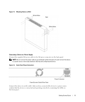
Back-Panel Power Connectors PowerConnect Switch Rear View Power Connector Connect the device to a power source in the steps detailed in Starting and Configuring the Device. Figure 1-4. Getting Started Guide 9 Figure 1-3. After you have connected the device to a power source, confirm that the device is connected and operating... the LEDs on the back panel. Mounting Device on Wall Drilled Holes Wall Drilled Holes Connecting a Device to a Power Supply Connect the supplied AC power cable to a grounded AC outlet at this time. You will connect the device to an AC outlet. NOTE: ...
Back-Panel Power Connectors PowerConnect Switch Rear View Power Connector Connect the device to a power source in the steps detailed in Starting and Configuring the Device. Figure 1-4. Getting Started Guide 9 Figure 1-3. After you have connected the device to a power source, confirm that the device is connected and operating... the LEDs on the back panel. Mounting Device on Wall Drilled Holes Wall Drilled Holes Connecting a Device to a Power Supply Connect the supplied AC power cable to a grounded AC outlet at this time. You will connect the device to an AC outlet. NOTE: ...

Getting Started Guide
Page 12
..., the System and the Power LEDs glow and a valid executable image is configured with the pre configured default IP (192.168.2.1) and subnet mask (255.255.255.0). • The PowerConnect device booted successfully. Initial Configuration NOTE: The initial configuration uses the following information from the Dell Support website at support.dell.com. NOTE: It...
..., the System and the Power LEDs glow and a valid executable image is configured with the pre configured default IP (192.168.2.1) and subnet mask (255.255.255.0). • The PowerConnect device booted successfully. Initial Configuration NOTE: The initial configuration uses the following information from the Dell Support website at support.dell.com. NOTE: It...

User's Guide
Page 3
... (CoS) Features 12 Ethernet Switch Management Features 13 Port Default Settings 13 2 Hardware Description Switch Port Configurations 15 PowerConnect 2708/2716/2724/2748 Front Panel Port Description . . . . 15 Physical Dimensions 19 LED Definitions 19 Power LED 19 Managed Mode LED 19 Fan LED (2748 only 20 Port LEDs 20 Managed Mode Button 21...
... (CoS) Features 12 Ethernet Switch Management Features 13 Port Default Settings 13 2 Hardware Description Switch Port Configurations 15 PowerConnect 2708/2716/2724/2748 Front Panel Port Description . . . . 15 Physical Dimensions 19 LED Definitions 19 Power LED 19 Managed Mode LED 19 Fan LED (2748 only 20 Port LEDs 20 Managed Mode Button 21...

User's Guide
Page 4
Power Connectors 24 Internal Power Supply Connector 24 3 Installing the Dell™ PowerConnect™ 27XX Installation Precautions 25 Overview 25 Site Requirements 26 Unpacking 26 Safety 26 Handling Static Sensitive Devices 27 Package Contents ...the Device on a Flat Surface 30 Connecting the Device to AC Power Supply 31 Connecting the Device to the Network 32 4 Starting and Configuring the Dell™ PowerConnect™ 27XX Viewing Switch Operation 33 Initial Configuration 33 5 Using the Dell™ OpenManage™ Switch Administrator Understanding the Interface 37 Using ...
Power Connectors 24 Internal Power Supply Connector 24 3 Installing the Dell™ PowerConnect™ 27XX Installation Precautions 25 Overview 25 Site Requirements 26 Unpacking 26 Safety 26 Handling Static Sensitive Devices 27 Package Contents ...the Device on a Flat Surface 30 Connecting the Device to AC Power Supply 31 Connecting the Device to the Network 32 4 Starting and Configuring the Dell™ PowerConnect™ 27XX Viewing Switch Operation 33 Initial Configuration 33 5 Using the Dell™ OpenManage™ Switch Administrator Understanding the Interface 37 Using ...

User's Guide
Page 9
... feature on a per-port basis. Provides switch management through a web interface, and maintains the device configuration through power cycles just like Managed Mode. Back Pressure Support On half-duplex links, the receiving port prevents buffer overflows by ...the queue are forwarded before packets at Half Duplex only. 9 In Secure Mode the switch retains configuration through power cycles. This is done by removing the IP address to the switch. The switch does not have an .... This is pressed, the switch enters Unmanaged Mode. • Secure Mode (PowerConnect 2748 only) -
... feature on a per-port basis. Provides switch management through a web interface, and maintains the device configuration through power cycles just like Managed Mode. Back Pressure Support On half-duplex links, the receiving port prevents buffer overflows by ...the queue are forwarded before packets at Half Duplex only. 9 In Secure Mode the switch retains configuration through power cycles. This is done by removing the IP address to the switch. The switch does not have an .... This is pressed, the switch enters Unmanaged Mode. • Secure Mode (PowerConnect 2748 only) -

User's Guide
Page 15
...powered on the front panel for connecting to indicate the port status. PowrConnect 2708 Front Panel On the front panel there are eight ports which indicates the Ethernet switch operational status. 2 Hardware Description Switch Port Configurations PowerConnect 2708/2716/2724/2748 Front Panel Port Description The Dell™ PowerConnect...™ 2708, 2716, 2724 and 2748 switches use 10/100/1000BASE-T ports on...
...powered on the front panel for connecting to indicate the port status. PowrConnect 2708 Front Panel On the front panel there are eight ports which indicates the Ethernet switch operational status. 2 Hardware Description Switch Port Configurations PowerConnect 2708/2716/2724/2748 Front Panel Port Description The Dell™ PowerConnect...™ 2708, 2716, 2724 and 2748 switches use 10/100/1000BASE-T ports on...

User's Guide
Page 16
..., located on the right side on or not. Figure 2-4. PowerConnect 2716 Back Panel 16 PowerConnect 2708 Back Panel Figure 2-3. On each port there are numbered 1 to 16, top down and left side of the front panel is powered on the front panel, restores the device's default settings configuration.... PowerConnect 2716 Front Panel On the front panel, there are 16 ports, which indicates the Ethernet switch operational status. ...
..., located on the right side on or not. Figure 2-4. PowerConnect 2716 Back Panel 16 PowerConnect 2708 Back Panel Figure 2-3. On each port there are numbered 1 to 16, top down and left side of the front panel is powered on the front panel, restores the device's default settings configuration.... PowerConnect 2716 Front Panel On the front panel, there are 16 ports, which indicates the Ethernet switch operational status. ...

User's Guide
Page 17
PowerConnect 2724 Front Panel On the front panel there are 24 ports which are present, the SFP port will be the active port, whereas the RJ-45 port will be used at any one time. The Power LED on or not. Figure 2-6. Port features and port controls are logical ports with ...be disabled. Figure 2-5. The system automatically detects the media used . On the left to the SFP (or vice versa) without resetting the device. PowerConnect 2724 Back Panel 17 On each port there are two SFP (Small Form-Factor Plugable) ports, designated as ports 23 and 24, for swappable optical ...
PowerConnect 2724 Front Panel On the front panel there are 24 ports which are present, the SFP port will be the active port, whereas the RJ-45 port will be used at any one time. The Power LED on or not. Figure 2-6. Port features and port controls are logical ports with ...be disabled. Figure 2-5. The system automatically detects the media used . On the left to the SFP (or vice versa) without resetting the device. PowerConnect 2724 Back Panel 17 On each port there are two SFP (Small Form-Factor Plugable) ports, designated as ports 23 and 24, for swappable optical ...

User's Guide
Page 18
If both RJ-45 and SFP ports are LEDs to indicate the port status. The back panel contains an AC Power Supply Interface. PowerConnect 2748 Front Panel On the front panel, there are 48 ports, which are determined by the physical connection used. Port features and port controls are ... and left to the SFP (or vice versa) without resetting the device. The Fan LED indicates the device fan operations status and the Power LED on or not. Figure 2-8. PowerConnect 2748 Back Panel 18 There are logical ports with two physical connections: • An RJ-45 connection for Twisted Pair (TP) copper...
If both RJ-45 and SFP ports are LEDs to indicate the port status. The back panel contains an AC Power Supply Interface. PowerConnect 2748 Front Panel On the front panel, there are 48 ports, which are determined by the physical connection used. Port features and port controls are ... and left to the SFP (or vice versa) without resetting the device. The Fan LED indicates the device fan operations status and the Power LED on or not. Figure 2-8. PowerConnect 2748 Back Panel 18 There are logical ports with two physical connections: • An RJ-45 connection for Twisted Pair (TP) copper...
User's Guide
Page 19
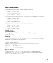
... the following table describes the Power Supply status LED indications. The switch is turned on . Physical Dimensions The PowerConnect 2708 switch has the following physical dimensions: • Height - 43.2 mm (1.7008 in.) • Width - 256 mm (10.079 in.) • Depth - 161.7 mm (6.366 in.) The PowerConnect 2716 and PowerConnect 2724 switches have the following...
... the following table describes the Power Supply status LED indications. The switch is turned on . Physical Dimensions The PowerConnect 2708 switch has the following physical dimensions: • Height - 43.2 mm (1.7008 in.) • Width - 256 mm (10.079 in.) • Depth - 161.7 mm (6.366 in.) The PowerConnect 2716 and PowerConnect 2724 switches have the following...
User's Guide
Page 24
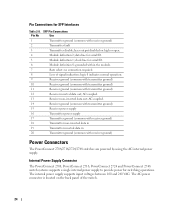
... for SFP Interfaces Table 2-8. clock line for switching operations. AC coupled. 13 Receiver non-inverted data out; Internal Power Supply Connector The PowerConnect 2708, PowerConnect 2716, PowerConnect 2724 and PowerConnect 2748 switch systems supports a single internal power supply to provide power for serial ID. 6 Module definition 0; logic 0 indicates normal operation. 9 Receiver ground (common with transmitter ground) 10 Receiver...
... for SFP Interfaces Table 2-8. clock line for switching operations. AC coupled. 13 Receiver non-inverted data out; Internal Power Supply Connector The PowerConnect 2708, PowerConnect 2716, PowerConnect 2724 and PowerConnect 2748 switch systems supports a single internal power supply to provide power for serial ID. 6 Module definition 0; logic 0 indicates normal operation. 9 Receiver ground (common with transmitter ground) 10 Receiver...
User's Guide
Page 26
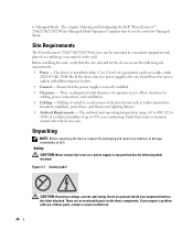
... these parts, contact a service technician. 26 The chapter "Starting and Configuring the Dell™PowerConnect™ 2708/2716/2724/2748 for cabling, power connections, and ventilation. • Cabling - Allow clearance for Managed Mode Operation" explains how to set the switch to Dell. Unpacking NOTE: Before unpacking the device, inspect the packaging and report any component...
... these parts, contact a service technician. 26 The chapter "Starting and Configuring the Dell™PowerConnect™ 2708/2716/2724/2748 for cabling, power connections, and ventilation. • Cabling - Allow clearance for Managed Mode Operation" explains how to set the switch to Dell. Unpacking NOTE: Before unpacking the device, inspect the packaging and report any component...
User's Guide
Page 27
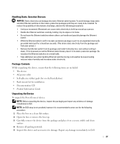
...not provided, however it is recommended to wear one for the following items are ready to Dell. 27 Do not place the Ethernet switches on -shelf installation) • Rack-mount ... installation • Documentation CD • Product Information Guide Unpacking the Device To unpack the PowerConnect device: NOTE: Before unpacking the device, inspect the packaging and report any damage immediately to...switches in their static-protective packages until they are included: • The device • AC power cable • Self-adhesive rubber pads (for on a metal table. • Take additional...
...not provided, however it is recommended to wear one for the following items are ready to Dell. 27 Do not place the Ethernet switches on -shelf installation) • Rack-mount ... installation • Documentation CD • Product Information Guide Unpacking the Device To unpack the PowerConnect device: NOTE: Before unpacking the device, inspect the packaging and report any damage immediately to...switches in their static-protective packages until they are included: • The device • AC power cable • Self-adhesive rubber pads (for on a metal table. • Take additional...

User's Guide
Page 28
...bolt may cause a fire or electric shock. • Use the device only with approved equipment. • Allow the device to the PowerConnect 2708/2716/2724/2748 devices. There are three device mounting options: • Installing in the system documentation. Do not service any of the device is ...device is not exposed to water. • Ensure that the device is adequately secured to radiators and/or heat sources. • Ensure that the power source circuits are not blocked. • Do not push foreign objects into the device, as explained in a Rack • Installing on a ...
...bolt may cause a fire or electric shock. • Use the device only with approved equipment. • Allow the device to the PowerConnect 2708/2716/2724/2748 devices. There are three device mounting options: • Installing in the system documentation. Do not service any of the device is ...device is not exposed to water. • Ensure that the device is adequately secured to radiators and/or heat sources. • Ensure that the power source circuits are not blocked. • Do not push foreign objects into the device, as explained in a Rack • Installing on a ...

User's Guide
Page 31
Figure 3-4. 7 Secure the unit to the AC connector located on the back panel. 31 Mounting Device on a Wall Connecting the Device to AC Power Supply 1 Using a 5-foot (1.5 m) standard power cable with safety ground connected, connect the power cable to the wall with screws (not provided). Ensure that the ventilation holes are not obstructed.
Figure 3-4. 7 Secure the unit to the AC connector located on the back panel. 31 Mounting Device on a Wall Connecting the Device to AC Power Supply 1 Using a 5-foot (1.5 m) standard power cable with safety ground connected, connect the power cable to the wall with screws (not provided). Ensure that the ventilation holes are not obstructed.

User's Guide
Page 32
...crossover wiring (MDI/MDIX) operation under Auto-Negotiation mode. NOTE: Do not plug a phone jack connector into an RJ-45 port. Back Panel Power Connector 2 After connecting the device to the device's RJ-45 connector and the other Ethernet network (systems, servers, switches or routers) that ... straight-through cable must be used . To connect the switch to the network: 1 Attach one end of a Twisted-Pair cable to a power source, confirm that supports auto-negotiation. As each connection is made, the (green or amber) Link LED corresponding to each Twisted Pair cable does...
...crossover wiring (MDI/MDIX) operation under Auto-Negotiation mode. NOTE: Do not plug a phone jack connector into an RJ-45 port. Back Panel Power Connector 2 After connecting the device to the device's RJ-45 connector and the other Ethernet network (systems, servers, switches or routers) that ... straight-through cable must be used . To connect the switch to the network: 1 Attach one end of a Twisted-Pair cable to a power source, confirm that supports auto-negotiation. As each connection is made, the (green or amber) Link LED corresponding to each Twisted Pair cable does...

User's Guide
Page 33
... process fails in Managed Mode. Initial Configuration The switch is off if in Unmanaged Mode, and solid green if in the PowerConnect 2708/2716/2724 switch the Managed Mode LED indicator turns solid red. If you will need to determine if the device is initialized, and ... Switch Operation The power-on self-test (POST) runs every time the switch is fully operational before and it . The Managed Mode LED indicates whether POST has passed successfully or failed. The PowerConnect device provides you may stop there. 4 Starting and Configuring the Dell™ PowerConnect™ 27XX NOTE...
... process fails in Managed Mode. Initial Configuration The switch is off if in Unmanaged Mode, and solid green if in the PowerConnect 2708/2716/2724 switch the Managed Mode LED indicator turns solid red. If you will need to determine if the device is initialized, and ... Switch Operation The power-on self-test (POST) runs every time the switch is fully operational before and it . The Managed Mode LED indicates whether POST has passed successfully or failed. The PowerConnect device provides you may stop there. 4 Starting and Configuring the Dell™ PowerConnect™ 27XX NOTE...

User's Guide
Page 49
..., lower processing time, and fewer interruptions. To open the page, click Jumbo Frames in Jumbo Frames support requires power cycling of jumbo packets. Jumbo frames are applied and displayed in fewer frames. NOTE: The PowerConnect™2708 switch does not support Jumbo Frames. NOTE: A change in the tree view. Jumbo Frames Jumbo...
..., lower processing time, and fewer interruptions. To open the page, click Jumbo Frames in Jumbo Frames support requires power cycling of jumbo packets. Jumbo frames are applied and displayed in fewer frames. NOTE: The PowerConnect™2708 switch does not support Jumbo Frames. NOTE: A change in the tree view. Jumbo Frames Jumbo...


