
Information Update
Page 1
... in unmanaged mode. In this switch, follow the steps in Dell PowerConnect 27xx Systems User's Guide. NOTE: The Managed Mode LED is not illuminated when the switch is configured with a default IP address (192.168.2.1) and a default user login (User Name: admin and no password). NOTE: For..."Viewing System IP Address" in the User's Guide for DellTM PowerConnectTM 2708, 2716, and 2724 NOTE: The PowerConnect 27xx switches are shipped as a Web-managed switch. www.dell.com | support.dell.com Enabling Web-Managed Mode for changing the password. NOTE: When changing between the unmanaged...
... in unmanaged mode. In this switch, follow the steps in Dell PowerConnect 27xx Systems User's Guide. NOTE: The Managed Mode LED is not illuminated when the switch is configured with a default IP address (192.168.2.1) and a default user login (User Name: admin and no password). NOTE: For..."Viewing System IP Address" in the User's Guide for DellTM PowerConnectTM 2708, 2716, and 2724 NOTE: The PowerConnect 27xx switches are shipped as a Web-managed switch. www.dell.com | support.dell.com Enabling Web-Managed Mode for changing the password. NOTE: When changing between the unmanaged...
Information Update
Page 2
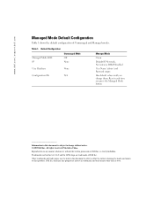
... disclaims any manner whatsoever without notice. © 2005 Dell Inc. All rights reserved. Trademarks used in this document to refer to change them; Dell Inc. Printed in this document is strictly forbidden. Default Configuration Managed Mode LED IP Unmanaged Mode Off None User...Other trademarks and trade names may be used in this text: Dell and the DELL logo are trademarks of Dell Inc. www.dell.com | support.dell.com Managed Mode Default Configuration Table 1 shows the default configuration of Dell Inc. Table 1. Resets each time you change without the written ...
... disclaims any manner whatsoever without notice. © 2005 Dell Inc. All rights reserved. Trademarks used in this document to refer to change them; Dell Inc. Printed in this document is strictly forbidden. Default Configuration Managed Mode LED IP Unmanaged Mode Off None User...Other trademarks and trade names may be used in this text: Dell and the DELL logo are trademarks of Dell Inc. www.dell.com | support.dell.com Managed Mode Default Configuration Table 1 shows the default configuration of Dell Inc. Table 1. Resets each time you change without the written ...

Getting Started Guide
Page 12
...'s Guide. NOTE: Before proceeding, read the release notes for configuring the default route. 10 Getting Started Guide A power-on the enclosed CD. NOTE: Obtain the following assumptions: • The PowerConnect device is designed to function as an unmanaged switch without any configuration of ... the Dell Support website at support.dell.com. Booting the Switch When the device is to the device. Starting and Configuring the Device NOTE: The device is configured with the pre configured default IP (192.168.2.1) and subnet mask (255.255.255.0). • The PowerConnect device ...
...'s Guide. NOTE: Before proceeding, read the release notes for configuring the default route. 10 Getting Started Guide A power-on the enclosed CD. NOTE: Obtain the following assumptions: • The PowerConnect device is designed to function as an unmanaged switch without any configuration of ... the Dell Support website at support.dell.com. Booting the Switch When the device is to the device. Starting and Configuring the Device NOTE: The device is configured with the pre configured default IP (192.168.2.1) and subnet mask (255.255.255.0). • The PowerConnect device ...

Getting Started Guide
Page 13
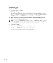
... Mozilla Version 1.7.x or above. 2 In the Web user interface, Click IP Addressing. For more information on the management capabilities of the switch, please refer the PowerConnect 27xx Series User's Guide found on the steps necessary for basic setup of a web browser. The System IP Address window appears. 3 Enter the IP Address...
... Mozilla Version 1.7.x or above. 2 In the Web user interface, Click IP Addressing. For more information on the management capabilities of the switch, please refer the PowerConnect 27xx Series User's Guide found on the steps necessary for basic setup of a web browser. The System IP Address window appears. 3 Enter the IP Address...
Readme
Page 4
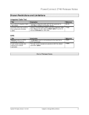
...accepts any password for default username Description The Browse button is not mentioned in the help file for HTTP downloads in help file. Reference 72487 71825 End of Release Notes System Firmware Version 1.0.0.32 Subject to 1000 Mbps, displays inconsistent results. PowerConnect 2748 Release Notes ... as Short Cable for ports G1G44 and Unknown for the combo ports (shorted cable) Description Testing the integrated cable with the default username, admin. Login screen accepts any password with the link speed set to Change Without Notice 2 Reference 69139 71496 EWS Title...
...accepts any password for default username Description The Browse button is not mentioned in the help file for HTTP downloads in help file. Reference 72487 71825 End of Release Notes System Firmware Version 1.0.0.32 Subject to 1000 Mbps, displays inconsistent results. PowerConnect 2748 Release Notes ... as Short Cable for ports G1G44 and Unknown for the combo ports (shorted cable) Description Testing the integrated cable with the default username, admin. Login screen accepts any password with the link speed set to Change Without Notice 2 Reference 69139 71496 EWS Title...

User's Guide
Page 3
... 11 Layer 2 Features 11 VLAN Supported Features 12 Class of Service (CoS) Features 12 Ethernet Switch Management Features 13 Port Default Settings 13 2 Hardware Description Switch Port Configurations 15 PowerConnect 2708/2716/2724/2748 Front Panel Port Description . . . . 15 Physical Dimensions 19 LED Definitions 19 Power LED 19 Managed Mode LED 19 Fan...
... 11 Layer 2 Features 11 VLAN Supported Features 12 Class of Service (CoS) Features 12 Ethernet Switch Management Features 13 Port Default Settings 13 2 Hardware Description Switch Port Configurations 15 PowerConnect 2708/2716/2724/2748 Front Panel Port Description . . . . 15 Physical Dimensions 19 LED Definitions 19 Power LED 19 Managed Mode LED 19 Fan...

User's Guide
Page 9
...the end of 192.168.2.1. The switch does not have an IP address, nor is pressed, the switch enters Unmanaged Mode. • Secure Mode (PowerConnect 2748 only) - To use Secure Mode, the user puts the switch in Managed Mode and then enabling Secure Mode. However, this feature on a per... is active at Half Duplex only. 9 From Unmanaged Mode, when the Managed Mode button is pressed, the switch enters Managed Mode with the default IP address of the queue. In Secure Mode the switch retains configuration through power cycles. Back Pressure Support On half-duplex links, the receiving ...
...the end of 192.168.2.1. The switch does not have an IP address, nor is pressed, the switch enters Unmanaged Mode. • Secure Mode (PowerConnect 2748 only) - To use Secure Mode, the user puts the switch in Managed Mode and then enabling Secure Mode. However, this feature on a per... is active at Half Duplex only. 9 From Unmanaged Mode, when the Managed Mode button is pressed, the switch enters Managed Mode with the default IP address of the queue. In Secure Mode the switch retains configuration through power cycles. Back Pressure Support On half-duplex links, the receiving ...

User's Guide
Page 12
...LAG is based on the use of multiple priority queues for traffic classes of service. Class of Service (CoS) Features The PowerConnect 2708/2716/2724/2748 system enables users to define various services for classifying traffic. The underlying mechanism for supporting bandwidth management and control is composed.... DHCP is an on-going process. Port Based Virtual LANs (VLANs) Port-based VLANs classify incoming packets to all ports on the default VLAN, until a BootP server replies. VLAN Supported Features VLAN Support VLANs are classified as belonging to a VLAN based on either the ...
...LAG is based on the use of multiple priority queues for traffic classes of service. Class of Service (CoS) Features The PowerConnect 2708/2716/2724/2748 system enables users to define various services for classifying traffic. The underlying mechanism for supporting bandwidth management and control is composed.... DHCP is an on-going process. Port Based Virtual LANs (VLANs) Port-based VLANs classify incoming packets to all ports on the default VLAN, until a BootP server replies. VLAN Supported Features VLAN Support VLANs are classified as belonging to a VLAN based on either the ...
User's Guide
Page 13
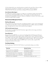
...standard for Ethernet statistics. The 802.1p is classified and sent to copper ports only) 13 Port Default Settings The PowerConnect 2708/2716/2724/2748 devices's port default settings are established or enforced. No bandwidth reservations or limits are as follows: Function Flow Control (...configurable) MDIX (not user-configurable) Default Setting Off (disabled on ingress) Off (disabled on ingress) Enabled (1000 Mbps) Enabled (Full Duplex) On (relevant to the destination. TFTP Trivial File Transfer Protocol The PowerConnect 2708/2716/2724/2748 switches support software boot image ...
...standard for Ethernet statistics. The 802.1p is classified and sent to copper ports only) 13 Port Default Settings The PowerConnect 2708/2716/2724/2748 devices's port default settings are established or enforced. No bandwidth reservations or limits are as follows: Function Flow Control (...configurable) MDIX (not user-configurable) Default Setting Off (disabled on ingress) Off (disabled on ingress) Enabled (1000 Mbps) Enabled (Full Duplex) On (relevant to the destination. TFTP Trivial File Transfer Protocol The PowerConnect 2708/2716/2724/2748 switches support software boot image ...

User's Guide
Page 15
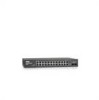
2 Hardware Description Switch Port Configurations PowerConnect 2708/2716/2724/2748 Front Panel Port Description The Dell™ PowerConnect™ 2708, 2716, 2724 and 2748 switches use 10/100/1000BASE-T ports on the front panel, restores the device's default settings configuration. 15 The following figures illustrate the front panels and...push-button, located on the right side on the front panel for connecting to 8, top down and left side of the PowerConnect 2708/2716/2724/2748 switches. The Gigabit Ethernet ports can only operate at 10, 100 or 1000 Mbps. On the left to indicate the...
2 Hardware Description Switch Port Configurations PowerConnect 2708/2716/2724/2748 Front Panel Port Description The Dell™ PowerConnect™ 2708, 2716, 2724 and 2748 switches use 10/100/1000BASE-T ports on the front panel, restores the device's default settings configuration. 15 The following figures illustrate the front panels and...push-button, located on the right side on the front panel for connecting to 8, top down and left side of the PowerConnect 2708/2716/2724/2748 switches. The Gigabit Ethernet ports can only operate at 10, 100 or 1000 Mbps. On the left to indicate the...

User's Guide
Page 16
...down and left side of the front panel is powered on or not. The Power LED on the front panel, restores the device's default settings configuration. A Managed Mode push-button, located on the right side on the front panel indicates whether the device is the Managed ...Mode LED which are LEDs to right. Figure 2-2. PowerConnect 2716 Back Panel 16 PowerConnect 2708 Back Panel Figure 2-3. PowerConnect 2716 Front Panel On the front panel, there are 16 ports, which indicates the Ethernet switch operational status.
...down and left side of the front panel is powered on or not. The Power LED on the front panel, restores the device's default settings configuration. A Managed Mode push-button, located on the right side on the front panel indicates whether the device is the Managed ...Mode LED which are LEDs to right. Figure 2-2. PowerConnect 2716 Back Panel 16 PowerConnect 2708 Back Panel Figure 2-3. PowerConnect 2716 Front Panel On the front panel, there are 16 ports, which indicates the Ethernet switch operational status.

User's Guide
Page 17
... the far right side on a combo port, and utilizes the information in all the control interfaces. The system automatically detects the media used . PowerConnect 2724 Back Panel 17 Figure 2-5. On each port there are numbered 1 to right. If both RJ-45 and SFP ports are determined by the physical... connection used on the front panel, restores the device's default settings configuration. NOTE: The system can be disabled. There are two SFP (Small Form-Factor Plugable) ports, designated as ports 23 and 24,...
... the far right side on a combo port, and utilizes the information in all the control interfaces. The system automatically detects the media used . PowerConnect 2724 Back Panel 17 Figure 2-5. On each port there are numbered 1 to right. If both RJ-45 and SFP ports are determined by the physical... connection used on the front panel, restores the device's default settings configuration. NOTE: The system can be disabled. There are two SFP (Small Form-Factor Plugable) ports, designated as ports 23 and 24,...

User's Guide
Page 21
... LED The following table describes the SFP LED indications. The port is currently transmitting in Half Duplex mode. Managed Mode Button The PowerConnect 2708/2716/2724/2748 has a Managed Mode push button on the front panel. After a change from Unmanaged (or Secure) Mode to Managed Mode...is established. Off No link is rebooted. 21 From Unmanaged or Secure Mode (2748 only), pressing the Managed Mode button causes: • Factory default configuration (192.168.2.1) is set as the switch IP address. • Subnet mask changes to 255.255.255.0 • Graphical User Interface...
... LED The following table describes the SFP LED indications. The port is currently transmitting in Half Duplex mode. Managed Mode Button The PowerConnect 2708/2716/2724/2748 has a Managed Mode push button on the front panel. After a change from Unmanaged (or Secure) Mode to Managed Mode...is established. Off No link is rebooted. 21 From Unmanaged or Secure Mode (2748 only), pressing the Managed Mode button causes: • Factory default configuration (192.168.2.1) is set as the switch IP address. • Subnet mask changes to 255.255.255.0 • Graphical User Interface...
User's Guide
Page 34
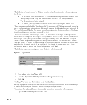
...before configuring the device: • The IP address to be assigned to the VLAN 1 interface through which the device is to be managed (by default, every port is left blank. The following login screen is displayed when the device is off). Login Screen 1 Enter admin in Managed Mode). ...• The IP subnet mask for the network • The default gateway (next hop router) IP address for configuring the default route. The switch supports the following browsers: Microsoft IE V6.x and higher, and Mozilla. To change User name and ...
...before configuring the device: • The IP address to be assigned to the VLAN 1 interface through which the device is to be managed (by default, every port is left blank. The following login screen is displayed when the device is off). Login Screen 1 Enter admin in Managed Mode). ...• The IP subnet mask for the network • The default gateway (next hop router) IP address for configuring the default route. The switch supports the following browsers: Microsoft IE V6.x and higher, and Mozilla. To change User name and ...
User's Guide
Page 35
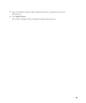
The switch is configured with the updated configuration parameters. 35 2 Enter the IP address, Subnet Mask and Default Gateway as supplied by the System Administrator. 3 Click Apply Changes.
The switch is configured with the updated configuration parameters. 35 2 Enter the IP address, Subnet Mask and Default Gateway as supplied by the System Administrator. 3 Click Apply Changes.
User's Guide
Page 40
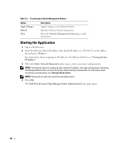
... page or table information. NOTE: Passwords are both case-sensitive and alphanumeric. 4 Click OK. The Dell PowerConnect OpenManage Switch Administrator home page opens. 40 PowerConnect Switch Management Buttons Button Apply Changes Refresh Print Description Applies changes to the Ethernet Switch, see "Managed ... user name and password. Starting the Application 1 Open a Web browser. 2 Enter the Ethernet Switch IP address (the default IP address is configured with a default IP address, user login and password. NOTE: The Ethernet switch is : 192.168.2.1) in the address bar and press...
... page or table information. NOTE: Passwords are both case-sensitive and alphanumeric. 4 Click OK. The Dell PowerConnect OpenManage Switch Administrator home page opens. 40 PowerConnect Switch Management Buttons Button Apply Changes Refresh Print Description Applies changes to the Ethernet Switch, see "Managed ... user name and password. Starting the Application 1 Open a Web browser. 2 Enter the Ethernet Switch IP address (the default IP address is configured with a default IP address, user login and password. NOTE: The Ethernet switch is : 192.168.2.1) in the address bar and press...
User's Guide
Page 44
.... Secure Mode (2748 only) - When checked, enables the secure mode. The IP Address, Subnet Mask and Default Gateway are defined, and the switch is configured according to the new IP and Default Gateway addresses received from the DHCP server to assign a dynamic IP Address, Subnet Mask Address, and... serial number, assigned by the manufacturer. The switch status parameters are then set the static IP Address, Subnet Mask and the device's static Default Gateway Address. Specifies the amount of time since the last switch reset. As soon as Apply Changes is currently running. To open the page...
.... Secure Mode (2748 only) - When checked, enables the secure mode. The IP Address, Subnet Mask and Default Gateway are defined, and the switch is configured according to the new IP and Default Gateway addresses received from the DHCP server to assign a dynamic IP Address, Subnet Mask Address, and... serial number, assigned by the manufacturer. The switch status parameters are then set the static IP Address, Subnet Mask and the device's static Default Gateway Address. Specifies the amount of time since the last switch reset. As soon as Apply Changes is currently running. To open the page...

User's Guide
Page 45
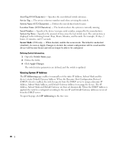
... to the device. Specifies the static IP Address currently assigned to acquire the network configuration dynamically. Default Gateway - Activates the IP Address, Subnet Mask Address, and Default Gateway Address, received from the DHCP server. Specifies the subnet mask of the static IP Address,... parameters are not configured to the device. IP Addressing DHCP - IP Address - Specifies the Subnet Mask received from the DHCP server. DHCP Default Gateway - Updating Static IP Address 1 Open the IP Addressing page. 2 Verify that the DHCP field is Disable. Apply DHCP Address -...
... to the device. Specifies the static IP Address currently assigned to acquire the network configuration dynamically. Default Gateway - Activates the IP Address, Subnet Mask Address, and Default Gateway Address, received from the DHCP server. Specifies the subnet mask of the static IP Address,... parameters are not configured to the device. IP Addressing DHCP - IP Address - Specifies the Subnet Mask received from the DHCP server. DHCP Default Gateway - Updating Static IP Address 1 Open the IP Addressing page. 2 Verify that the DHCP field is Disable. Apply DHCP Address -...
User's Guide
Page 46
...Browser address line. NOTE: The new dynamic DHCP IP Address, DHCP Subnet Mask, and DHCP Default Gateway Address received from the DHCP server to assign a new dynamic IP Address, Subnet Mask, and Default Gateway Address to Enable. 3 Click Apply Changes. Record the updated dynamic fields. 4 Check... Apply DHCP Address. The switch is clicked on. A reset-to the device. NOTE: The displayed values are not configured to -Default recovers the device default configuration. 5 Click Apply Changes. The new dynamic DHCP Address is configured in the switch. 6 Enter the new DHCP Address in ...
...Browser address line. NOTE: The new dynamic DHCP IP Address, DHCP Subnet Mask, and DHCP Default Gateway Address received from the DHCP server to assign a new dynamic IP Address, Subnet Mask, and Default Gateway Address to Enable. 3 Click Apply Changes. Record the updated dynamic fields. 4 Check... Apply DHCP Address. The switch is clicked on. A reset-to the device. NOTE: The displayed values are not configured to -Default recovers the device default configuration. 5 Click Apply Changes. The new dynamic DHCP Address is configured in the switch. 6 Enter the new DHCP Address in ...

User's Guide
Page 52
... is applied. All ports must have a PVID defined; The switch VLAN Port Settings parameter(s) change(s) is only used as a port default VLAN ID (PVID). PVID (1-4095) - Tagged and untagged packets are accepted by the interface. Enables or disables incoming filtering by the interface. Updating... port. VLAN 1 cannot be used as the discard VLAN, thus the packets classified to this VLAN are 1-4094. VLAN 4095 is defined as the default VLAN. if no other PVID value is added to untagged packets. Frame Type - The possible values are accepted by the LAG. When a port is...
... is applied. All ports must have a PVID defined; The switch VLAN Port Settings parameter(s) change(s) is only used as a port default VLAN ID (PVID). PVID (1-4095) - Tagged and untagged packets are accepted by the interface. Enables or disables incoming filtering by the interface. Updating... port. VLAN 1 cannot be used as the discard VLAN, thus the packets classified to this VLAN are 1-4094. VLAN 4095 is defined as the default VLAN. if no other PVID value is added to untagged packets. Frame Type - The possible values are accepted by the LAG. When a port is...


