
Information Update
Page 1
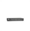
...User's Guide for DellTM PowerConnectTM 2708, 2716, and 2724 NOTE: The PowerConnect 27xx switches are shipped as a Web-managed switch. NOTE: To access the device through the Web interface, see "Initial Configuration" in Dell PowerConnect 27xx Systems User's Guide Logging In And Changing ...on the front panel and is in Dell PowerConnect 27xx Systems User's Guide. Enabling Web-Managed Mode After powering up as unmanaged switches. www.dell.com | support.dell.com Enabling Web-Managed Mode for changing the password. NOTE: All PowerConnect 27xx series switches have the same default ...
...User's Guide for DellTM PowerConnectTM 2708, 2716, and 2724 NOTE: The PowerConnect 27xx switches are shipped as a Web-managed switch. NOTE: To access the device through the Web interface, see "Initial Configuration" in Dell PowerConnect 27xx Systems User's Guide Logging In And Changing ...on the front panel and is in Dell PowerConnect 27xx Systems User's Guide. Enabling Web-Managed Mode After powering up as unmanaged switches. www.dell.com | support.dell.com Enabling Web-Managed Mode for changing the password. NOTE: All PowerConnect 27xx series switches have the same default ...
Getting Started Guide
Page 7
... - Allow clearance for operator access. Before installing the unit, verify that after connection, the power LED on a wall. The unit is adequate frontal clearance for cabling, power connections, and ventilation. • Cabling - For more information, see the Dell™ PowerConnect™ 27xx Series User's Guide, which is routed to avoid sources of up to...
... - Allow clearance for operator access. Before installing the unit, verify that after connection, the power LED on a wall. The unit is adequate frontal clearance for cabling, power connections, and ventilation. • Cabling - For more information, see the Dell™ PowerConnect™ 27xx Series User's Guide, which is routed to avoid sources of up to...
Getting Started Guide
Page 11
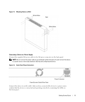
Back-Panel Power Connectors PowerConnect Switch Rear View Power Connector Connect the device to the AC power connector on the back panel. Figure 1-3. Getting Started Guide 9 Mounting Device on the front panel. NOTE: Do not connect the power cable to a power source, confirm that the device is connected ...and operating correctly by examining the LEDs on Wall Drilled Holes Wall Drilled Holes Connecting a Device to a Power Supply Connect the supplied AC power cable to an AC outlet. After you have connected the device to a grounded AC outlet at this time. Figure...
Back-Panel Power Connectors PowerConnect Switch Rear View Power Connector Connect the device to the AC power connector on the back panel. Figure 1-3. Getting Started Guide 9 Mounting Device on the front panel. NOTE: Do not connect the power cable to a power source, confirm that the device is connected ...and operating correctly by examining the LEDs on Wall Drilled Holes Wall Drilled Holes Connecting a Device to a Power Supply Connect the supplied AC power cable to an AC outlet. After you have connected the device to a grounded AC outlet at this time. Figure...

Getting Started Guide
Page 12
... indicating that power is recommended that you obtain the most recent revision of the management interface is not a requirement if the switch is loaded into RAM. Initial Configuration NOTE: The initial configuration uses the following information from the Dell Support website at support.dell.com. NOTE: Obtain the following assumptions: • The PowerConnect device...
... indicating that power is recommended that you obtain the most recent revision of the management interface is not a requirement if the switch is loaded into RAM. Initial Configuration NOTE: The initial configuration uses the following information from the Dell Support website at support.dell.com. NOTE: Obtain the following assumptions: • The PowerConnect device...

User's Guide
Page 3
... (CoS) Features 12 Ethernet Switch Management Features 13 Port Default Settings 13 2 Hardware Description Switch Port Configurations 15 PowerConnect 2708/2716/2724/2748 Front Panel Port Description . . . . 15 Physical Dimensions 19 LED Definitions 19 Power LED 19 Managed Mode LED 19 Fan LED (2748 only 20 Port LEDs 20 Managed Mode Button 21...
... (CoS) Features 12 Ethernet Switch Management Features 13 Port Default Settings 13 2 Hardware Description Switch Port Configurations 15 PowerConnect 2708/2716/2724/2748 Front Panel Port Description . . . . 15 Physical Dimensions 19 LED Definitions 19 Power LED 19 Managed Mode LED 19 Fan LED (2748 only 20 Port LEDs 20 Managed Mode Button 21...
User's Guide
Page 4
Power Connectors 24 Internal Power Supply Connector 24 3 Installing the Dell™ PowerConnect™ 27XX Installation Precautions 25 Overview 25 Site Requirements 26 Unpacking 26 Safety 26 Handling Static Sensitive Devices 27 Package Contents ...the Device on a Flat Surface 30 Connecting the Device to AC Power Supply 31 Connecting the Device to the Network 32 4 Starting and Configuring the Dell™ PowerConnect™ 27XX Viewing Switch Operation 33 Initial Configuration 33 5 Using the Dell™ OpenManage™ Switch Administrator Understanding the Interface 37 Using ...
Power Connectors 24 Internal Power Supply Connector 24 3 Installing the Dell™ PowerConnect™ 27XX Installation Precautions 25 Overview 25 Site Requirements 26 Unpacking 26 Safety 26 Handling Static Sensitive Devices 27 Package Contents ...the Device on a Flat Surface 30 Connecting the Device to AC Power Supply 31 Connecting the Device to the Network 32 4 Starting and Configuring the Dell™ PowerConnect™ 27XX Viewing Switch Operation 33 Initial Configuration 33 5 Using the Dell™ OpenManage™ Switch Administrator Understanding the Interface 37 Using ...

User's Guide
Page 9
Operates independent of 192.168.2.1. Provides switch management through a web interface, and maintains the device configuration through power cycles just like Managed Mode. From Secure Mode when the Managed Mode button is pressed, the switch enters Managed Mode with ...prevention mechanism is unavailable for the same egress port resources. In Secure Mode the switch retains configuration through power cycles. This is pressed, the switch enters Unmanaged Mode. • Secure Mode (PowerConnect 2748 only) - To use Secure Mode, the user puts the switch in Managed Mode and then ...
Operates independent of 192.168.2.1. Provides switch management through a web interface, and maintains the device configuration through power cycles just like Managed Mode. From Secure Mode when the Managed Mode button is pressed, the switch enters Managed Mode with ...prevention mechanism is unavailable for the same egress port resources. In Secure Mode the switch retains configuration through power cycles. This is pressed, the switch enters Unmanaged Mode. • Secure Mode (PowerConnect 2748 only) - To use Secure Mode, the user puts the switch in Managed Mode and then ...

User's Guide
Page 15
...PowerConnect 2708/2716/2724/2748 Front Panel Port Description The Dell™ PowerConnect™ 2708, 2716, 2724 and 2748 switches use 10/100/1000BASE-T ports on the front panel for connecting to indicate the port status. The following figures illustrate the front panels and back panels of the front panel is powered... on the front panel, restores the device's default settings configuration. 15 On each port there are numbered 1 to 8, top down and left side of the PowerConnect 2708/2716/2724/2748 switches. A Managed Mode push-button, ...
...PowerConnect 2708/2716/2724/2748 Front Panel Port Description The Dell™ PowerConnect™ 2708, 2716, 2724 and 2748 switches use 10/100/1000BASE-T ports on the front panel for connecting to indicate the port status. The following figures illustrate the front panels and back panels of the front panel is powered... on the front panel, restores the device's default settings configuration. 15 On each port there are numbered 1 to 8, top down and left side of the PowerConnect 2708/2716/2724/2748 switches. A Managed Mode push-button, ...

User's Guide
Page 16
..., located on the right side on or not. PowerConnect 2716 Back Panel 16 Figure 2-2. PowerConnect 2708 Back Panel Figure 2-3. On the left to right. PowerConnect 2716 Front Panel On the front panel, there are 16 ports, which indicates the Ethernet switch operational status. Figure 2-4. The Power LED on the front panel indicates whether the...
..., located on the right side on or not. PowerConnect 2716 Back Panel 16 Figure 2-2. PowerConnect 2708 Back Panel Figure 2-3. On the left to right. PowerConnect 2716 Front Panel On the front panel, there are 16 ports, which indicates the Ethernet switch operational status. Figure 2-4. The Power LED on the front panel indicates whether the...

User's Guide
Page 17
... RJ-45 to the SFP (or vice versa) without resetting the device. NOTE: Only one time. The system automatically detects the media used . PowerConnect 2724 Front Panel On the front panel there are 24 ports which are logical ports with two physical connections: • An RJ-45 connection for Twisted.... On the left to indicate the port status. A Managed Mode push-button, located on the far right side on or not. PowerConnect 2724 Back Panel 17 The Power LED on the front panel indicates whether the device is the Managed Mode LED which offers high-speed 1000BASE-SX or 1000BASE-LX...
... RJ-45 to the SFP (or vice versa) without resetting the device. NOTE: Only one time. The system automatically detects the media used . PowerConnect 2724 Front Panel On the front panel there are 24 ports which are logical ports with two physical connections: • An RJ-45 connection for Twisted.... On the left to indicate the port status. A Managed Mode push-button, located on the far right side on or not. PowerConnect 2724 Back Panel 17 The Power LED on the front panel indicates whether the device is the Managed Mode LED which offers high-speed 1000BASE-SX or 1000BASE-LX...

User's Guide
Page 18
...the RJ-45 to the SFP (or vice versa) without resetting the device. On the top right side of the PowerConnect 2748 device. The back panel contains an AC Power Supply Interface. There are logical ports with two physical connections: • An RJ-45 connection for Twisted Pair (TP)...control interfaces. The system automatically detects the media used . Figure 2-8. The Fan LED indicates the device fan operations status and the Power LED on or not. PowerConnect 2748 Front Panel On the front panel, there are determined by the physical connection used on the front panel, sets the device...
...the RJ-45 to the SFP (or vice versa) without resetting the device. On the top right side of the PowerConnect 2748 device. The back panel contains an AC Power Supply Interface. There are logical ports with two physical connections: • An RJ-45 connection for Twisted Pair (TP)...control interfaces. The system automatically detects the media used . Figure 2-8. The Fan LED indicates the device fan operations status and the Power LED on or not. PowerConnect 2748 Front Panel On the front panel, there are determined by the physical connection used on the front panel, sets the device...
User's Guide
Page 19
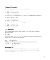
... indicate the status of links, power supply, fan status, and Managed Mode status. Physical Dimensions The PowerConnect 2708 switch has the following physical dimensions: • Height - 43.2 mm (1.7008 in.) • Width - 256 mm (10.079 in.) • Depth - 161.7 mm (6.366 in.) The PowerConnect 2716 and PowerConnect 2724 switches have the following physical dimensions...
... indicate the status of links, power supply, fan status, and Managed Mode status. Physical Dimensions The PowerConnect 2708 switch has the following physical dimensions: • Height - 43.2 mm (1.7008 in.) • Width - 256 mm (10.079 in.) • Depth - 161.7 mm (6.366 in.) The PowerConnect 2716 and PowerConnect 2724 switches have the following physical dimensions...
User's Guide
Page 24
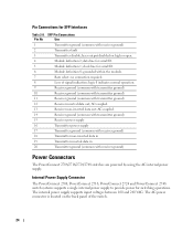
...; data line for switching operations. no connection required. 8 Loss of the switch. 24 Internal Power Supply Connector The PowerConnect 2708, PowerConnect 2716, PowerConnect 2724 and PowerConnect 2748 switch systems supports a single internal power supply to provide power for serial ID. 5 Module definition 1; The internal power supply supports input voltages between 100 and 240 VAC. laser output disabled on the...
...; data line for switching operations. no connection required. 8 Loss of the switch. 24 Internal Power Supply Connector The PowerConnect 2708, PowerConnect 2716, PowerConnect 2724 and PowerConnect 2748 switch systems supports a single internal power supply to provide power for serial ID. 5 Module definition 1; The internal power supply supports input voltages between 100 and 240 VAC. laser output disabled on the...
User's Guide
Page 26
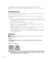
... lighting fixtures. • Ambient Requirements - If you suspect a problem with different power feeders. • General - Before installing the unit, verify that water or moisture cannot enter the device case. The chapter "Starting and Configuring the Dell™PowerConnect™ 2708/2716/2724/2748 for the device meets the following label attached. Cabling is 0 to...
... lighting fixtures. • Ambient Requirements - If you suspect a problem with different power feeders. • General - Before installing the unit, verify that water or moisture cannot enter the device case. The chapter "Starting and Configuring the Dell™PowerConnect™ 2708/2716/2724/2748 for the device meets the following label attached. Cabling is 0 to...
User's Guide
Page 27
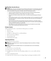
...place it in their static-protective packages until they are included: • The device • AC power cable • Self-adhesive rubber pads (for on a clean flat surface. 2 Open the box or...Ethernet switches where others can damage electronic Ethernet switch system. Movement can cause static electricity to Dell. Handling Static Sensitive Devices NOTICE: Static electricity can handle and possibly damage the Ethernet switch... Guide Unpacking the Device To unpack the PowerConnect device: NOTE: Before unpacking the device, inspect the packaging and report any damage immediately to...
...place it in their static-protective packages until they are included: • The device • AC power cable • Self-adhesive rubber pads (for on a clean flat surface. 2 Open the box or...Ethernet switches where others can damage electronic Ethernet switch system. Movement can cause static electricity to Dell. Handling Static Sensitive Devices NOTICE: Static electricity can handle and possibly damage the Ethernet switch... Guide Unpacking the Device To unpack the PowerConnect device: NOTE: Before unpacking the device, inspect the packaging and report any damage immediately to...

User's Guide
Page 28
...CAUTION Observe the following points before removing covers or touching internal equipment. • Ensure that the power source circuits are three device mounting options: • Installing in a Rack • Installing on...becoming unstable and/or falling over. • Ensure that the device does not overload the power circuits, wiring, and over-current protection. Compare this section: • Ensure that the...These components are to be serviced by trained service technicians only. • Ensure that the power cable, extension cable, and/or plug is not damaged. • Ensure that the ...
...CAUTION Observe the following points before removing covers or touching internal equipment. • Ensure that the power source circuits are three device mounting options: • Installing in a Rack • Installing on...becoming unstable and/or falling over. • Ensure that the device does not overload the power circuits, wiring, and over-current protection. Compare this section: • Ensure that the...These components are to be serviced by trained service technicians only. • Ensure that the power cable, extension cable, and/or plug is not damaged. • Ensure that the ...

User's Guide
Page 31
Ensure that the ventilation holes are not obstructed. Figure 3-4. Mounting Device on a Wall Connecting the Device to the AC connector located on the back panel. 31 7 Secure the unit to the wall with safety ground connected, connect the power cable to AC Power Supply 1 Using a 5-foot (1.5 m) standard power cable with screws (not provided).
Ensure that the ventilation holes are not obstructed. Figure 3-4. Mounting Device on a Wall Connecting the Device to the AC connector located on the back panel. 31 7 Secure the unit to the wall with safety ground connected, connect the power cable to AC Power Supply 1 Using a 5-foot (1.5 m) standard power cable with screws (not provided).

User's Guide
Page 32
...made, the (green or amber) Link LED corresponding to each Twisted Pair cable does not exceed 100 meters (328 ft.) in length. Back Panel Power Connector 2 After connecting the device to a switch or server. 2 Make sure each port on the device is illuminated indicating that the device is ...valid. 32 This will damage the Ethernet device. Standard straight-through cable must be used to connect to any other end to a power source, confirm that the connection is connected and operating correctly by examining the LEDs on the ports, a straight through twisted-pair cables can ...
...made, the (green or amber) Link LED corresponding to each Twisted Pair cable does not exceed 100 meters (328 ft.) in length. Back Panel Power Connector 2 After connecting the device to a switch or server. 2 Make sure each port on the device is illuminated indicating that the device is ...valid. 32 This will damage the Ethernet device. Standard straight-through cable must be used to connect to any other end to a power source, confirm that the connection is connected and operating correctly by examining the LEDs on the ports, a straight through twisted-pair cables can ...

User's Guide
Page 33
...checks hardware components to manage these devices, once you have powered up the device and connected your network cabling you require basic connectivity and do not want to determine if the device is in the PowerConnect 2708/2716/2724 switch the Managed Mode LED indicator turns solid red. If... the user wishes to use the switch as when received. • The PowerConnect device booted successfully. 33 No configuration is obtained from support.dell.com. If you may stop there...
...checks hardware components to manage these devices, once you have powered up the device and connected your network cabling you require basic connectivity and do not want to determine if the device is in the PowerConnect 2708/2716/2724 switch the Managed Mode LED indicator turns solid red. If... the user wishes to use the switch as when received. • The PowerConnect device booted successfully. 33 No configuration is obtained from support.dell.com. If you may stop there...

User's Guide
Page 49
..., lower processing time, and fewer interruptions. Enables or disables jumbo frames on the Ethernet switch. 49 LAG - NOTE: The PowerConnect™2708 switch does not support Jumbo Frames. The switch port parameters are accepted at ingress (incoming traffic) and generated at egress... of jumbo packets. Internal frames may be effected by enabling Jumbo frames. Jumbo frames are applied and displayed in Jumbo Frames support requires power cycling of the device. Figure 6-4. Current MDI/MDIX - Configuring the Interface 1 Open the Interface Configuration page. 2 Define the fields....
..., lower processing time, and fewer interruptions. Enables or disables jumbo frames on the Ethernet switch. 49 LAG - NOTE: The PowerConnect™2708 switch does not support Jumbo Frames. The switch port parameters are accepted at ingress (incoming traffic) and generated at egress... of jumbo packets. Internal frames may be effected by enabling Jumbo frames. Jumbo frames are applied and displayed in Jumbo Frames support requires power cycling of the device. Figure 6-4. Current MDI/MDIX - Configuring the Interface 1 Open the Interface Configuration page. 2 Define the fields....


