
Information Update
Page 1
...IP Address" in the User's Guide for DellTM PowerConnectTM 2708, 2716, and 2724 NOTE: The PowerConnect 27xx switches are shipped as a Web-managed switch. In this switch, follow the steps in Dell PowerConnect 27xx Systems User's Guide. www.dell.com | support.dell.com Enabling Web-Managed Mode for changing the password.... prevent accidental mode changes. March 2005 NOTE: When changing between the unmanaged and Web-managed modes, the switch is reset to Web-managed mode and the Managed Mode LED will be illuminated green. Enabling Web-Managed Mode After powering up as unmanaged ...
...IP Address" in the User's Guide for DellTM PowerConnectTM 2708, 2716, and 2724 NOTE: The PowerConnect 27xx switches are shipped as a Web-managed switch. In this switch, follow the steps in Dell PowerConnect 27xx Systems User's Guide. www.dell.com | support.dell.com Enabling Web-Managed Mode for changing the password.... prevent accidental mode changes. March 2005 NOTE: When changing between the unmanaged and Web-managed modes, the switch is reset to Web-managed mode and the Managed Mode LED will be illuminated green. Enabling Web-Managed Mode After powering up as unmanaged ...
Information Update
Page 2
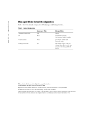
.... Other trademarks and trade names may be used in this document is strictly forbidden. Resets each time you change without the written permission of Dell Inc. Dell Inc. Trademarks used in this text: Dell and the DELL logo are trademarks of Unmanaged and Managed modes. Table 1. Default Configuration Managed Mode LED IP Unmanaged Mode Off...
.... Other trademarks and trade names may be used in this document is strictly forbidden. Resets each time you change without the written permission of Dell Inc. Dell Inc. Trademarks used in this text: Dell and the DELL logo are trademarks of Unmanaged and Managed modes. Table 1. Default Configuration Managed Mode LED IP Unmanaged Mode Off...

User's Guide
Page 5
Resetting the Device 41 Displaying Configuration on Demand 42 6 Configuring System Information Defining Switch Information 43 Viewing the Switch Status 43 Viewing System IP Address 44 ...
Resetting the Device 41 Displaying Configuration on Demand 42 6 Configuring System Information Defining Switch Information 43 Viewing the Switch Status 43 Viewing System IP Address 44 ...

User's Guide
Page 17
...An SFP port for fiber connection. NOTE: The system can be disabled. On the left to the SFP (or vice versa) without resetting the device. The Power LED on the front panel indicates whether the device is the Managed Mode LED which offers high-speed 1000BASE-SX ...designated as ports 23 and 24, for swappable optical transceiver, which indicates the Ethernet switch operational status. PowerConnect 2724 Back Panel 17 Figure 2-6. The system automatically detects the media used . PowerConnect 2724 Front Panel On the front panel there are 24 ports which are LEDs to 24, top ...
...An SFP port for fiber connection. NOTE: The system can be disabled. On the left to the SFP (or vice versa) without resetting the device. The Power LED on the front panel indicates whether the device is the Managed Mode LED which offers high-speed 1000BASE-SX ...designated as ports 23 and 24, for swappable optical transceiver, which indicates the Ethernet switch operational status. PowerConnect 2724 Back Panel 17 Figure 2-6. The system automatically detects the media used . PowerConnect 2724 Front Panel On the front panel there are 24 ports which are LEDs to 24, top ...

User's Guide
Page 18
... SFP port will be the active port, whereas the RJ-45 port will be used at any one of the two physical connections of the PowerConnect 2748 device. NOTE: Only one time. Figure 2-7. On each port, there are determined by the physical connection used on the front panel, sets the device... media used . The following figure illustrates the back panel of a combo port can switch from the RJ-45 to the SFP (or vice versa) without resetting the device. A Managed Mode push-button, located on the far right side on a combo port, and utilizes the information in all the control interfaces. There...
... SFP port will be the active port, whereas the RJ-45 port will be used at any one of the two physical connections of the PowerConnect 2748 device. NOTE: Only one time. Figure 2-7. On each port, there are determined by the physical connection used on the front panel, sets the device... media used . The following figure illustrates the back panel of a combo port can switch from the RJ-45 to the SFP (or vice versa) without resetting the device. A Managed Mode push-button, located on the far right side on a combo port, and utilizes the information in all the control interfaces. There...
User's Guide
Page 23
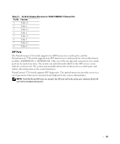
The system automatically detects the media used at any time. PowerConnect 2724 switch supports SFP diagnostics. The optical transceiver provides access to a set of a combo port can... can be used on a combo port, and utilizes this information in the control interfaces. SFP Ports The PowerConnect 2724 switch supports two SFP transceivers combo ports, and the PowerConnect 2748 switch supports four SFP transceivers combo ports for 10/100/ 1000BASE-T Ethernet Port Pin No Function 1 ...-LX). The system can be monitored and displayed to the SFP (or vice versa) without a system reset.
The system automatically detects the media used at any time. PowerConnect 2724 switch supports SFP diagnostics. The optical transceiver provides access to a set of a combo port can... can be used on a combo port, and utilizes this information in the control interfaces. SFP Ports The PowerConnect 2724 switch supports two SFP transceivers combo ports, and the PowerConnect 2748 switch supports four SFP transceivers combo ports for 10/100/ 1000BASE-T Ethernet Port Pin No Function 1 ...-LX). The system can be monitored and displayed to the SFP (or vice versa) without a system reset.
User's Guide
Page 41
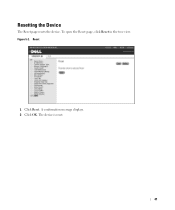
A confirmation message displays. 2 Click OK. Resetting the Device The Reset page resets the device. The device is reset. 41 Figure 5-2. Reset 1 Click Reset. To open the Reset page, click Reset in the tree view.
A confirmation message displays. 2 Click OK. Resetting the Device The Reset page resets the device. The device is reset. 41 Figure 5-2. Reset 1 Click Reset. To open the Reset page, click Reset in the tree view.
User's Guide
Page 44
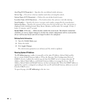
... the manufacturer. When the DHCP Address is applied, the switch is updated. Location Name (0-32 Characters) - Specifies the amount of time since the last switch reset. Serial Number - The service reference number used when servicing the switch. When checked, enables the secure mode. The switch status parameters are then set the...
... the manufacturer. When the DHCP Address is applied, the switch is updated. Location Name (0-32 Characters) - Specifies the amount of time since the last switch reset. Serial Number - The service reference number used when servicing the switch. When checked, enables the secure mode. The switch status parameters are then set the...
User's Guide
Page 46
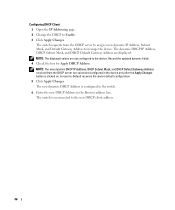
... Address, Subnet Mask, and Default Gateway Address to manage the device. The switch is reconnected to -Default recovers the device default configuration. 5 Click Apply Changes. A reset-to the new DHCP client address. 46 NOTE: The displayed values are not configured to Enable. 3 Click Apply Changes. The new dynamic DHCP Address is...
... Address, Subnet Mask, and Default Gateway Address to manage the device. The switch is reconnected to -Default recovers the device default configuration. 5 Click Apply Changes. A reset-to the new DHCP client address. 46 NOTE: The displayed values are not configured to Enable. 3 Click Apply Changes. The new dynamic DHCP Address is...

User's Guide
Page 50
All packets forwarded by toggling through the Port Control settings. The interface is for Jumbo Frames support. After Reset - The Jumbo Frames are tagged. Ports are untagged. 50 Figure 6-5. Current - Enabling Jumbo Frames 1 Open the Jumbo Frames page. 2 Select Enabled in the tree view. ...
All packets forwarded by toggling through the Port Control settings. The interface is for Jumbo Frames support. After Reset - The Jumbo Frames are tagged. Ports are untagged. 50 Figure 6-5. Current - Enabling Jumbo Frames 1 Open the Jumbo Frames page. 2 Select Enabled in the tree view. ...
User's Guide
Page 56
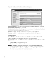
... be downloaded. Boot Code - Enables initiating an image download via HTTP - Indicates the file to which displays the download progress. It is downloaded. File Download (PowerConnect 2748 Switch Configuration) Firmware Download - Source File Name (1-159 Characters)- The Firmware file is recommended to designate that the nonactive image will become the active...
... be downloaded. Boot Code - Enables initiating an image download via HTTP - Indicates the file to which displays the download progress. It is downloaded. File Download (PowerConnect 2748 Switch Configuration) Firmware Download - Source File Name (1-159 Characters)- The Firmware file is recommended to designate that the nonactive image will become the active...
User's Guide
Page 59
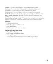
...the default user for device configuration, when selected. Save User/Password - When selected, specifies that the factory configuration default files should be reset. Default User - Copying Files 1 Open the Copy Files page. 2 Define the Source and Destination fields. 3 Click Apply Changes. 4 ...Default Settings 1 Open the Copy Files page. 2 Click Restore Company Factory Defaults 3 Click Apply Changes. Reset to the default user and password, when selected. Resets the device to Default User/Password - Uses the default password for device configuration, when selected. Uses ...
...the default user for device configuration, when selected. Save User/Password - When selected, specifies that the factory configuration default files should be reset. Default User - Copying Files 1 Open the Copy Files page. 2 Define the Source and Destination fields. 3 Click Apply Changes. 4 ...Default Settings 1 Open the Copy Files page. 2 Click Restore Company Factory Defaults 3 Click Apply Changes. Reset to the default user and password, when selected. Resets the device to Default User/Password - Uses the default password for device configuration, when selected. Uses ...

User's Guide
Page 75
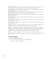
... occurred on the interface since the system was last reset. 75 Figure 8-1. Specifies the port or LAG for viewing network information from a remote location. The RMON Statistics page contains links for which provides network traffic statistics. RMON Statistics Interface - NOTE: The PowerConnect™ 2708/2716/2724/2748 devices support one RMON group for...
... occurred on the interface since the system was last reset. 75 Figure 8-1. Specifies the port or LAG for viewing network information from a remote location. The RMON Statistics page contains links for which provides network traffic statistics. RMON Statistics Interface - NOTE: The PowerConnect™ 2708/2716/2724/2748 devices support one RMON group for...
User's Guide
Page 76
... field. This number includes bad packets and FCS octets, but including FCS octets) received on the interface since the system was last reset. This number does not include Multicast packets. Oversize Packets - Jabbers - Number of octets received on the interface since the system was last... Packets Received - CRC & Align Errors - Undersize Packets - Number of good Broadcast packets received on the interface since the system was last reset. The total number of xx Bytes - The allowed range to detect jabber is between 20 ms and 150 ms. Collisions - Frames of ...
... field. This number includes bad packets and FCS octets, but including FCS octets) received on the interface since the system was last reset. This number does not include Multicast packets. Oversize Packets - Jabbers - Number of octets received on the interface since the system was last... Packets Received - CRC & Align Errors - Undersize Packets - Number of good Broadcast packets received on the interface since the system was last reset. The total number of xx Bytes - The allowed range to detect jabber is between 20 ms and 150 ms. Collisions - Frames of ...


