
Owner's Manual - Mini Tower
Page 4
......27 Installing the System Board...28 System Board Components...29 3 System Setup...31 Boot Sequence...31 Navigation Keys...31 System Setup Options...32 Updating the BIOS ...40 Jumper Settings...41 System and Setup Password...41 Assigning a System Password and Setup Password 41 Deleting or Changing an Existing System and/or Setup... Enhanced Pre-Boot System Assessment (ePSA) Diagnostics 45 5 Troubleshooting Your Computer 47 Power LED Diagnostics...47 Beep Code...48 Error Messages...48 6 Specifications...53 7 Contacting Dell ...59
......27 Installing the System Board...28 System Board Components...29 3 System Setup...31 Boot Sequence...31 Navigation Keys...31 System Setup Options...32 Updating the BIOS ...40 Jumper Settings...41 System and Setup Password...41 Assigning a System Password and Setup Password 41 Deleting or Changing an Existing System and/or Setup... Enhanced Pre-Boot System Assessment (ePSA) Diagnostics 45 5 Troubleshooting Your Computer 47 Power LED Diagnostics...47 Beep Code...48 Error Messages...48 6 Specifications...53 7 Contacting Dell ...59

Owner's Manual - Mini Tower
Page 31
...; Enable or disable integrated devices • Set performance and power management thresholds • Manage your computer hardware and specify BIOS‐level options. During the Power-on Self Test (POST), when the Dell logo appears, you can: • Access System Setup by pressing key • Bring up the one-time boot menu...
...; Enable or disable integrated devices • Set performance and power management thresholds • Manage your computer hardware and specify BIOS‐level options. During the Power-on Self Test (POST), when the Dell logo appears, you can: • Access System Setup by pressing key • Bring up the one-time boot menu...

Owner's Manual - Mini Tower
Page 32
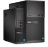
... Allows you to select a value in the selected field (if applicable) or follow the link in this section may or may not appear Table 2. Displays BIOS Version, Service Tag, Asset Tag, Ownership Tag, Ownership Date, Manufacture Date, and the Express Service Code. • Memory Information - The changes to the next focus...
... Allows you to select a value in the selected field (if applicable) or follow the link in this section may or may not appear Table 2. Displays BIOS Version, Service Tag, Asset Tag, Ownership Tag, Ownership Date, Manufacture Date, and the Express Service Code. • Memory Information - The changes to the next focus...

Owner's Manual - Mini Tower
Page 34
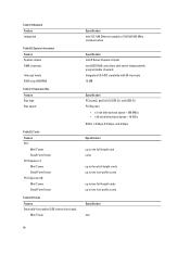
...; Enable Rear Dual USB Ports • Enable Rear Quad USB Ports • Enable Front USB Ports NOTE: USB keyboard and mouse always work in the BIOS setup irrespective of characters allowed for USB configuration differ based on restarts (warm boots). 34 Option Audio Miscellaneous Devices Description If USB port is enabled...
...; Enable Rear Dual USB Ports • Enable Rear Quad USB Ports • Enable Front USB Ports NOTE: USB keyboard and mouse always work in the BIOS setup irrespective of characters allowed for USB configuration differ based on restarts (warm boots). 34 Option Audio Miscellaneous Devices Description If USB port is enabled...
Owner's Manual - Mini Tower
Page 35
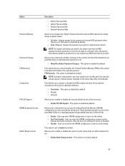
... Setup Lockout Table 5. Also, the system will revert to the system and hard disk passwords are not affected if you activate or disable the BIOS module interface of the processor. • Enable CPU XD Support - Allows you to determine whether changes to disabled. • Disable - TPM...powered on any module bay HDDs that may enter OROM configuration screens via the hotkey. Changes to the Intel RAID (CTRL+I) or Intel Management Engine BIOS Extension (CTRL+P/F12). • Enable - User may be present. This option is not set . • Enable Admin Setup Lockout - ...
... Setup Lockout Table 5. Also, the system will revert to the system and hard disk passwords are not affected if you activate or disable the BIOS module interface of the processor. • Enable CPU XD Support - Allows you to determine whether changes to disabled. • Disable - TPM...powered on any module bay HDDs that may enter OROM configuration screens via the hotkey. Changes to the Intel RAID (CTRL+I) or Intel Management Engine BIOS Extension (CTRL+P/F12). • Enable - User may be present. This option is not set . • Enable Admin Setup Lockout - ...

Owner's Manual - Mini Tower
Page 38
... is enabled by a special LAN signal. If option enables will synchronize emails or social media application that displays the keystroke sequence required to enter the BIOS Boot Option Menu. • Enable F12 Boot Option menu - The options differ based on by special WLAN signals. (For Ultra Small Form Factor only) •...
... is enabled by a special LAN signal. If option enables will synchronize emails or social media application that displays the keystroke sequence required to enter the BIOS Boot Option Menu. • Enable F12 Boot Option menu - The options differ based on by special WLAN signals. (For Ultra Small Form Factor only) •...

Owner's Manual - Mini Tower
Page 40
... in the System Configuration group is set to Enabled with ImageServer and when Client DHCP is set to Enabled with Cloud Desktop. System Logs Option BIOS events Description Displays the system event log and allows you are unable to Static IP. If you to clear the log. • Clear Log ... address of the client. Table 12. NOTE: This field is only relevant when the Integrated NIC control in the System Configuration group is set to dell.com/support. 3. The default setting is 255.255.255.255. The default setting is 255.255.255.255. NOTE: If you have your computer ...
... in the System Configuration group is set to Enabled with ImageServer and when Client DHCP is set to Enabled with Cloud Desktop. System Logs Option BIOS events Description Displays the system event log and allows you are unable to Static IP. If you to clear the log. • Clear Log ... address of the client. Table 12. NOTE: This field is only relevant when the Integrated NIC control in the System Configuration group is set to dell.com/support. 3. The default setting is 255.255.255.255. The default setting is 255.255.255.255. NOTE: If you have your computer ...

Owner's Manual - Mini Tower
Page 41
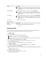
... to save the file on your computer. To enter a system setup, press immediately after a power-on your computer. In the System BIOS or System Setup screen, select System Security and press . 41 Select your preferred download method in the Please select your computer appears. 8.... the existing System Password and Setup Password is Unlocked. Password that you need not provide the system password to install the updated BIOS settings on your system. Jumper Settings Jumper Setting Description PSWD RTCRST Default pin 1 and 2 Password features are enabled Real-time clock...
... to save the file on your computer. To enter a system setup, press immediately after a power-on your computer. In the System BIOS or System Setup screen, select System Security and press . 41 Select your preferred download method in the Please select your computer appears. 8.... the existing System Password and Setup Password is Unlocked. Password that you need not provide the system password to install the updated BIOS settings on your system. Jumper Settings Jumper Setting Description PSWD RTCRST Default pin 1 and 2 Password features are enabled Real-time clock...

Owner's Manual - Mini Tower
Page 42
.../or Setup password, re-enter the new password when promoted. To enter the System Setup, press immediately after a power-on or reboot. 1. In the System BIOS or System Setup screen, select System Security and press . In the System Security screen, verify that the Password Status is Locked. Select System Password, alter...
.../or Setup password, re-enter the new password when promoted. To enter the System Setup, press immediately after a power-on or reboot. 1. In the System BIOS or System Setup screen, select System Security and press . In the System Security screen, verify that the Password Status is Locked. Select System Password, alter...

Owner's Manual - Mini Tower
Page 45
Using this program with the BIOS and is launched by the BIOS internally. The diagnostics starts running diagnostics is embedded with other computers may cause invalid results or error messages. The ePSA is to test only your ... your computer's hardware without requiring additional equipment or risking data loss. Enhanced Pre-Boot System Assessment (ePSA) Diagnostics The ePSA diagnostics (also known as the Dell logo appears. 3. The Enhanced Pre-boot System Assessment window is displayed, listing all the detected devices. 4. As the computer boots, press the key as system...
Using this program with the BIOS and is launched by the BIOS internally. The diagnostics starts running diagnostics is embedded with other computers may cause invalid results or error messages. The ePSA is to test only your ... your computer's hardware without requiring additional equipment or risking data loss. Enhanced Pre-Boot System Assessment (ePSA) Diagnostics The ePSA diagnostics (also known as the Dell logo appears. 3. The Enhanced Pre-boot System Assessment window is displayed, listing all the detected devices. 4. As the computer boots, press the key as system...

Owner's Manual - Mini Tower
Page 47
... Amber LED State 2,1 2,2 2,3 2, 4 2,5 2,6 2,7 3,1 3,2 3,3 3,4 3,5 3,6 Description system board failure system board, PSU or PSU cabling failure system board, memory or CPU failure coin-cell battery failure corrupt BIOS CPU configuration failure or CPU failure memory modules are detected, but a memory failure possible peripheral card or system board failure possible USB failure no longer...
... Amber LED State 2,1 2,2 2,3 2, 4 2,5 2,6 2,7 3,1 3,2 3,3 3,4 3,5 3,6 Description system board failure system board, PSU or PSU cabling failure system board, memory or CPU failure coin-cell battery failure corrupt BIOS CPU configuration failure or CPU failure memory modules are detected, but a memory failure possible peripheral card or system board failure possible USB failure no longer...

Owner's Manual - Mini Tower
Page 48
...you have spelled the command correctly, put spaces in resolving this problem, please note this system have failed at booting this checkpoint and contact Dell Technical Support. Bad error-correction code (ECC) on screen Beep Code The computer can emit a series of beeps during start-up if the... read the data. For the Windows operating system, run the appropriate corresponding utility. 48 The MFG_MODE jumper has been set of beeps, the BIOS should detect if the user presses the power button. Amber LED State 3,7 Description some other operating system, run the chkdsk utility to check ...
...you have spelled the command correctly, put spaces in resolving this problem, please note this system have failed at booting this checkpoint and contact Dell Technical Support. Bad error-correction code (ECC) on screen Beep Code The computer can emit a series of beeps during start-up if the... read the data. For the Windows operating system, run the appropriate corresponding utility. 48 The MFG_MODE jumper has been set of beeps, the BIOS should detect if the user presses the power button. Amber LED State 3,7 Description some other operating system, run the chkdsk utility to check ...
Owner's Manual - Mini Tower
Page 54
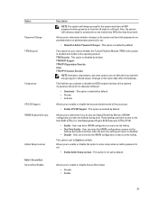
... cards up to two full-height cards up to two low-profile cards Specification two 54 System Information Feature System chipset DMA channels Interrupt levels BIOS chip (NVRAM) Table 21. Cards Feature PCI: Mini Tower Small Form Factor PCI Express x1: Mini Tower Small Form Factor PCI-Express x16: Mini Tower...
... cards up to two full-height cards up to two low-profile cards Specification two 54 System Information Feature System chipset DMA channels Interrupt levels BIOS chip (NVRAM) Table 21. Cards Feature PCI: Mini Tower Small Form Factor PCI Express x1: Mini Tower Small Form Factor PCI-Express x16: Mini Tower...

Owner's Manual - Small Form Factor
Page 4
... Removing the System Board...29 Installing the System Board...30 3 System Setup...31 Boot Sequence...31 Navigation Keys...31 System Setup Options...32 Updating the BIOS ...39 Jumper Settings...40 System and Setup Password...40 Assigning a System Password and Setup Password 40 Deleting or Changing an Existing System and/or Setup... Enhanced Pre-Boot System Assessment (ePSA) Diagnostics 43 5 Troubleshooting Your Computer 45 Power LED Diagnostics...45 Beep Code...46 Error Messages...46 6 Specifications...51 7 Contacting Dell ...57
... Removing the System Board...29 Installing the System Board...30 3 System Setup...31 Boot Sequence...31 Navigation Keys...31 System Setup Options...32 Updating the BIOS ...39 Jumper Settings...40 System and Setup Password...40 Assigning a System Password and Setup Password 40 Deleting or Changing an Existing System and/or Setup... Enhanced Pre-Boot System Assessment (ePSA) Diagnostics 43 5 Troubleshooting Your Computer 45 Power LED Diagnostics...45 Beep Code...46 Error Messages...46 6 Specifications...51 7 Contacting Dell ...57

Owner's Manual - Small Form Factor
Page 31
... Keys Navigation Up arrow Moves to the next field. 31 The boot sequence screen also displays the option to manage your computer hardware and specify BIOS‐level options. During the Power-on Self Test (POST), when the Dell logo appears, you can boot from including the diagnostic option.
... Keys Navigation Up arrow Moves to the next field. 31 The boot sequence screen also displays the option to manage your computer hardware and specify BIOS‐level options. During the Power-on Self Test (POST), when the Dell logo appears, you can boot from including the diagnostic option.

Owner's Manual - Small Form Factor
Page 32
... on the computer and its installed devices, the items listed in which the computer attempts to save any unsaved changes and restarts the system. Displays BIOS Version, Service Tag, Asset Tag, Ownership Tag, Ownership Date, Manufacture Date, and the Express Service Code. • Memory Information - Moves to the previous page till...
... on the computer and its installed devices, the items listed in which the computer attempts to save any unsaved changes and restarts the system. Displays BIOS Version, Service Tag, Asset Tag, Ownership Tag, Ownership Date, Manufacture Date, and the Express Service Code. • Memory Information - Moves to the previous page till...

Owner's Manual - Small Form Factor
Page 34
...; Enable Rear Dual USB 2.0 Ports • Enable Rear Dual USB 3.0 Ports • Enable Front USB Ports NOTE: USB keyboard and mouse always work in the BIOS setup irrespective of characters allowed for the admin and system passwords. 34 This option is enabled by default. • Enter the old password • Enter...
...; Enable Rear Dual USB 2.0 Ports • Enable Rear Dual USB 3.0 Ports • Enable Front USB Ports NOTE: USB keyboard and mouse always work in the BIOS setup irrespective of characters allowed for the admin and system passwords. 34 This option is enabled by default. • Enter the old password • Enter...
Owner's Manual - Small Form Factor
Page 35
... (CTRL+P/F12). • Enable - This option is enabled by default. This field lets you activate or disable the BIOS module interface of the processor. • Enable CPU XD Support - These settings prenvent access to the system and hard disk passwords are permitted when an ...
... (CTRL+P/F12). • Enable - This option is enabled by default. This field lets you activate or disable the BIOS module interface of the processor. • Enable CPU XD Support - These settings prenvent access to the system and hard disk passwords are permitted when an ...

Owner's Manual - Small Form Factor
Page 37
... when the computer is disabled by special WLAN signals. (For Ultra Small Form Factor only) • LAN or WLAN - Allows the system to enter the BIOS Boot Option Menu. • Enable F12 Boot Option menu - Allows the system to be powered on screen displays a message, that displays the keystroke sequence required...
... when the computer is disabled by special WLAN signals. (For Ultra Small Form Factor only) • LAN or WLAN - Allows the system to enter the BIOS Boot Option Menu. • Enable F12 Boot Option menu - Allows the system to be powered on screen displays a message, that displays the keystroke sequence required...
Owner's Manual - Small Form Factor
Page 39
... NIC control in the Please select your BIOS (system setup), on your computer battery is fully charged and connected to locate or find your computer's Service Tag or Express Service Code: NOTE: To locate the Service Tag, click Where is set to dell.com/support. 3. Restart the computer. ...2. NOTE: If you to clear the log. • Clear Log Updating the BIOS It is available. Proceed with ImageServer and when Client DHCP is my Service Tag? Identify...
... NIC control in the Please select your BIOS (system setup), on your computer battery is fully charged and connected to locate or find your computer's Service Tag or Express Service Code: NOTE: To locate the Service Tag, click Where is set to dell.com/support. 3. Restart the computer. ...2. NOTE: If you to clear the log. • Clear Log Updating the BIOS It is available. Proceed with ImageServer and when Client DHCP is my Service Tag? Identify...


