User Guide
Page 50
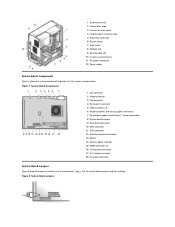
.... Figure 8. System Board Jumpers Table 1 lists the system board jumpers and their settings. System Board Components 1 NIC connector 2 Video connector 3 Fan connector 4 Serial port 2 connector 5 USB connectors (2) 6 Keyboard (lower) and mouse (upper) connectors 7 Parallel port (upper) and serial port 1 (lower) connectors 8 System board jumpers 9 Riser board connector 10 IDE1 connector 11...
.... Figure 8. System Board Jumpers Table 1 lists the system board jumpers and their settings. System Board Components 1 NIC connector 2 Video connector 3 Fan connector 4 Serial port 2 connector 5 USB connectors (2) 6 Keyboard (lower) and mouse (upper) connectors 7 Parallel port (upper) and serial port 1 (lower) connectors 8 System board jumpers 9 Riser board connector 10 IDE1 connector 11...
User Guide
Page 51
... cover as LPT1 Main power input connector 3.3-volt (V) power input connector Riser board connector Serial port connectors Universal Serial Bus (USB) connectors Rotating the Power Supply Away From the System Board (Mini Tower Chassis Only) To access some components on the system... Sockets Connector or Socket AUX_LED B1 DIMM_x DSKT ENET FAN IDEn INTRUSION KYBD MICROPROCESSOR MONITOR MOUSE PANEL PARALLEL POWER_1 POWER_2 RISER SERIALn USB Description Auxiliary power indicator Battery socket Dual in "Removing and Replacing the Computer Cover." Plastic plugs containing a wire fit down ...
... cover as LPT1 Main power input connector 3.3-volt (V) power input connector Riser board connector Serial port connectors Universal Serial Bus (USB) connectors Rotating the Power Supply Away From the System Board (Mini Tower Chassis Only) To access some components on the system... Sockets Connector or Socket AUX_LED B1 DIMM_x DSKT ENET FAN IDEn INTRUSION KYBD MICROPROCESSOR MONITOR MOUSE PANEL PARALLEL POWER_1 POWER_2 RISER SERIALn USB Description Auxiliary power indicator Battery socket Dual in "Removing and Replacing the Computer Cover." Plastic plugs containing a wire fit down ...
User Guide
Page 65
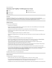
..., file updates, and asset tracking after business hours and on from a server management console. l Universal Serial Bus (USB) capability, which resides in embedded System Setup, the system can simplify connecting peripheral devices such as necessary. Software Features ...Remote Boot. l System memory of up to Contents Page Introduction: Dell™ OptiPlex™ GX100 System User's Guide Overview Hardware Features Software Features Manageability Features ENERGY STAR® Compliance Overview Dell OptiPlex GX100 Managed PC systems are designed around the Intel® Celeron™...
..., file updates, and asset tracking after business hours and on from a server management console. l Universal Serial Bus (USB) capability, which resides in embedded System Setup, the system can simplify connecting peripheral devices such as necessary. Software Features ...Remote Boot. l System memory of up to Contents Page Introduction: Dell™ OptiPlex™ GX100 System User's Guide Overview Hardware Features Software Features Manageability Features ENERGY STAR® Compliance Overview Dell OptiPlex GX100 Managed PC systems are designed around the Intel® Celeron™...
User Guide
Page 81
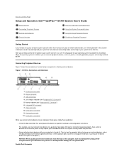
...any devices to avoid possible damage to the system board. Back to Contents Page Setup and Operation: Dell™ OptiPlex™ GX100 System User's Guide Getting Started Security Cable Slot and Padlock Ring Connecting Peripheral Devices Using the System ... is installed, you connect external devices to a particular input/output (I /O Ports, Connectors, and Indicators 1 Parallel port connector 2 Mouse connector 3 USB connectors 4 Link integrity indicator (see "Integrated NIC Connector") 5 Activity indicator (see "Integrated NIC Connector") 6 Integrated NIC connector 7 Video connector ...
...any devices to avoid possible damage to the system board. Back to Contents Page Setup and Operation: Dell™ OptiPlex™ GX100 System User's Guide Getting Started Security Cable Slot and Padlock Ring Connecting Peripheral Devices Using the System ... is installed, you connect external devices to a particular input/output (I /O Ports, Connectors, and Indicators 1 Parallel port connector 2 Mouse connector 3 USB connectors 4 Link integrity indicator (see "Integrated NIC Connector") 5 Activity indicator (see "Integrated NIC Connector") 6 Integrated NIC connector 7 Video connector ...
User Guide
Page 82
... default designation of your hardware, you move the mouse. USB Connectors Your system contains two Universal Serial Bus (USB) connectors for attaching a video graphics array (VGA)-compatible monitor to your computer. The NIC connector on your Dell ResourceCD for these integrated serial ports are used in a...System Setup. If you have the Microsoft® Windows® 98, Windows 95, or Windows NT® 4.0 operating system, Dell already installed the necessary mouse drivers on the computer's back panel has the following indicators (see the documentation that it lights up ...
... default designation of your hardware, you move the mouse. USB Connectors Your system contains two Universal Serial Bus (USB) connectors for attaching a video graphics array (VGA)-compatible monitor to your computer. The NIC connector on your Dell ResourceCD for these integrated serial ports are used in a...System Setup. If you have the Microsoft® Windows® 98, Windows 95, or Windows NT® 4.0 operating system, Dell already installed the necessary mouse drivers on the computer's back panel has the following indicators (see the documentation that it lights up ...
User Guide
Page 91
... option determines the I /O address 3E8h). l Mouse Port l Serial Port 1 and Serial Port 2 l Parallel Port l IDE Drive Interface l Diskette Interface l USB Emulation l PC Speaker l Primary Video Controller l Video DAC Snoop Press to configure these options to Auto (the default) to automatically configure a port, to a ...: l COM1 (input/output [I/O] address 3F8h), which shares IRQ3 with the device. NOTE: You cannot set to press at the Dell logo screen during system boot. DMA Channel This option determines the direct memory access (DMA) channel used by the parallel port and appears...
... option determines the I /O address 3E8h). l Mouse Port l Serial Port 1 and Serial Port 2 l Parallel Port l IDE Drive Interface l Diskette Interface l USB Emulation l PC Speaker l Primary Video Controller l Video DAC Snoop Press to configure these options to Auto (the default) to automatically configure a port, to a ...: l COM1 (input/output [I/O] address 3F8h), which shares IRQ3 with the device. NOTE: You cannot set to press at the Dell logo screen during system boot. DMA Channel This option determines the direct memory access (DMA) channel used by the parallel port and appears...

User Guide
Page 92
...this setting is activated, the rightmost bank of the boot routine, the system first checks for EIDE CD-ROM and EIDE tape drives. Set USB Emulation to Off if you do not need to change to any diskette drives and tape drives using a PS/2-compatible keyboard and mouse. A... turns off the integrated EIDE interface when necessary to use by the operating system. When On is selected, the system BIOS controls USB keyboards and mice until a USB driver is selected, Auto (whereby the system turns off the integrated diskette/tape drive controller; Normally you are using a video expansion...
...this setting is activated, the rightmost bank of the boot routine, the system first checks for EIDE CD-ROM and EIDE tape drives. Set USB Emulation to Off if you do not need to change to any diskette drives and tape drives using a PS/2-compatible keyboard and mouse. A... turns off the integrated EIDE interface when necessary to use by the operating system. When On is selected, the system BIOS controls USB keyboards and mice until a USB driver is selected, Auto (whereby the system turns off the integrated diskette/tape drive controller; Normally you are using a video expansion...
User Guide
Page 101
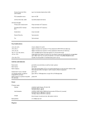
... EIDE hard-disk drive Secondary EIDE hard-disk drive Diskette drive Remote Wake Up Fan 6-pin mini-Deutsche Industrie Norm (DIN) 6-pin mini-DIN two USB-compliant connectors 40-pin connector on PCI local bus 40-pin connector on PCI local bus 34-pin connector 3-pin connector 3-pin connector Key Combinations...
... EIDE hard-disk drive Secondary EIDE hard-disk drive Diskette drive Remote Wake Up Fan 6-pin mini-Deutsche Industrie Norm (DIN) 6-pin mini-DIN two USB-compliant connectors 40-pin connector on PCI local bus 40-pin connector on PCI local bus 34-pin connector 3-pin connector 3-pin connector Key Combinations...
Service Manual
Page 11
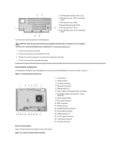
...) 4 Remote Wakeup header (WOL) 5 PCI expansion slot 1 (PCI1) 6 PCI expansion slot 2 (PCI2; System Board Components 1 NIC connector 2 Video connector 3 Fan power connector 4 Serial port 2 connector 5 USB connectors (2) 6 Mouse (upper) and keyboard (lower) connectors 7 Parallel port (upper) and serial port 1 (lower) connectors 8 System board jumpers 9 Riser board connector 10 EIDE1 connector 11...
...) 4 Remote Wakeup header (WOL) 5 PCI expansion slot 1 (PCI1) 6 PCI expansion slot 2 (PCI2; System Board Components 1 NIC connector 2 Video connector 3 Fan power connector 4 Serial port 2 connector 5 USB connectors (2) 6 Mouse (upper) and keyboard (lower) connectors 7 Parallel port (upper) and serial port 1 (lower) connectors 8 System board jumpers 9 Riser board connector 10 EIDE1 connector 11...
Service Manual
Page 12
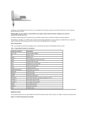
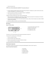
...example of two or more pins on your system board, and it down over the pins. Figure 19. 32-Bit PCI Expansion Card Example Dell shipped your computer with a PSWD jumper installed, meaning that password features for connectors and sockets on a circuit board. Jumper pins are small ... may occur. Otherwise, damage to as LPT1 Main power input connector 3.3-V power input connector Riser board connector Serial port connectors USB connectors Expansion Cards The low-profile GX100 chassis can accommodate three 32-bit PCI expansion cards. The wire connects the pins and creates a circuit.
...example of two or more pins on your system board, and it down over the pins. Figure 19. 32-Bit PCI Expansion Card Example Dell shipped your computer with a PSWD jumper installed, meaning that password features for connectors and sockets on a circuit board. Jumper pins are small ... may occur. Otherwise, damage to as LPT1 Main power input connector 3.3-V power input connector Riser board connector Serial port connectors USB connectors Expansion Cards The low-profile GX100 chassis can accommodate three 32-bit PCI expansion cards. The wire connects the pins and creates a circuit.
Service Manual
Page 32
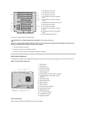
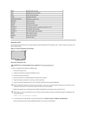
... slot 2 (PCI2) 3 PCI expansion slot 3 (PCI3) 4 PCI expansion slot 4 (PCI4; Figure 24. System Board Components 1 NIC connector 2 Video connector 3 Fan power connector 4 Serial port 2 connector 5 USB connectors (2) 6 Keyboard (upper) and mouse (lower) connectors 7 Parallel port (upper) and serial port 1 (lower) connectors 8 System board jumper 9 Riser board connector 10 EIDE1 connector 11...
... slot 2 (PCI2) 3 PCI expansion slot 3 (PCI3) 4 PCI expansion slot 4 (PCI4; Figure 24. System Board Components 1 NIC connector 2 Video connector 3 Fan power connector 4 Serial port 2 connector 5 USB connectors (2) 6 Keyboard (upper) and mouse (lower) connectors 7 Parallel port (upper) and serial port 1 (lower) connectors 8 System board jumper 9 Riser board connector 10 EIDE1 connector 11...
Service Manual
Page 33
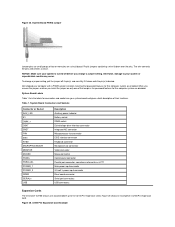
... sometimes referred to as LPT1 Main power input connector 3.3-volt V power input connector Riser board connector Serial port connectors USB connectors Expansion Cards The mini tower GX100 chassis can accommodate up to your system board and gives a brief description of a 32-bit PCI expansion card. ...(s) and carefully fit it down over the pins. Otherwise, damage to five 32-bit PCI expansion cards. Figure 25. Table 1. Dell shipped your computer with a PSWD jumper installed, meaning that password features for connectors and sockets on your system or unpredictable results may ...
... sometimes referred to as LPT1 Main power input connector 3.3-volt V power input connector Riser board connector Serial port connectors USB connectors Expansion Cards The mini tower GX100 chassis can accommodate up to your system board and gives a brief description of a 32-bit PCI expansion card. ...(s) and carefully fit it down over the pins. Otherwise, damage to five 32-bit PCI expansion cards. Figure 25. Table 1. Dell shipped your computer with a PSWD jumper installed, meaning that password features for connectors and sockets on your system or unpredictable results may ...
Service Manual
Page 51
.... 3. Riser Board Figure 19. Remove the expansion cards installed in "Precautionary Measures." 2. System Board Components 1 NIC connector 2 Video connector 3 Fan power connector 4 Serial port 2 connector 5 USB connectors (2) System Board Components The subsections that has two PCI expansion-card connectors (see Figure 18). Locate the securing lever and rotate the lever upward...
.... 3. Riser Board Figure 19. Remove the expansion cards installed in "Precautionary Measures." 2. System Board Components 1 NIC connector 2 Video connector 3 Fan power connector 4 Serial port 2 connector 5 USB connectors (2) System Board Components The subsections that has two PCI expansion-card connectors (see Figure 18). Locate the securing lever and rotate the lever upward...
Service Manual
Page 53
... strap as LPT1 Main power input connector 3.3-volt (V) power input connector Riser board connector Serial port connectors USB connectors Expansion Cards The small-form-factor GX100 chassis can accommodate up : ALERT! Grasp the card by its outside corners, and ease it out of...will cause the following steps. 1. ENET FAN IDEn KYBD MICROPROCESSOR MONITOR MOUSE PANEL PARALLEL POWER_1 POWER_2 RISER SERIALn USB Integrated NIC connector Microprocessor fan connector EIDE interface connector Keyboard connector Microprocessor connector Video connector Mouse connector Control panel connector Parallel...
... strap as LPT1 Main power input connector 3.3-volt (V) power input connector Riser board connector Serial port connectors USB connectors Expansion Cards The small-form-factor GX100 chassis can accommodate up : ALERT! Grasp the card by its outside corners, and ease it out of...will cause the following steps. 1. ENET FAN IDEn KYBD MICROPROCESSOR MONITOR MOUSE PANEL PARALLEL POWER_1 POWER_2 RISER SERIALn USB Integrated NIC connector Microprocessor fan connector EIDE interface connector Keyboard connector Microprocessor connector Video connector Mouse connector Control panel connector Parallel...

