User Guide
Page 19
... documentation that accompanied the drive to Contents Page Diskette, Tape, and CD-ROM Drives: Dell™ OptiPlex™ GX100 System User's Guide Installing a CD-ROM Drive in a Small-Form-Factor Chassis Installing a Diskette, Tape, or CD-ROM Drive in a Low-Profile Chassis Installing a Diskette, Tape, or CD-ROM Drive in a Mini Tower Chassis Connecting Drives...
... documentation that accompanied the drive to Contents Page Diskette, Tape, and CD-ROM Drives: Dell™ OptiPlex™ GX100 System User's Guide Installing a CD-ROM Drive in a Small-Form-Factor Chassis Installing a Diskette, Tape, or CD-ROM Drive in a Low-Profile Chassis Installing a Diskette, Tape, or CD-ROM Drive in a Mini Tower Chassis Connecting Drives...
User Guide
Page 20
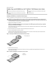
...and peripherals to verify that your computer system. Verify that the drive is configured for your system works correctly by running the Dell Diagnostics. Check the documentation that accompanied the drive. 2. If you are installing an enhanced integrated drive electronics (EIDE) drive, ... computer. See "Primary Drive n and Secondary Drive n" for the cable select setting. Remove the computer cover as instructed in a low-profile chassis, perform the following steps. Attaching Cables to Auto. Change any peripherals, disconnect them on the drive. Facing the front of ...
...and peripherals to verify that your computer system. Verify that the drive is configured for your system works correctly by running the Dell Diagnostics. Check the documentation that accompanied the drive. 2. If you are installing an enhanced integrated drive electronics (EIDE) drive, ... computer. See "Primary Drive n and Secondary Drive n" for the cable select setting. Remove the computer cover as instructed in a low-profile chassis, perform the following steps. Attaching Cables to Auto. Change any peripherals, disconnect them on the drive. Facing the front of ...
User Guide
Page 26
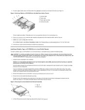
...4). The PCI riser board provides three PCI expansion card slots. Low-Profile Chassis PCI Riser Board (Standard) Dell recommends this step due to Contents Page Expansion Cards: Dell™ OptiPlex™ GX100 System User's Guide Overview Riser Boards Installing an Expansion Card Removing... an Expansion Card Overview OptiPlex GX100 systems can accommodate a mix of 32-bit Peripheral Component Interconnect (PCI) expansion cards...
...4). The PCI riser board provides three PCI expansion card slots. Low-Profile Chassis PCI Riser Board (Standard) Dell recommends this step due to Contents Page Expansion Cards: Dell™ OptiPlex™ GX100 System User's Guide Overview Riser Boards Installing an Expansion Card Removing... an Expansion Card Overview OptiPlex GX100 systems can accommodate a mix of 32-bit Peripheral Component Interconnect (PCI) expansion cards...
User Guide
Page 27
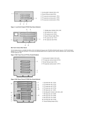
Low-Profile Chassis PCI/ISA Riser Board (Optional) 1 Standby power indicator (AUX_LED) 2 ISA expansion slot 1 (ISA1) 3 ISA expansion slot 2 (ISA2) 4 Remote Wakeup header (WOL) 5 PCI expansion slot 1 (...
Low-Profile Chassis PCI/ISA Riser Board (Optional) 1 Standby power indicator (AUX_LED) 2 ISA expansion slot 1 (ISA1) 3 ISA expansion slot 2 (ISA2) 4 Remote Wakeup header (WOL) 5 PCI expansion slot 1 (...
User Guide
Page 28
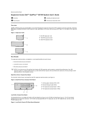
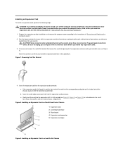
...the card into the corresponding card guide on configuring the card, making internal connections, or otherwise customizing it for the smallform-factor, low-profile, and mini tower chassis, respectively). Removing the Filler Bracket 4. Figure 8. Installing an Expansion Card in a Small-Form-Factor ... installation, and remove the computer cover according to the instructions in this procedure. b. Installing an Expansion Card in a Low-Profile Chassis Insert the expansion card into the expansion-card connector. c. CAUTION: Some network cards automatically start up the system ...
...the card into the corresponding card guide on configuring the card, making internal connections, or otherwise customizing it for the smallform-factor, low-profile, and mini tower chassis, respectively). Removing the Filler Bracket 4. Figure 8. Installing an Expansion Card in a Small-Form-Factor ... installation, and remove the computer cover according to the instructions in this procedure. b. Installing an Expansion Card in a Low-Profile Chassis Insert the expansion card into the expansion-card connector. c. CAUTION: Some network cards automatically start up the system ...

User Guide
Page 35
... from the chassis. Figure 1. Back to Contents Page Hard-Disk Drives: Dell™ OptiPlex™ GX100 System User's Guide General Information About EIDE Hard-Disk Drives Installing an EIDE Hard-Disk Drive in a Low-Profile Chassis Installing an EIDE Hard-Disk Drive in a Small-Form-Factor Chassis ...Installing an EIDE Hard-Disk Drive in a Mini Tower Chassis General Information About EIDE Hard-Disk Drives The small form-factor and low-profile chassis support a single enhanced integrated drive electronics (EIDE) hard-disk drive in the 1-inch (lower) drive bay labeled "HD1"; The...
... from the chassis. Figure 1. Back to Contents Page Hard-Disk Drives: Dell™ OptiPlex™ GX100 System User's Guide General Information About EIDE Hard-Disk Drives Installing an EIDE Hard-Disk Drive in a Low-Profile Chassis Installing an EIDE Hard-Disk Drive in a Small-Form-Factor Chassis ...Installing an EIDE Hard-Disk Drive in a Mini Tower Chassis General Information About EIDE Hard-Disk Drives The small form-factor and low-profile chassis support a single enhanced integrated drive electronics (EIDE) hard-disk drive in the 1-inch (lower) drive bay labeled "HD1"; The...
User Guide
Page 37
... cover. Check all connectors to be certain that came with pin 1 on the system board, see Figure 5). Test the hard-disk drive by running the Dell Diagnostics. 16. Then reconnect your computer and peripherals to your operating system on the system board. After you just installed is not already connected, connect... system. 13. Turn on the back of the drive, and connect an EIDE cable to your operating system. Installing an EIDE Hard-Disk Drive in a Low-Profile Chassis To install an EIDE hard-disk drive in...
... cover. Check all connectors to be certain that came with pin 1 on the system board, see Figure 5). Test the hard-disk drive by running the Dell Diagnostics. 16. Then reconnect your computer and peripherals to your operating system on the system board. After you just installed is not already connected, connect... system. 13. Turn on the back of the drive, and connect an EIDE cable to your operating system. Installing an EIDE Hard-Disk Drive in a Low-Profile Chassis To install an EIDE hard-disk drive in...
User Guide
Page 46
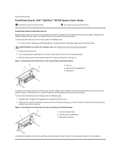
... two ringtabs (see "Safety First-For You and Your Computer." 2. Back to Contents Page Front-Panel Inserts: Dell™ OptiPlex™ GX100 System User's Guide Low-Profile Chassis Front-Panel Inserts Mini Tower Chassis Front-Panel Inserts Low-Profile Chassis Front-Panel Inserts Empty drive bays contain a front-panel insert to protect the inside of the computer...
... two ringtabs (see "Safety First-For You and Your Computer." 2. Back to Contents Page Front-Panel Inserts: Dell™ OptiPlex™ GX100 System User's Guide Low-Profile Chassis Front-Panel Inserts Mini Tower Chassis Front-Panel Inserts Low-Profile Chassis Front-Panel Inserts Empty drive bays contain a front-panel insert to protect the inside of the computer...
User Guide
Page 48
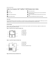
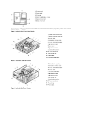
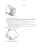
...you work inside the computer. Low-Profile Chassis Orientation View 1 System board 2 Hard-disk drive 3 Power supply 4 Externally accessible drive bays Figure 3. Mini Tower Chassis Orientation View Back to Contents Page Inside Your Computer: Dell™ OptiPlex™ GX100 System User's Guide Overview ... Tower Chassis Only) Removing and Replacing the Expansion-Card Cage Overview This section describes the inside of the small-form-factor, low-profile, and mini tower chassis, respectively, to use before you perform an upgrade procedure. Small-Form-Factor Chassis Orientation View 1 ...
...you work inside the computer. Low-Profile Chassis Orientation View 1 System board 2 Hard-disk drive 3 Power supply 4 Externally accessible drive bays Figure 3. Mini Tower Chassis Orientation View Back to Contents Page Inside Your Computer: Dell™ OptiPlex™ GX100 System User's Guide Overview ... Tower Chassis Only) Removing and Replacing the Expansion-Card Cage Overview This section describes the inside of the small-form-factor, low-profile, and mini tower chassis, respectively, to use before you perform an upgrade procedure. Small-Form-Factor Chassis Orientation View 1 ...
User Guide
Page 49
Inside the Low-Profile Chassis 1 Diskette drive in upper bay 2 Diskette drive interface cable 3 Hard-disk drive interface cable 4 Hard-disk drive 5 Chassis intrusion switch 6 Expansion-card cage 7 Expansion-... board 2 Power supply 3 Drive cage 4 Internal hard-disk drive bracket 5 Expansion-card cage 6 Bottom of computer Figure 4, Figure 5, and Figure 6 show the small-form-factor, low-profile, and mini tower chassis, respectively, with the cover removed.
Inside the Low-Profile Chassis 1 Diskette drive in upper bay 2 Diskette drive interface cable 3 Hard-disk drive interface cable 4 Hard-disk drive 5 Chassis intrusion switch 6 Expansion-card cage 7 Expansion-... board 2 Power supply 3 Drive cage 4 Internal hard-disk drive bracket 5 Expansion-card cage 6 Bottom of computer Figure 4, Figure 5, and Figure 6 show the small-form-factor, low-profile, and mini tower chassis, respectively, with the cover removed.

User Guide
Page 53
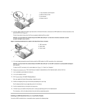
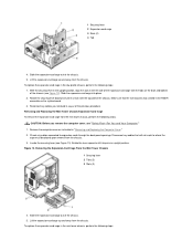
... placed upon removal from the chassis. 2. Figure 11. Locate the securing lever (see Figure 11). Removing the Expansion-Card Cage From the Low-Profile Chassis Removing the Expansion-Card Cage From the Small-Form-Factor Chassis 1 Securing lever 2 Expansion card cage 3 Tab 4 Hook 4. Remove... cables that will not reach to expansion cards through the back-panel openings. Lift the expansion-card cage up and away from the low-profile chassis, perform the following steps: 1. Rotate the securing lever downward until it is fully seated in "Removing and Replacing the Computer...
... placed upon removal from the chassis. 2. Figure 11. Locate the securing lever (see Figure 11). Removing the Expansion-Card Cage From the Low-Profile Chassis Removing the Expansion-Card Cage From the Small-Form-Factor Chassis 1 Securing lever 2 Expansion card cage 3 Tab 4 Hook 4. Remove... cables that will not reach to expansion cards through the back-panel openings. Lift the expansion-card cage up and away from the low-profile chassis, perform the following steps: 1. Rotate the securing lever downward until it is fully seated in "Removing and Replacing the Computer...
User Guide
Page 54
... Cage To remove the expansion-card cage from the chassis. 3. Locate the securing lever (see Figure 12). To replace the expansion-card cage in the low-profile chassis, perform the following steps: Slide the expansion-card cage into place. 2. Make sure that will not reach to expansion cards through the back-panel...
... Cage To remove the expansion-card cage from the chassis. 3. Locate the securing lever (see Figure 12). To replace the expansion-card cage in the low-profile chassis, perform the following steps: Slide the expansion-card cage into place. 2. Make sure that will not reach to expansion cards through the back-panel...
User Guide
Page 57
Back to Contents Page Internal Components: Dell™ OptiPlex™ GX100 System User's Guide Overview Troubleshooting Expansion Cards Safety First-For You and Your Computer Troubleshooting System Memory Removing and Replacing the Computer ...the sequence indicated: 1. l Read the safety instructions in Dell documentation. Turn off your computer and peripherals, and observe the caution for your computer is safe-if you remove the computer cover. While working inside your small form-factor or low-profile chassis has an optional stand attached to work , periodically touch...
Back to Contents Page Internal Components: Dell™ OptiPlex™ GX100 System User's Guide Overview Troubleshooting Expansion Cards Safety First-For You and Your Computer Troubleshooting System Memory Removing and Replacing the Computer ...the sequence indicated: 1. l Read the safety instructions in Dell documentation. Turn off your computer and peripherals, and observe the caution for your computer is safe-if you remove the computer cover. While working inside your small form-factor or low-profile chassis has an optional stand attached to work , periodically touch...
User Guide
Page 58
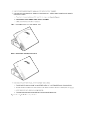
... chassis, skip to swing up toward the front of the chassis. If your computer has a small-form-factor or low-profile chassis, remove the computer cover as follows: a. Figure 3. b. Figure 1. Removing the Low-Profile Computer Cover 4. Removing the Mini Tower Computer Cover Lift the cover off the hooks at the bottom-left -cover release...
... chassis, skip to swing up toward the front of the chassis. If your computer has a small-form-factor or low-profile chassis, remove the computer cover as follows: a. Figure 3. b. Figure 1. Removing the Low-Profile Computer Cover 4. Removing the Mini Tower Computer Cover Lift the cover off the hooks at the bottom-left -cover release...
User Guide
Page 59
Fold cables out of the computer and hold the cover at a slight angle as follows: a. If your computer has a small-form-factor or low-profile chassis, replace the computer cover as shown in Figure 4 and Figure 5. Figure 4. Check all cable connections, especially those that might have come ... has a mini tower chassis, skip to see that the tabs catch the hooks inside the computer's chassis. 3. If your work. c. Replacing the Low-Profile Computer Cover Check to step 4 . Make sure cables are not routed over the drive cage-they do not catch on the computer chassis so that...
Fold cables out of the computer and hold the cover at a slight angle as follows: a. If your computer has a small-form-factor or low-profile chassis, replace the computer cover as shown in Figure 4 and Figure 5. Figure 4. Check all cable connections, especially those that might have come ... has a mini tower chassis, skip to see that the tabs catch the hooks inside the computer's chassis. 3. If your work. c. Replacing the Low-Profile Computer Cover Check to step 4 . Make sure cables are not routed over the drive cage-they do not catch on the computer chassis so that...
User Guide
Page 77
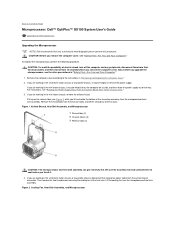
...other precautions in the mini tower chassis, remove the airflow shroud. CAUTION: Before you are working in the small-form-factor chassis or low-profile chassis, it may be helpful to the heat sink. Airflow Shroud, Heat Sink Assembly, and Microprocessor 1 Shroud tabs (2) 2 Chassis ... the following procedure. If you touch it may be helpful to Contents Page Microprocessor: Dell™ OptiPlex™ GX100 System User's Guide Upgrading the Microprocessor Upgrading the Microprocessor NOTE: Dell recommends that only a technically knowledgeable person perform this procedure.
...other precautions in the mini tower chassis, remove the airflow shroud. CAUTION: Before you are working in the small-form-factor chassis or low-profile chassis, it may be helpful to the heat sink. Airflow Shroud, Heat Sink Assembly, and Microprocessor 1 Shroud tabs (2) 2 Chassis ... the following procedure. If you touch it may be helpful to Contents Page Microprocessor: Dell™ OptiPlex™ GX100 System User's Guide Upgrading the Microprocessor Upgrading the Microprocessor NOTE: Dell recommends that only a technically knowledgeable person perform this procedure.

User Guide
Page 80
... the new microprocessor is operating correctly. The shroud should engage the top of installed microprocessor. NOTE: After you are working in a small-form-factor or low-profile chassis system, replace the cooling fan on top of the new microprocessor and automatically changes the system configuration information in System Setup, reset the chassis... on the pair of tabs on the sides of the fan and between the fan and the power supply bracket on the right. Run the Dell Diagnostics to Enabled, Enabled-Silent, or Disabled.
... the new microprocessor is operating correctly. The shroud should engage the top of installed microprocessor. NOTE: After you are working in a small-form-factor or low-profile chassis system, replace the cooling fan on top of the new microprocessor and automatically changes the system configuration information in System Setup, reset the chassis... on the pair of tabs on the sides of the fan and between the fan and the power supply bracket on the right. Run the Dell Diagnostics to Enabled, Enabled-Silent, or Disabled.

User Guide
Page 84
... the padlock ring to remove the computer cover for installing this process may be hung. Complete instructions for the small-form-factor chassis or the low-profile chassis. Before purchasing such a device, make sure it works with the device. The small-form-factor chassis has a padlock ring that future intrusions are usually...
... the padlock ring to remove the computer cover for installing this process may be hung. Complete instructions for the small-form-factor chassis or the low-profile chassis. Before purchasing such a device, make sure it works with the device. The small-form-factor chassis has a padlock ring that future intrusions are usually...
User Guide
Page 100
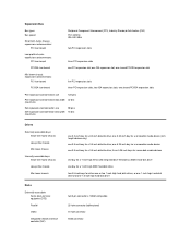
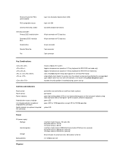
... width (maximum) 98 pins 16 bits Drives Externally accessible bays: Small-form-factor chassis Low-profile chassis Mini tower chassis Internally accessible bays: Small-form-factor chassis Low-profile chassis Mini tower chassis Ports Externally accessible: Serial (data terminal equipment DTE) Parallel Video ...board Peripheral Component Interconnect (PCI), Industry-Standard Architecture (ISA) PCI: 33 MHz ISA: 8.33 MHz two PCI expansion slots Low-profile chassis expansion-card connectors: PCI riser board three PCI expansion slots PCI/ISA riser board one ISA expansion slot; one PCI ...
... width (maximum) 98 pins 16 bits Drives Externally accessible bays: Small-form-factor chassis Low-profile chassis Mini tower chassis Internally accessible bays: Small-form-factor chassis Low-profile chassis Mini tower chassis Ports Externally accessible: Serial (data terminal equipment DTE) Parallel Video ...board Peripheral Component Interconnect (PCI), Industry-Standard Architecture (ISA) PCI: 33 MHz ISA: 8.33 MHz two PCI expansion slots Low-profile chassis expansion-card connectors: PCI riser board three PCI expansion slots PCI/ISA riser board one ISA expansion slot; one PCI ...
User Guide
Page 101
orange LED for 10-Mb operation; low-profile chassis: 808 BTU/hr (nominal); low-profile chassis: 145 W; mini tower chassis: 200 W small-form-factor chassis: 808 British thermal units (BTU)/hour (hr) (nominal); mini tower chassis: 913 BTU/hr (nominal) ...
orange LED for 10-Mb operation; low-profile chassis: 808 BTU/hr (nominal); low-profile chassis: 145 W; mini tower chassis: 200 W small-form-factor chassis: 808 British thermal units (BTU)/hour (hr) (nominal); mini tower chassis: 913 BTU/hr (nominal) ...


