Setup and Features Information Tech Sheet
Page 1
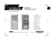
...; activity light (optional) 4 diagnostic lights (4) 5 power button, power light 6 optical drive 7 optical drive eject button 8 optical drive filler panel 9 flex bay 10 USB 2.0 connectors (4) 11 headphone connector 12 microphone connector 13 padlock ring 14 security cable slot 15 power cable connector 16 back panel connectors 17 expansion card slots (4) 18 power supply diagnostic button 19 power supply diagnostic light Models: Mini Tower: DCSM1F; and Small Form Factor: DCCY1F series February 2010 Y991Mam1.fm Page 1 Tuesday, January 19, 2010 4:39 PM Dell™ OptiPlex™ 980 Setup and...
...; activity light (optional) 4 diagnostic lights (4) 5 power button, power light 6 optical drive 7 optical drive eject button 8 optical drive filler panel 9 flex bay 10 USB 2.0 connectors (4) 11 headphone connector 12 microphone connector 13 padlock ring 14 security cable slot 15 power cable connector 16 back panel connectors 17 expansion card slots (4) 18 power supply diagnostic button 19 power supply diagnostic light Models: Mini Tower: DCSM1F; and Small Form Factor: DCCY1F series February 2010 Y991Mam1.fm Page 1 Tuesday, January 19, 2010 4:39 PM Dell™ OptiPlex™ 980 Setup and...
Setup and Features Information Tech Sheet
Page 2
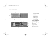
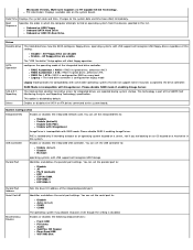
Front and Back View 1 11 10 9 8 7 2 6 3 5 4 12 13 18 17 16 1 power button, power light 2 optical drive 3 optical drive eject button 4 USB 2.0 connectors (2) 5 microphone connector 6 headphone connector 7 flex bay 8 drive activity light 9 network activity light 10 Wi-Fi activity light (optional) 11 diagnostic lights (4) 12 power supply diagnostic button 13 power supply diagnostic light 14 14 padlock ring 15 security cable slot 15 16 power cable connector 17 back panel connectors 18 expansion card slots (4) Y991Mam1.fm Page 2 Tuesday, January 19, 2010 4:39 PM ...
Front and Back View 1 11 10 9 8 7 2 6 3 5 4 12 13 18 17 16 1 power button, power light 2 optical drive 3 optical drive eject button 4 USB 2.0 connectors (2) 5 microphone connector 6 headphone connector 7 flex bay 8 drive activity light 9 network activity light 10 Wi-Fi activity light (optional) 11 diagnostic lights (4) 12 power supply diagnostic button 13 power supply diagnostic light 14 14 padlock ring 15 security cable slot 15 16 power cable connector 17 back panel connectors 18 expansion card slots (4) Y991Mam1.fm Page 2 Tuesday, January 19, 2010 4:39 PM ...
Setup and Features Information Tech Sheet
Page 3
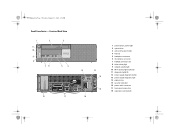
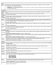
Front and Back View 1 11 10 9 8 2 76 3 5 4 18 17 12 13 14 15 16 1 power button, power light 2 optical drive 3 optical drive eject button 4 flex bay 5 headphone connector 6 microphone connector 7 USB 2.0 connectors (2) 8 drive activity light 9 network activity light 10 Wi-Fi activity light (optional) 11 diagnostic lights (4) 12 power supply diagnostic button 13 power supply diagnostic light 14 padlock ring 15 security cable slot 16 power cable connector 17 back panel connectors 18 expansion card slots (2) Y991Mam1.fm Page 3 Tuesday, January 19, 2010 4:39 PM Small Form Factor -
Front and Back View 1 11 10 9 8 2 76 3 5 4 18 17 12 13 14 15 16 1 power button, power light 2 optical drive 3 optical drive eject button 4 flex bay 5 headphone connector 6 microphone connector 7 USB 2.0 connectors (2) 8 drive activity light 9 network activity light 10 Wi-Fi activity light (optional) 11 diagnostic lights (4) 12 power supply diagnostic button 13 power supply diagnostic light 14 padlock ring 15 security cable slot 16 power cable connector 17 back panel connectors 18 expansion card slots (2) Y991Mam1.fm Page 3 Tuesday, January 19, 2010 4:39 PM Small Form Factor -
Setup and Features Information Tech Sheet
Page 6
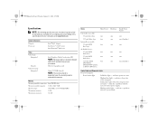
... Internally accessible: 3.5-inch SATA drive bays two one Available devices: 2.5-inch SATA hard drives two two 3.5-inch SATA hard drives two one 5.25-inch SATA two one DVD-ROM, DVD/CD-RW Combo, or DVD+/-RW drives Small Form Factor one one (slimline) one two one one (slimline) Control Lights and Diagnostic Lights Front of the computer. Solid amber light (when the computer does not start) - PCI-E x16 graphics card Upto 1759 MB (shared) NOTE: The memory...
... Internally accessible: 3.5-inch SATA drive bays two one Available devices: 2.5-inch SATA hard drives two two 3.5-inch SATA hard drives two one 5.25-inch SATA two one DVD-ROM, DVD/CD-RW Combo, or DVD+/-RW drives Small Form Factor one one (slimline) one two one one (slimline) Control Lights and Diagnostic Lights Front of the computer. Solid amber light (when the computer does not start) - PCI-E x16 graphics card Upto 1759 MB (shared) NOTE: The memory...
Setup and Features Information Tech Sheet
Page 7
... test button. Orange light - Yellow light - When the system's power supply voltage is not detecting a physical connection to the power connector (at support.dell.com/manuals. A good connection exists between the network and the computer. Off (no light) - Coin-cell battery 3V CR2032 lithium coin cell adapter Control Lights and Diagnostic Lights (continued) Power supply light Green light - NOTE: You can test the health of computer Link integrity light on and is turned on integrated network adapter Green light - Blue light - Network activity light...
... test button. Orange light - Yellow light - When the system's power supply voltage is not detecting a physical connection to the power connector (at support.dell.com/manuals. A good connection exists between the network and the computer. Off (no light) - Coin-cell battery 3V CR2032 lithium coin cell adapter Control Lights and Diagnostic Lights (continued) Power supply light Green light - NOTE: You can test the health of computer Link integrity light on and is turned on integrated network adapter Green light - Blue light - Network activity light...
Technical Guidebook
Page 2
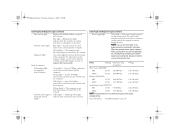
... System Manageability Modes, System Monitoring Options Memory Drives and Removable Storage System Board Connectors, Graphics/Video Controller External Ports/Connectors Communications-Integrated LAN, Wireless, Audio and Speakers, Keyboard and Mouse, Security Security, Service and Support, Software, System Accessories DETAILED ENGINEERING SPECIFICATIONS System Dimensions (Physical) System Board Connector Maximum Allowable Dimensions System Level Environmental and Operating Conditions Power, Compliance Audio Communications Graphics/Video Controller Hard Drives Optical Drive BIOS Defaults Chassis...
... System Manageability Modes, System Monitoring Options Memory Drives and Removable Storage System Board Connectors, Graphics/Video Controller External Ports/Connectors Communications-Integrated LAN, Wireless, Audio and Speakers, Keyboard and Mouse, Security Security, Service and Support, Software, System Accessories DETAILED ENGINEERING SPECIFICATIONS System Dimensions (Physical) System Board Connector Maximum Allowable Dimensions System Level Environmental and Operating Conditions Power, Compliance Audio Communications Graphics/Video Controller Hard Drives Optical Drive BIOS Defaults Chassis...
Technical Guidebook
Page 3
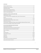
DESKTOP COMPUTER (DT) VIEW Front and Back View FRONT VIEW 1 Drive activity light 4 Network activity light 2 2 Wi-Fi activity light 3 Network activity light 1 5 DVD drive bay 6 USB 2.0 connectors (2) 7 External power button connector 8 Diagnostic Lights (4) 9 Power button, power light BACK VIEW 10 Power supply diagnostic button 11 Power supply diagnostic light 12 Cover release latch 13 Padlock ring 14 Security cable slot 15 Power cable connector 16 Back panel connectors 17 Expansion card slots (4) OptiPlex XE Technical Guidebook Page 3
DESKTOP COMPUTER (DT) VIEW Front and Back View FRONT VIEW 1 Drive activity light 4 Network activity light 2 2 Wi-Fi activity light 3 Network activity light 1 5 DVD drive bay 6 USB 2.0 connectors (2) 7 External power button connector 8 Diagnostic Lights (4) 9 Power button, power light BACK VIEW 10 Power supply diagnostic button 11 Power supply diagnostic light 12 Cover release latch 13 Padlock ring 14 Security cable slot 15 Power cable connector 16 Back panel connectors 17 Expansion card slots (4) OptiPlex XE Technical Guidebook Page 3
Technical Guidebook
Page 14
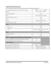
... diagrams section for port/connector locations USB 2.0 DT SFF 2 front, 4 rear, 2 internal 24V Powered USB 2.0 Serial Network Connector (RJ-45) PS/2 Wireless Routing for powered 2 rear 2 rear Optional via add-in card 1 front 1 rear 1 rear Optional via add-in /microphone Line out Risers: (replaces PCI slot and PCIex16 slot on DT system board) Combo full height riser with 1 PCI and 1 PCIe x16 connector Dual full height riser with 2 PCI connectors Add-In Port Cards: 3 Port 12V Powered USB PCI Card 2 Port 12V Powered USB PCI Card 2 Port Powered Serial PCIe x1 card 1 rear 2 rear with optional...
... diagrams section for port/connector locations USB 2.0 DT SFF 2 front, 4 rear, 2 internal 24V Powered USB 2.0 Serial Network Connector (RJ-45) PS/2 Wireless Routing for powered 2 rear 2 rear Optional via add-in card 1 front 1 rear 1 rear Optional via add-in /microphone Line out Risers: (replaces PCI slot and PCIex16 slot on DT system board) Combo full height riser with 1 PCI and 1 PCIe x16 connector Dual full height riser with 2 PCI connectors Add-In Port Cards: 3 Port 12V Powered USB PCI Card 2 Port 12V Powered USB PCI Card 2 Port Powered Serial PCIe x1 card 1 rear 2 rear with optional...
Service Manual
Page 2
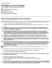
..., not on the cable itself. Damage due to servicing that your work , periodically touch an unpainted metal surface to prevent the cover from being scratched. 2. Back to Contents Page Working on Your Computer Dell™ OptiPlex™ 980 Service Manual-Mini-Tower Before Working Inside Your Computer Recommended Tools Turning Off Your Computer After Working Inside Your Computer Before Working Inside Your Computer Use the following safety guidelines...
..., not on the cable itself. Damage due to servicing that your work , periodically touch an unpainted metal surface to prevent the cover from being scratched. 2. Back to Contents Page Working on Your Computer Dell™ OptiPlex™ 980 Service Manual-Mini-Tower Before Working Inside Your Computer Recommended Tools Turning Off Your Computer After Working Inside Your Computer Before Working Inside Your Computer Use the following safety guidelines...
Service Manual
Page 3
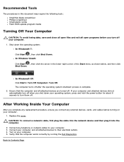
... power button for about 6 seconds to Contents Page Replace the cover. The computer turns off . Connect any external devices, cards, and cables before you turn them off after the operating system shutdown process is complete. 2. Ensure that the computer works correctly by running the Dell Diagnostics. Recommended Tools The procedures in the lower-right corner of the Start menu as shown below, and then click Shut Down. In Windows Vista...
... power button for about 6 seconds to Contents Page Replace the cover. The computer turns off . Connect any external devices, cards, and cables before you turn them off after the operating system shutdown process is complete. 2. Ensure that the computer works correctly by running the Dell Diagnostics. Recommended Tools The procedures in the lower-right corner of the Start menu as shown below, and then click Shut Down. In Windows Vista...
Service Manual
Page 14
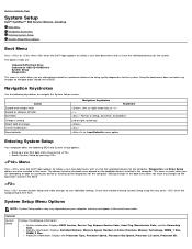
...980 Service Manual-Desktop Boot Menu Navigation Keystrokes Entering System Setup System Setup Menu Options Boot Menu Press or when the Dell™ logo appears to initiate a one -time boot menu with a list of the valid boot devices for the computer. Making changes in the boot menu does not make changes to user-definable settings. System Setup Menu Options NOTE: System Setup options may vary depending on the bootable devices installed in the BIOS. The options listed are: Onboard SATA Hard Drive Onboard or USB CD-ROM Drive System Setup Diagnostics This menu is useful...
...980 Service Manual-Desktop Boot Menu Navigation Keystrokes Entering System Setup System Setup Menu Options Boot Menu Press or when the Dell™ logo appears to initiate a one -time boot menu with a list of the valid boot devices for the computer. Making changes in the boot menu does not make changes to user-definable settings. System Setup Menu Options NOTE: System Setup options may vary depending on the bootable devices installed in the BIOS. The options listed are: Onboard SATA Hard Drive Onboard or USB CD-ROM Drive System Setup Diagnostics This menu is useful...
Service Manual
Page 15
... USB PCI slots Audio OptiPlex ON Reader Rear Quad USB WiFi NIC Slot RAID Autodetect / AHCI = RAID if signed drives, otherwise AHCI RAID Autodetect / ATA= RAID if signed drives, otherwise ATA RAID On / ATA= SATA is configured for integrated drives are disable Enable - Identifies and defines the serial port settings. Date/Time Displays the system date and time. All Floppy drive are reported during system startup. configures the operating mode of the integrated parallel port. Please disable RAID mode if enabling Image Server. This field controls whether hard drive errors for RAID...
... USB PCI slots Audio OptiPlex ON Reader Rear Quad USB WiFi NIC Slot RAID Autodetect / AHCI = RAID if signed drives, otherwise AHCI RAID Autodetect / ATA= RAID if signed drives, otherwise ATA RAID On / ATA= SATA is configured for integrated drives are disable Enable - Identifies and defines the serial port settings. Date/Time Displays the system date and time. All Floppy drive are reported during system startup. configures the operating mode of the integrated parallel port. Please disable RAID mode if enabling Image Server. This field controls whether hard drive errors for RAID...
Service Manual
Page 16
...disable the integrated video controller. Some operating systems will have one thread per enabled core is enabled This option is disabled by default. Enable Intel® Virtualization Technology - This option is disabled by default. This option is disabled by default. Password Changes Admin Setup Lockout Password Configuration Enables or disables the user from entering Setup when an Admin password is disabled by default. These fields control the minimum and maximum number of the processor. Changes to 8 characters. If enabled, all cores enable. You can utilize...
...disable the integrated video controller. Some operating systems will have one thread per enabled core is enabled This option is disabled by default. Enable Intel® Virtualization Technology - This option is disabled by default. This option is disabled by default. Password Changes Admin Setup Lockout Password Configuration Enables or disables the user from entering Setup when an Admin password is disabled by default. These fields control the minimum and maximum number of the processor. Changes to 8 characters. If enabled, all cores enable. You can utilize...
Service Manual
Page 17
... does not work if you turn on a power strip or surge protector or if Auto Power On is set . NOTE: When enabled, the fan runs at full speed. Deactivate (default) Activate Clear When TPM Security is set to disabled. CPU XD Support Enables or disables the execute disable mode of your system board. Allows the system to : S1 S3 (default) Fan Control Override Controls the speed of the hard drives connected to Clear, the system setup program clears the owner information stored...
... does not work if you turn on a power strip or surge protector or if Auto Power On is set . NOTE: When enabled, the fan runs at full speed. Deactivate (default) Activate Clear When TPM Security is set to disabled. CPU XD Support Enables or disables the execute disable mode of your system board. Allows the system to : S1 S3 (default) Fan Control Override Controls the speed of the hard drives connected to Clear, the system setup program clears the owner information stored...
Service Manual
Page 18
... certain configurations and tests. Static IP DNS NOTE: You must set Client DHCP to set the "Integrated NIC" control in the "System Configuration" group to Contents Page The default setting is 255.255.255.255 NOTE: To set Client IP you must set to enter the Manageability Engine BIOS Extensions(MEBx) Setup program. Enable F2 = Setup (enabled by default) Enable F12 = Boot menu (enabled by default. Some graphics cards require the SERR Message mechanism be disabled. Image Server...
... certain configurations and tests. Static IP DNS NOTE: You must set Client DHCP to set the "Integrated NIC" control in the "System Configuration" group to Contents Page The default setting is 255.255.255.255 NOTE: To set Client IP you must set to enter the Manageability Engine BIOS Extensions(MEBx) Setup program. Enable F2 = Setup (enabled by default) Enable F12 = Boot menu (enabled by default. Some graphics cards require the SERR Message mechanism be disabled. Image Server...
Service Manual
Page 19
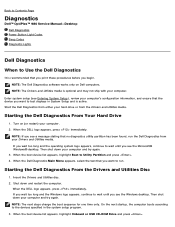
... Entering System Setup), review your computer. Enter system setup (see a message stating that no diagnostics utility partition has been found, run . NOTE: The next steps change the boot sequence for one time only. Turn on Dell computers. Back to Contents Page Diagnostics Dell™ OptiPlex™ 980 Service Manual-Desktop Dell Diagnostics Power Button Light Codes Beep Codes Diagnostic Lights Dell Diagnostics When to Use the Dell Diagnostics It is recommended that you print these procedures before you want to run the Dell Diagnostics from the Drivers and Utilities media...
... Entering System Setup), review your computer. Enter system setup (see a message stating that no diagnostics utility partition has been found, run . NOTE: The next steps change the boot sequence for one time only. Turn on Dell computers. Back to Contents Page Diagnostics Dell™ OptiPlex™ 980 Service Manual-Desktop Dell Diagnostics Power Button Light Codes Beep Codes Diagnostic Lights Dell Diagnostics When to Use the Dell Diagnostics It is recommended that you print these procedures before you want to run the Dell Diagnostics from the Drivers and Utilities media...
Service Manual
Page 20
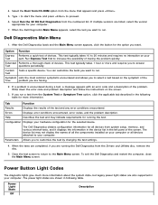
... the Boot from CD-ROM option from the numbered list. When the Dell Diagnostics Main Menu appears, select the test you want to your computer. Errors Displays error conditions encountered, error codes, and the problem description. Parameters Allows you want to increase the possibility of the Tree problem you run a test from the Drivers and Utilities disc, remove the disc. 5. Type 1 to start the menu and press to the Main Menu screen. The Dell Diagnostics obtains configuration information for the selected device...
... the Boot from CD-ROM option from the numbered list. When the Dell Diagnostics Main Menu appears, select the test you want to your computer. Errors Displays error conditions encountered, error codes, and the problem description. Parameters Allows you want to increase the possibility of the Tree problem you run a test from the Drivers and Utilities disc, remove the disc. 5. Type 1 to start the menu and press to the Main Menu screen. The Dell Diagnostics obtains configuration information for the selected device...
Service Manual
Page 23
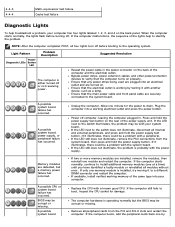
..., install verified working by A possible system board Replace the CPU with a peripheral. Remove all four lights turn off . A possible system board, power supply, or peripheral failure has occurred. Press and hold the power supply test button. If the LED still does not illuminate, the problem is operating normally but a memory power failure has occurred. If the computer starts normally, continue to the switch illuminates, the problem may be corrupt or missing. If the computer boots, add the...
..., install verified working by A possible system board Replace the CPU with a peripheral. Remove all four lights turn off . A possible system board, power supply, or peripheral failure has occurred. Press and hold the power supply test button. If the LED still does not illuminate, the problem is operating normally but a memory power failure has occurred. If the computer starts normally, continue to the switch illuminates, the problem may be corrupt or missing. If the computer boots, add the...
Service Manual
Page 24
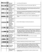
... cards from the power supply unit. A possible USB failure has occurred. Memory modules are installed, remove the modules (see your computer. If available, install a working graphics card into your service manual and restart the computer. failure has occurred. A possible system board failure has occurred. The computer is in a normal on . The diagnostic lights are detected. A possible processor failure has occurred. No memory modules are not lit after the computer successfully boots to the operating...
... cards from the power supply unit. A possible USB failure has occurred. Memory modules are installed, remove the modules (see your computer. If available, install a working graphics card into your service manual and restart the computer. failure has occurred. A possible system board failure has occurred. The computer is in a normal on . The diagnostic lights are detected. A possible processor failure has occurred. No memory modules are not lit after the computer successfully boots to the operating...
Service Manual
Page 25
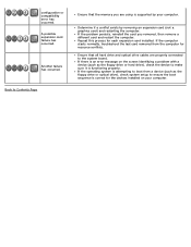
... is supported by removing an expansion card (not a graphics card) and restarting the computer. If the operating system is correct for resource conflicts. Repeat this process for each expansion card installed. A possible expansion card failure has occurred. configuration or compatibility error has occurred. Another failure has occurred. Back to boot from the computer for the devices installed on the screen identifying a problem with a device (such as the floppy drive or optical drive...
... is supported by removing an expansion card (not a graphics card) and restarting the computer. If the operating system is correct for resource conflicts. Repeat this process for each expansion card installed. A possible expansion card failure has occurred. configuration or compatibility error has occurred. Another failure has occurred. Back to boot from the computer for the devices installed on the screen identifying a problem with a device (such as the floppy drive or optical drive...


