
Owner's Manual
Page 3
......13 Removing the VESA Mount Bracket...13 Installing the VESA Mount Bracket...14 Removing the Power and On-Screen Display (OSD) Buttons Board 14 Installing the Power and On-Screen Display (OSD) Buttons Board 15 Removing the System-Board Shield...15 Installing the System-Board Shield...16 Removing the Converter Board...16...
......13 Removing the VESA Mount Bracket...13 Installing the VESA Mount Bracket...14 Removing the Power and On-Screen Display (OSD) Buttons Board 14 Installing the Power and On-Screen Display (OSD) Buttons Board 15 Removing the System-Board Shield...15 Installing the System-Board Shield...16 Removing the Converter Board...16...

Owner's Manual
Page 10
9. speakers 11. power-supply fan 13. Place the computer on -screen display (OSD) buttons board 17. Slide and lift the VESA cover upwards and away from the computer. 10 input/output (I/O) board shield 12. intrusion switch 15. power-...
9. speakers 11. power-supply fan 13. Place the computer on -screen display (OSD) buttons board 17. Slide and lift the VESA cover upwards and away from the computer. 10 input/output (I/O) board shield 12. intrusion switch 15. power-...

Owner's Manual
Page 14
... b) VESA stand 4. Remove the: a) VESA stand b) back cover 3. Removing the Power and On-Screen Display (OSD) Buttons Board 1. Align and place the bracket on -screen display (OSD) buttons board from the and power and on-screen display (OSD) buttons board. Tighten the screws that secure the VESA mount bracket to the computer. 3. Follow...
... b) VESA stand 4. Remove the: a) VESA stand b) back cover 3. Removing the Power and On-Screen Display (OSD) Buttons Board 1. Align and place the bracket on -screen display (OSD) buttons board from the and power and on-screen display (OSD) buttons board. Tighten the screws that secure the VESA mount bracket to the computer. 3. Follow...

Owner's Manual
Page 15
... screws that secure the system-board shield to the power and on the computer. 2. Align and place the power and on-screen display (OSD) buttons board on -screen display (OSD) buttons board. 3. Lift the system-board shield away from the computer. 15 Install: a) back cover b) VESA stand 4. Installing the Power and On...
... screws that secure the system-board shield to the power and on the computer. 2. Align and place the power and on-screen display (OSD) buttons board on -screen display (OSD) buttons board. 3. Lift the system-board shield away from the computer. 15 Install: a) back cover b) VESA stand 4. Installing the Power and On...

Owner's Manual
Page 36
Lift and remove the antenna module. 36 d) input/output (I /O) board shield f) WLAN card g) optical drive h) hard drive i) intrusion switch j) power and on-screen display (OSD) buttons board k) converter board l) processor fan m) power supply unit n) heat-sink assembly o) power-supply fan p) system board 3. Remove the: a) VESA stand b) back cover c) VESA mount ...
Lift and remove the antenna module. 36 d) input/output (I /O) board shield f) WLAN card g) optical drive h) hard drive i) intrusion switch j) power and on-screen display (OSD) buttons board k) converter board l) processor fan m) power supply unit n) heat-sink assembly o) power-supply fan p) system board 3. Remove the: a) VESA stand b) back cover c) VESA mount ...

Owner's Manual
Page 37
Place the antenna module on -screen display (OSD) buttons board k) converter board l) power-supply fan m) power supply unit n) heat-sink assembly o) processor fan p) speakers q) antenna module r) system board 37 Follow the ... edges of the computer. Install: a) system board b) power-supply fan c) heat-sink assembly d) power supply unit e) processor fan f) converter board g) power and on-screen display (OSD) buttons board h) intrusion switch i) hard drive j) optical drive k) WLAN card l) input/output (I /O) board shield f) WLAN card g) optical drive h) hard drive i) intrusion switch j) power ...
Place the antenna module on -screen display (OSD) buttons board k) converter board l) power-supply fan m) power supply unit n) heat-sink assembly o) processor fan p) speakers q) antenna module r) system board 37 Follow the ... edges of the computer. Install: a) system board b) power-supply fan c) heat-sink assembly d) power supply unit e) processor fan f) converter board g) power and on-screen display (OSD) buttons board h) intrusion switch i) hard drive j) optical drive k) WLAN card l) input/output (I /O) board shield f) WLAN card g) optical drive h) hard drive i) intrusion switch j) power ...
Owner's Manual
Page 40
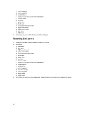
... d) system-board shield e) input/output (I/O) board shield f) WLAN card g) optical drive h) hard drive i) intrusion switch j) power and on -screen display (OSD) buttons board j) intrusion switch k) hard drive l) optical drive m) WLAN card n) input/output (I/O) board shield o) system-board shield p) VESA mount bracket q)... secure the camera to the chassis. 40 f) power supply unit g) power-supply fan h) converter board i) power and on -screen display (OSD) buttons board k) converter board l) processor fan m) power supply unit n) heat-sink assembly o) power-supply fan p) system board q) display...
... d) system-board shield e) input/output (I/O) board shield f) WLAN card g) optical drive h) hard drive i) intrusion switch j) power and on -screen display (OSD) buttons board j) intrusion switch k) hard drive l) optical drive m) WLAN card n) input/output (I/O) board shield o) system-board shield p) VESA mount bracket q)... secure the camera to the chassis. 40 f) power supply unit g) power-supply fan h) converter board i) power and on -screen display (OSD) buttons board k) converter board l) processor fan m) power supply unit n) heat-sink assembly o) power-supply fan p) system board q) display...

Owner's Manual
Page 41
Install: a) display panel b) system board c) power-supply fan d) heat-sink assembly e) power supply unit f) processor fan g) converter board h) power and on-screen display (OSD) buttons board i) intrusion switch j) hard drive k) optical drive l) WLAN card m) input/output (I/O) board shield n) system-board shield o) VESA mount bracket p) back cover q) VESA stand 4. Connect the camera cable and fix the latch. 3. Follow the procedures in After Working Inside Your Computer. 41 Installing the Camera 1. Tighten the screws to secure the camera to the chassis. 2.
Install: a) display panel b) system board c) power-supply fan d) heat-sink assembly e) power supply unit f) processor fan g) converter board h) power and on-screen display (OSD) buttons board i) intrusion switch j) hard drive k) optical drive l) WLAN card m) input/output (I/O) board shield n) system-board shield o) VESA mount bracket p) back cover q) VESA stand 4. Connect the camera cable and fix the latch. 3. Follow the procedures in After Working Inside Your Computer. 41 Installing the Camera 1. Tighten the screws to secure the camera to the chassis. 2.

Setup And Features Information Tech Sheet
Page 2
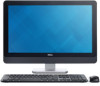
microphone (right) NOTE: The location of microphone varies in the non-touch version. 6. stand Figure 2. memory card reader 2 5. optical drive (optional) Back View 8. On-Screen Display (OSD) buttons (3) 10. VESA cover 4. microphone connector 7. 4. back panel connectors 2. headphone connector display 7. security cable slot 3. camera LED 5. Back View 1. power button 12. USB 3.0 connectors (2) 6. optical drive eject button 9. hard-drive activity light 11.
microphone (right) NOTE: The location of microphone varies in the non-touch version. 6. stand Figure 2. memory card reader 2 5. optical drive (optional) Back View 8. On-Screen Display (OSD) buttons (3) 10. VESA cover 4. microphone connector 7. 4. back panel connectors 2. headphone connector display 7. security cable slot 3. camera LED 5. Back View 1. power button 12. USB 3.0 connectors (2) 6. optical drive eject button 9. hard-drive activity light 11.